The GOALS Approach: Business and Software Modeling
Traceability by means of Human-Computer Interaction
Enterprise Modeling Language and Method
PhD Thesis
Pedro Valente
Supervisors
Nuno Nunes
Marco Winckler
Acknowledgements
I wish to thank my Professor Nuno Nunes, who believed in me from the beginning of the project, and to Professor Marco Winckler who further supported me in believing in myself.
I wish to thank the UMa Rector, Professor José Carmo and his Rectory, who gave me personal support to go to France in order to work in my thesis, as requested by me and my supervisors.
I wish to thank my Mother and Father, who gave all the support that I needed when I needed.
Abstract
The management of an enterprise relies on the continuous organization and development of its business and software systems. A process that requires merging the ideas of the enterprise’ systems managers, targeting the specification of business requirements and the conception and implementation of a supporting information system. This process finds obstacles in the identification and communication of requirements, and also in their transformation in software artefacts, leading to difficulties or loss of traceability between business and software models. Existing methods, languages and techniques are still not sufficiently standardized to ensure that when a business improvement is introduced, the supportive software solution will be implemented within budget and time. Methods are still too closed to the concepts of their original scientific domains, conceiving solutions which are not representative of the business and software conceptual relation and of the complexity concealed in an improvement effort, namely concerning usability and user experience. Moreover, the lack of a common modeling language and method for the conception of holistic and traceable software solutions, also refrains the performance of the enterprise development process. The GOALS Approach presents a solution to surpass these barriers by means of the specification of an enterprise modeling language that relates the business and software conceptual structures using a shared set of concepts, a notation, process, method and techniques, that allow the design of the software as a result of the business organization, ensuring traceability by means of the permanent representation of the business structure in the software structure.
Contents
1. Introduction ... 1
1.1. Origins ... 3
1.2. Motivation ... 4
1.2.1. Business Modeling Contribution ... 5
1.2.2. Software Modeling Contribution ... 6
1.3. Research Question ... 6
1.4. Thesis Organization ... 10
2. State of The Art ... 11
2.1. The Zachman Framework for Enterprise Architecture ... 12
2.2. Business-driven Modeling Methods ... 13
2.2.1. Service Design ... 13
2.2.2. Enterprise Engineering ... 14
2.2.3. Business Process Management ... 17
2.3. Human-centric based Methods ... 18
2.3.1. Human-Computer Interaction ... 18
2.4. Software-oriented Modeling Methods ... 19
2.4.1. Requirements Engineering ... 20
2.4.2. Software Engineering ... 22
2.4.3. Service Oriented Architecture ... 25
2.5. Matching of the Goals Approach ... 26
2.6. Traceability ... 27
2.7. Conclusions ... 28
3. The Goals Language ... 30
3.1. Structure... 30
3.1.1. Semantics ... 32
3.2. Enterprise Structure Concepts ... 33
3.2.1. Business Process (BP) ... 33
3.2.2. User Task (UT) ... 34
3.2.3. Interaction Space (IX) ... 36
3.2.4. Business Rule (BR) ... 38
3.2.5. Data Entity (DE) ... 39
3.3. Software Architecture Concepts ... 40
3.3.1. Aggregation Space (AS) ... 41
3.3.2. Interaction Component (IC) ... 42
3.3.3. Interaction Object (IO) ... 43
3.3.4. User Interface System Responsibility (UISR) ... 44
3.3.5. Database System Responsibility (DBSR) ... 45
3.4. Conclusions ... 47
4. The Goals Process, Method and Techniques ... 48
4.1.1. Iterative and Incremental ... 49
4.1.2. Strategy ... 50
4.2. Method ... 50
4.2.1. Architectural Control and Agility ... 52
4.2.2. Architectural Interaction Patterns ... 53
4.3. Case Study – “iKiosk” Project ... 54
4.3.1. Analysis Phase ... 55
4.3.1.1. Step 1 - Service Design ... 55
4.3.1.2. Step 2 - Business Process Design ... 57
4.3.1.3. Step 3 - Enterprise Structuring ... 58
4.3.1.4. Step 4 - Task Modeling ... 60
4.3.2. Design Phase ... 62
4.3.2.1. Step 5 – User Interface Design ... 62
4.3.2.2. Step 6 – Business Logic Structuring ... 67
4.3.2.3. Step 7 – Database Structuring ... 68
4.3.2.4. Step 8 – Software Architecting ... 69
4.3.3. Case Study Conclusions ... 70
4.4. Case Study - “Star Project” ... 71
4.4.1. Step 1 - Service Design ... 72
4.4.2. Step 2 - Business Process Design ... 74
4.4.3. Step 3 - Enterprise Structuring ... 75
4.4.4. Step 4 - Task Modeling ... 76
4.4.5. Step 5 – User Interface Design ... 77
4.4.6. Step 6 – Business Logic Structuring ... 80
4.4.7. Step 7 – Database Structuring ... 81
4.4.8. Step 8 – Software Architecting ... 82
4.4.9. Case Study Conclusions ... 83
4.5. Conclusions ... 84
5. Goals EA Template ... 85
5.1. Organization ... 85
5.1.1. Stereotype Organization ... 86
5.2. Diagrams ... 87
5.3. Architectural Views ... 89
5.4. Conclusions ... 90
6. Validation ... 91
6.1. Cross-Consistency ... 91
6.2. Power of Expression ... 95
6.2.1. Service Design ... 95
MORELLI & TOLLESTRUP ... 95
SERVICE EXPERIENCE BLUEPRINT (SEB) ... 96
6.2.2. Enterprise Engineering ... 96
DEMO ... 96
BUSINESS MOTIVATION MODEL ... 99
ARMOR ... 99
6.2.3. Business Process Management ... 100
BUSINESS PROCESS MODEL AND NOTATION (BPMN) ... 100
KLUZA & NALEPA ... 101
PUTZ & SINZ ... 101
6.2.4. Human-Computer Interaction ... 101
CEDAR ... 102
SOUSA ... 102
NAVARRE ... 103
6.2.5. Requirements Engineering ... 103
GONZÁLEZ & DÍAZ ... 103
KORHERR & LIST ... 104
KAOS ... 105
I-STAR (i*) ... 105
MÁZON ... 106
6.2.6. Software Engineering ... 106
RATIONAL UNIFIED PROCESS (RUP) ... 107
PHILLIPS & KEMP... 109
DENNIS ... 110
GRAHAM ... 111
6.2.7. Service Oriented Architecture ... 111
ARSANJANI ... 111
6.3. Validation Conclusions... 112
7. Conclusions ... 114
7.1. Future Work ... 116
7.1.1. Platform Specific Model for Information System Generation ... 116
7.1.2. Software Product Lines ... 116
7.1.3. Software Effort Estimation ... 116
7.1.4. Goals Modeling Tool ... 116
References ... 117
Appendix A – The Goals Conceptual Approach ... 124
Appendix B – Interaction Patterns ... 126
Appendix C – “iKiosk” Project Diagrams ... 128
Appendix D – “Star Project” Diagrams ... 131
List of Figures
Figure 1. GOALS Origins. ... 3Figure 2. ZF Matching of the SD methods. ... 14
Figure 3. ZF Matching of the EE methods. ... 16
Figure 4. ZF Matching of the BPM methods. ... 18
Figure 5. ZF matching of HCI methods. ... 19
Figure 7. ZF Matching of the RE methods. ... 21
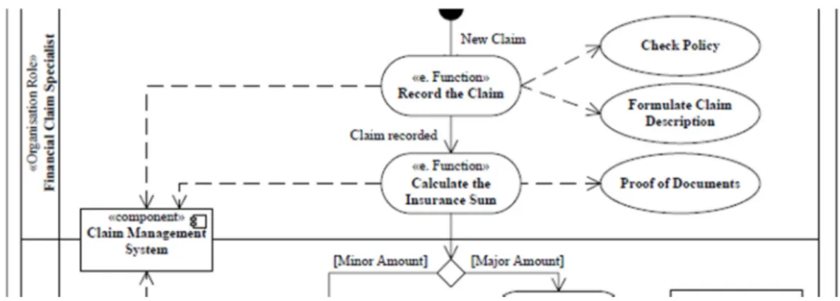
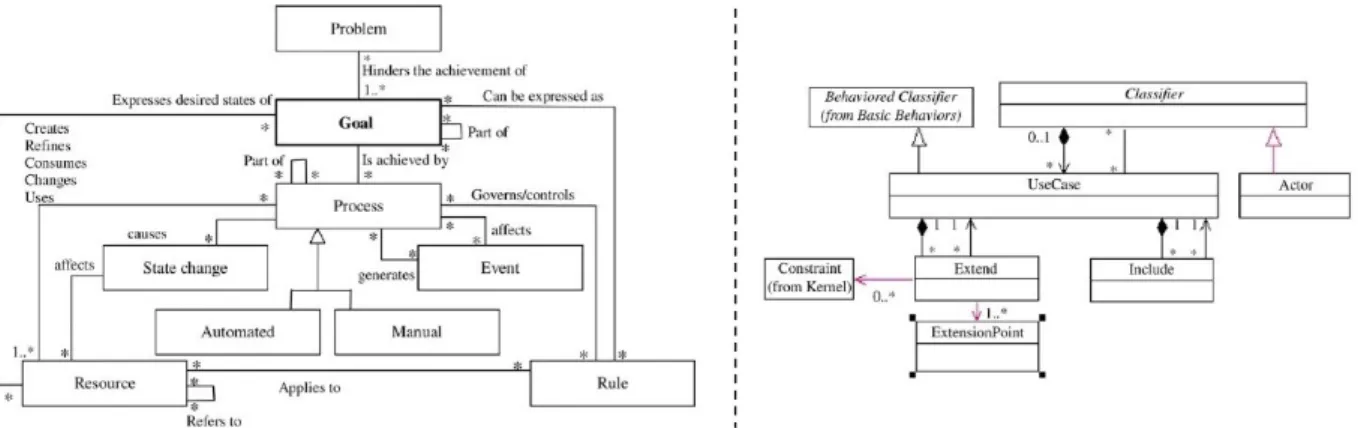
Figure 8. FDAF Meta-Model of Business Process and Use Cases. ... 23
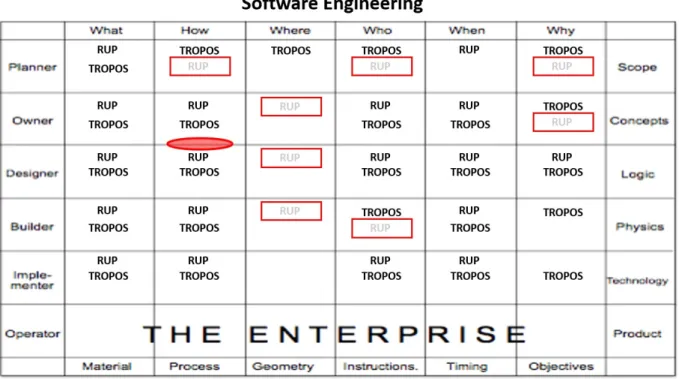
Figure 9. ZF Matching of the SE methods RUP and TROPOS. ... 24
Figure 10. ZF Matching of SOA methods. ... 25
Figure 11. ZF Matching of GOALS. ... 26
Figure 12. CVM Traceability Problem Specification. ... 27
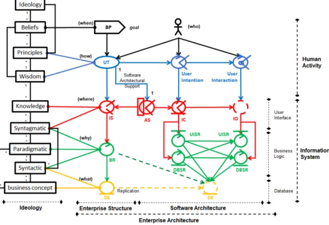
Figure 13. The GOALS Language Structure. ... 32
Figure 14. Meta-Model and Example of Business Process (BP). ... 34
Figure 15. Meta-Model and Example of User Task (UT). ... 35
Figure 16. Meta-Model and Derivation of IXs from UTs and relation to BRs and DEs. ... 37
Figure 17. Meta-Model and Example of Business Rule (BR). ... 38
Figure 18. Meta-Model and Example of Data Entity (DE). ... 40
Figure 19. Meta-Model and Example of Aggregation Space (AS). ... 41
Figure 20. Meta-Model and Example of Interaction Component (IC). ... 42
Figure 21. Meta-Model and Example of Interaction Object (IO). ... 43
Figure 22. Meta-Model and Example of User Interface System Responsibility (UISR). ... 45
Figure 23. Meta-Model and Example of Database System Responsibility (DBSR). ... 46
Figure 24. GOALS Process Analysis and Design Phases Modeling Concepts. ... 49
Figure 25. Goals Enterprise Development Process (EDP) Iterative Process. ... 49
Figure 26. GOALS Method Steps (1 to 8) and suggested Techniques. ... 51
Figure 27. “Simple - Interaction Design” Pattern. ... 53
Figure 28. Step 1 - Service Design Meta-Model and Example (“iKiosk” Project). ... 56
Figure 29. Step 2 – BP Design Meta-Model | Example of “Publish Classified” BP. ... 57
Figure 30. Enterprise Structure IX Diagram for “Publish Classified” BP. ... 59
Figure 31. Step 3 - Enterprise Structure Meta-Model | Example of “Publish Classified” BP. 60 Figure 32. Step 4 - Task Modeling Meta-Model and Example for “Insert Classified” UT. .... 61
Figure 33. Canonical Abstract Prototypes (CAPs). ... 63
Figure 34. Step 5 - Interaction Model Meta-Model | “Insert Classified (Text/Image/Link)”. . 64
Figure 35. Step 5 - User Interface Design of “Insert Classified” AS. ... 64
Figure 36. Example of User Interface Components Reuse. ... 65
Figure 37. User Interface Design for the Front-End of the “iKiosk” website. ... 66
Figure 38. Step 6 - Business Logic Structuring Meta-Model and Example. ... 67
Figure 39. Step 7 - Database Structuring Meta-Model and Example. ... 68
Figure 40. Step 8 - Software Architecture Example. ... 69
Figure 41. Step 1 - Service Design (“Star Project”). ... 73
Figure 42. Step 2 – Business Process Design of “Grow Community Project”. ... 74
Figure 43. Enterprise Structure Interaction Spaces Diagram. ... 75
Figure 44. Step 3 – Enterprise Structure of “Grow Community Project” BP. ... 76
Figure 45. Step 4 – Task Model | “Attract … Community”/“Support Project”. ... 77
Figure 46. Step 5 – Interaction Model | “Analyze … Intervention Information”. ... 78
Figure 47. User Interface Example. ... 79
Figure 48. User Interface Reuse Example. ... 79
Figure 49. Step 5 – Website Design of the “Star Project”. ... 80
Figure 50. Step 6 – Business Logic Structuring | “… Intervention Possibility”. ... 81
Figure 51. Step 7 – Database Structuring. ... 81
Figure 52. Step 8 – Software Architecture. ... 82
Figure 54. EA - Stereotypes Organization Tool. ... 86
Figure 55. EA - Package and Diagram Creation. ... 87
Figure 56. EA - Diagram Creation. ... 87
Figure 57. EA - Class Edition and Duplication (only changes the name) Tools. ... 88
Figure 58. EA - Relations between Classes. ... 88
Figure 59. EA - Setting the Visibility of Relations. ... 89
Figure 60. Enterprise Structure as an example of Enhanced Architectural View. ... 89
Figure 61. Cross-Consistency Matric of the GOALS Concepts. ... 92
Figure 62. Cross-Consistency Matrix and the GOALS Method Steps. ... 93
Figure 63. MORELLI & TOLLESTRUP and GOALS Service Design Representation. ... 95
Figure 64. SEB and GOALS Comparison. ... 96
Figure 65. DEMO and GOALS Relation of Concepts. ... 97
Figure 66. GOALS Representation of Transactions including More Than One Actor. ... 98
Figure 67. ARCHIMATE Modeling of the GOALS Structure. ... 98
Figure 68. BMM Model using the GOALS Language... 99
Figure 69. ARMOR Structure and Representation using the GOALS Language. ... 100
Figure 70. BPMN and GOALS equivalent BP Design. ... 100
Figure 71. KLUZA & NALEPA and GOALS equivalent Requirements Elicitation. ... 101
Figure 72. PUTZ & SINZ and GOALS equivalent Representation. ... 101
Figure 73. CEDAR and GOALS HCI Representation and User Interface Architecture. ... 102
Figure 74. SOUSA and GOALS User Interface Architectural Similarities. ... 102
Figure 75. NAVARRE and GOALS User Interface Architecture Representation. ... 103
Figure 76. GONZÁLEZ & DÍAZ and GOALS Requirements Elicitation. ... 104
Figure 77. KORHERR & LIST and GOALS Requirements Elicitation Representation. ... 104
Figure 78. KAOS and GOALS Concept Mapping and Example. ... 105
Figure 79. I* and GOALS equivalent Representation. ... 105
Figure 80. MAZÓN and GOALS equivalent Representation. ... 106
Figure 81. GOALS Change relatively to the RUP SDP. ... 107
Figure 82. RUP and GOALS Architectural Organization. ... 108
Figure 83. RUP PHILLIPS & KEMP and GOALS User Interface Architecture. ... 110
Figure 84. DENNIS and GOALS Relation of Use Case Concepts. ... 110
Figure 85. GRAHAM and GOALS Similarities to I*. ... 111
Figure 86. ARSANJANI and GOALS SOA Representation. ... 112
Figure 87. GOALS and Related Work Concepts Comparison. ... 113
Figure 88. Design Patterns for Human-Computer Interaction. ... 126
Figure 89. Design Pattern: Service Oriented Architecture (SOA). ... 127
Figure 90. Business Process “Decoy”. ... 128
Figure 91. Business Process “Publish Advertisement”. ... 128
Figure 92. Business Process “Validate Reporter”. ... 128
Figure 93. Enterprise Structure “Decoy”. ... 129
Figure 94. Enterprise Structure “Publish Advertisement”. ... 129
Figure 95. Enterprise Structure “Validate Reporter” ... 129
Figure 96. Task Model “Deliver Printing”, “Receive Payment”, “Serve Coffee” UT. ... 130
Figure 97. Task M. “Support Customer Activity”,“Obtain Classified”,“Obtain News” UT. 130 Figure 98. Task Model “Publish Reporter News” ... 130
Figure 101. Business Process “Support Investment”. ... 131
Figure 102. Enterprise Structure “Conceive Investment Project”. ... 132
Figure 103. Enterprise Structure “Evaluate Investment”. ... 132
Figure 104. Enterprise Structure “Support Project”. ... 132
Figure 105. TM “Present Investment Possibilities”|“Investment Possibilities Feedback”. ... 133
Figure 106. TM “Present Project” | “Support Project”. ... 133
List of Tables
Table 1. The Zachman Framework (ZF) Matrix. ... 12Table 2. Results of the ZF Matching. ... 28
Table 3. Enterprise Structure Concepts Definition, Origin and Symbol. ... 30
Table 4. Interaction Design Concepts Definition, Origin and Symbol. ... 31
Table 5. Software Architecture Specific Components, Definition, Origin and Symbol. ... 31
Table 6. GOALS Method Steps, Input and Outputs, and Affinity of Responsibility. ... 52
Table 7. BDD Pseudo-Code and GOALS Components Relation. ... 63
Table 8. “iKiosk” Project Development Process. ... 70
Table 9. “Star Project” Development Process. ... 83
List of Acronyms
AS – Aggregation Space BP – Business ProcessBPI – Business Process Improvement BR – Business Rule
DBSR – Database System Responsibility DE – Data Entity
EDP – Enterprise Development Process IC – Interaction Component
IO – Interaction Object IX – Interaction Space
ROI – Return of the Investment SDP – Software Development Process UISR – User Interface System Responsibility UT – User Task
UX – User Experience ZF – Zachman Framework
Formatting
concept - italic – business and/or software modeling concept.
Model - capitalized - business and/or software model.
Technique - italic capitalized - business and/or software modeling technique.
METHOD – all capitalized - business and/or software modeling method or language.
1.
Introduction
Traceability of business and software modeling is a requisite concerning business and Information Technology (IT) alignment, and may be perceived as the cornerstone of enterprise development performance. Traceability is the establishment of a relation between business and software concepts that allows the recognition of which components of the business are supported by which components of the Information System, and what may be the impact of changing business requirements over the software structure. Complementarily, by means of
traceability, it is possible to acknowledge which aspects of the business are still not supported by a software system (and which are), so that new improvements may be identified. These improvements may be introduced at an acceptable rate, especially if the translation of business and software models is avoided [de Vries et al., 2017; Ouyang et al., 2009]. The translation process overhead is in fact what justifies the introduction of a common language of shared concepts that may be used by business and software modelers to carry on the daily Enterprise Development Process (EDP), the process that coordinates the business and software modeling and implementation tasks.
The introduction of a new language in this context requires that the coordination of the ideas of business and software modelers concerning the enterprise are concealed, which may not be straightforward, as the perspectives of both, observing the same enterprise problem, are distinct. For business modelers, the problem is mostly related to the enactment and enhancement of
business processes, or Business Process Improvements (BPI), where people and software
represent solutions; whereas, for software modelers, those solutions are their analysis, design and implementation problem. To surpass this barrier, the concepts used in the dialogue must be properly understood, given the complexity and accuracy needed in the process of conceiving the enterprise solution. Nevertheless, the establishment of this language is possible, since on one hand, the business concepts with a bigger impact on software development may be recognized by software modelers (e.g. the business process, actor and regulation concepts),
and on the other hand, business modelers have general knowledge over the more fundamental software concepts (e.g. User Interface, programmed code and Database), as basic premises of a business and software modeling language. Therefore, if the language is close to this high-level of abstraction, the communication may be viable (effective) and fluent (efficient), instead of being an important obstacle [Ferreira & Wazlawick, 2011].
This thesis describes “The Goals Approach”, which aims at serving as a common language to support EDP. By conveying the perspectives which are usually involved in in-house software development and business management, we elaborated a method called “The Goals Approach”, originated from the “Goals Software Construction Process” [Valente, 2009], where “Goals”, an acronym, was ideated as “Goal-Oriented Approach (Led) Software”, expressing the target of letting the software development being “led” by the goals of the business processes, now
abbreviated to Goals Approach, and referred as “GOALS” throughout the thesis. Our work focuses in-house software development, for the reason that many enterprises should be aware that they can develop their own software, and because it is where it is originated from.
GOALS is based on a single language, modeling: the customer service and business processes
of the enterprise; and: the User Interface, the Business Logic, and the Database of the Information System, given a Model-View-Controller (MVC) pattern [Zukowski, 2013]. It produces a software architecture that includes the business architecture as its “back-bone”, ensuring traceability of business and software. By providing: a single structure based on a single architectural language; and the application of each technique; in a single method, we believe that we are creating conditions to enable the fluent dialogue of the (usually) multi-disciplinary teams that carry on the daily enterprise development practice (or EDP).
Our method provides support for the following development roles of practitioners:
• Business Owner, by providing a holistic view of the business and software, and an EDP that guides the modeling of both structures using a single method and language;
• Service Designer, by providing a tool to elaborate the customer interaction with the business, identify applicable regulations, the used and produced resources and systems;
• Business Process Manager, by proving a tool to design business processes with enhanced detail concerning their tasks, the used spaces, the regulations and data, using
modeling concepts which are understood in the software domain.
And complementarily, by providing a tool for software modelers, namely:
• Software Architect, by providing a holistic view of the Information System context, a process, a method, techniques and a modeling language that facilitates the elaboration of the conceptual architecture of the Information System;
• User Interface Designer, by supplying a structured business model, that includes the service design, regulations and resources, providing a user task context, to which are
applied user-centered techniques targeting performance and testing;
• Software Developer, by providing a Software Architecture that allows understanding the dependencies and importance of each programmed class by relating each component with the business model artefacts.
The Goals Approach is presented using capital letters (GOALS), a situation also be applied to other method’s names in order to facilitate recognition among Models and GOALS Modeling Concepts (both capitalized), Techniques (italic capitalized) and business and software
development usual concepts (italic not capitalized) names. We present GOALS as a solution to
1.1.
Origins
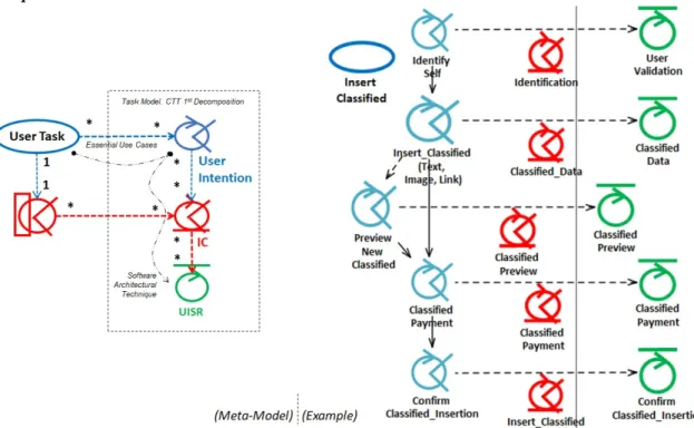
The combination of views and models is one of the originalities of the GOALS Approach. The approach relies on existing business and software languages to describe its underlying concepts. Our approach is mainly based on WISDOM [Nunes, 2001] which supplies the core software engineering process and the User Interface design focus [Nunes & Cunha, 2001], and on PROCESS USE CASES [Valente & Sampaio, 2007] (which is also a WISDOM extension), that establishes a structural relation between the business and software models using essential use cases [Constantine & Lockwood, 2001]. The GOALS Approach applies CTT (Concur-Task
Trees) [Paternò, 1999] in two-steps: (1st step) decomposing essential use cases in terms of User
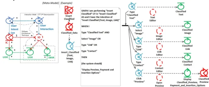
Intentions using a Task Model; and (2nd step) decomposing User Intentions in User Interactions
applying the BEHAVIOR DRIVEN DEVELOPMENT (BDD) [Chelimsky et al., 2010]) method, describing the system behavior, and designing the User Interface using modeling tools of the ACTIVITY MODELING (AM) method [Constantine, 2006]. The structuring of the system behavior and the internal structure of the Software Architecture comes from the WISDOM Software Architectural Technique, that provides support for the User Interface and
complements the Domain Model [Booch et al., 2005], for the specification of the Information System. GOALS is structured on DEMO [Dietz, 2006] as a mean to specify how business processes human interaction is supported by GOALS User Tasks (essential use cases),
including DEMO Action Rules and Object Classes, which are complemented with the Interaction Space (IX) concept, in order to support human interaction representation beyond the standard in-person interaction, and for more than two actors.
Figure 1. GOALS Origins.
1.2.
Motivation
The main motivation for the establishment of a single language is the improvement of the Software Development Process (SDP) performance. A unified business and software modeling language and method opens a space of communication for those who carry on the practice of modeling the business and the software. We formalize that a software development team includes the Software Architect, the User Interface Designer and the Software Developer
stakeholders. They have the responsibility of deciding the process, method, techniques and implementation models of the Information System. The project team is only complete with the stakeholders which are responsible for the business, which are the Business Owner, the Service Designer, and the Business Process Manager, whom have the responsibility of providing the resources, specifying (by modeling) and implementing (based on software or not) the business processes of the enterprise. We assume that any of the team members may accumulate more
than one role, and that a role may be composed by more than one member (a team) with distinct backgrounds. The objective is that all may use the same models and language so that they may understand the BPI and its impact in the customer and collaborator relation, and complementarily the impact of the improvement over the structure of the Information System.
By means of applying common development techniques, the business and software modelers may understand the implications of their decisions in the other modeler’s work. And by using the same method, they can also understand the logic that leads from one model to the other, and from one concept to the other, even if they are working at the top-level concept (the goal of the business process) or the detailed User Interface component that allows its faster execution. By
using the same language (and notation), project meetings may be faster, and by using the same models, the documentation may be reduced and will also be more easily recognizable, since it will be recurrently reused for the purpose of the ongoing “project dialogue”. As such, the produced models also have value for more stakeholders. By using recurrently the (same) notation, the semiology of the development practice may also benefit from the stability provided by the usage of common business and software symbols, and therefore may more easily be assimilated by the patterned enterprise development practices which may already exist. Beyond the objective of organizing and facilitating the process of transferring business requirements
and transforming them in a software architecture, also exists the objective of being able to understand how much working-time an Information System will take to be finished. Those metrics depend directly on the design of the business and the software parts which will be implemented. Yet, its measurement and therefore its estimation, can only be attained if the SDP is properly stabilized concerning the production of software as a business-support for the enterprise, probably optimized by means of the usage of a single enterprise modeling language.
1.2.1.
Business Modeling Contribution
One of the key factors for project success is reaching team consensus over the BPI concerns, which is easier if the team understands the relation of each of the business with each of the software modeling concepts, in order to promote a faster and more effective understanding. By using concepts which are originated from the scientific domains usually involved in in-house software development, with adaptations in terms of: scope, structure and relation (between concepts); our language introduces fruitful changes to the software development practice. The first change, of structure, is that business processes should be named after their goal, as it is the
enterprise-recognizable business concept that reflects the undergoing objective, helping
focusing the target of software implementation. The second change, of scope, concerns modeling the activities of the business processes using essential use cases [Constantine &
Lockwood, 2001], which are defined as “a complete task performed by one actor”, in order to
withdraw margins of uncertainty concerning requirements elicitation, especially in terms of
number, establishing a simplified and comprehensive (an “actortask-sized”) relation between
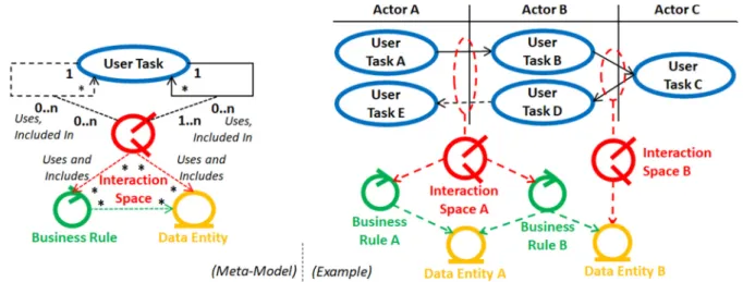
business and software models. The third change, of relation of concepts, is the inclusion of the Interaction Space (IX) as the space where communication between actors happens, and where
specific regulations are applied over the management of certain data. The relation between goals, essential use cases, IXs, regulations and data, is the “key” that enables the composition
of a business model that allows rationalization about the enterprise development problem on a single diagram, and serves as the “door” to the specification of the Information System which will support the BPI, as those concepts will be detailed, complemented and included as a part of the final Software Architecture. By means of using the same language in a single top-down analysis logic (from business process to data set), we are also creating conditions to focus on
what are the more important concepts that must be transferred from the business team to the software development team. As a result, less work may be lost in the transfer, and there is no need for translation efforts, contributing to increase the performance of the EDP.
The main contribution for the business modeling is related to the specification of a Business Architecture that can receive software architectural support independently of the type of design of its business processes. The Business Architecture (represented by the Enterprise Structure
model), becomes part of the Software Architecture, composing the Enterprise Architecture. The Enterprise Structure includes the Interaction Space (IX) as the “aggregator” of data and regulations which are at the disposal of the tasks which may be performed in those logical
spaces. The IX allows the representation of the interaction of one, two or more actors, and the
representation of the physical space where they interact, and which actions are performed. The IX is then included in the Software Architecture as the component that ensures the application of the business regulations (Business Rules, BR) and the usage of the data (Data Entities, DE).
The IXs, BRs and DEs are therefore shared concepts of the Business and Software Architectures, which also represent a contribution to the SE domain by means of the inclusion of the BR concepts as the business-specific concept of the Business Logic layer of the MVC pattern of the Information System.
Although the proposed modeling structure may be complemented in order to measure business process performance, using e.g. Key Performance Indicators (KPIs), these aspects are out of
1.2.2.
Software Modeling Contribution
The SDP performance can be strongly increased if the business model of the enterprise is structured on components which are meaningful to software practitioners, and which may be further detailed in order to produce the Information System internal structure. This is possible by means of the detail of the human activity “down” to the level of interaction, and may be achieved by using Human-Computer Interaction (HCI) techniques, representing an added value for both business and software modelers, as they will be able to identify the Information System components that support the business process-driven human mental and physical (partial,
working) activity. Once this is achieved, the dialogue between business and software modelers, including User Interface Designers, may be fluent and potentially more fruitful based on a
better understanding about the business-problem and software-solution under analysis, prospecting a project team faster agreement concerning the operationalization of the BPI. By integrating the Enterprise Structure (Business Architecture) as the conceptual “back-bone” structure of the Software Architecture, the received components (instantiations of concepts), only have to be complemented with software-specific components to be conceived as the final Information System implementation-independent architecture (the Software Architecture). As the produced structure is directly related to an MVC implementation model, a standardized straight-lined process may be assembled, based on a methodical implementation process easier to carry out, eventually with a closer support from business modelers.
As our focus is the organization and coordination of business and software modeling, the measurement of the development performance is out of the scope of the current version of our approach, as the organization and automation of the SDP can be seen as a pre-requisite of software success, aiming in the first place the effectiveness of the process, and in second place its efficiency.
1.3.
Research Question
The research question of our thesis concerns the establishment of a language and method to produce the artefacts which are needed for in-house software development. The question is considered as holistic in the perspective that, with a single language, one must be able to develop software solutions to all the business activities that manage enterprise data. The
pertinence of the question exists because actual software development methods do not cover all the business and software modeling relevant aspects maintaining traceability, and because the ones that do are not supported by a development method. The research question is formulated as follows.
Q1: Is it possible to establish a modeling language that can be applied by a single method which is representative of the organized business activity and its supportive software system?
The research method is originated from a logic that results from software development practice with academic support as needed. This first application resulted in the elaboration of the Software Architecture for a “major” BPI in the University of Madeira that included 5 “core”
business processes (from the pedagogical service: “distribution”, “scheduling”, “preparation”,
“lecturing” and “evaluation”). The Software Architecture was produced using WISDOM, and related to the enterprise business processes by means of PROCESS USE CASES, and its User
Interface was designed using CANONICAL ABSTRACT PROTOTYPES [Constantine et al., 2003], which received support from the HYDRA framework [Costa et al., 2007], for the implementation of the User Interface using the remaining identified (Business Logic and Database) Software Architecture components. The application was replicated for the implementation of 7 business processes (course “course inquiry”, “business unit management”,
“facilities management”, “facilities access control”, “academic billing system”, “student credits accreditation”, and “student academic background”), and leaded to the establishment of GOALS as an internal SDP standard. The method was further used for 3 more BPIs (“course accreditation”, “student’s academic requests” and “voting system”), before it was formalized starting in 2012, and continued to be applied as a form of validation of its models in other BPIs. Since traceability was found to be an unsolved problem in both Enterprise Engineering (EE) and SE domains, the method was formalized concerning the methodical application of its development techniques in consecutive steps.
As our research question targets business and software Information Systems modeling traceability, our hypothesis reflects the establishment of a language of shared concepts as a solution, as follows.
H1: It is possible by means of a cross-consistent relation of business and software concepts, and by modeling the business human activity and relating it to software-specific components of the software model by means of the application of architectural patterns.
The strategy that sustains H1 is mainly based on the identification of the spaces where users carry on their tasks, aggregating in a logical relation: the tasks, the business regulations and the data that apply in each case. These spaces are called as Interaction Spaces (IX), and where
found, in our opinion, to be the missing part of the business representation of existing methods, and it is based on it that we apply the remaining techniques that bridge business and software modeling. With the purpose of supporting H1, and beyond the validation provided by its recurrently successful application, GOALS also received distinct forms of validation, concerning: (1st) its performance, (2nd) its business structure, and (3rd) its conceptual structure:
• First, a study of the application of the method was carried out for five BPIs [Alves et al., 2013], using the iUCP method [Nunes et al., 2011] for post-project estimation and comparison of software development effort, revealing a performance stability that allowed the identification of: requirements volatility, software framework (change), and project type ; as aspects that add more (negative or positive) impact to the development
• Secondly, it was also evaluated concerning its business conceptual structure, by means of the comparison with the DEMO [Dietz, 2006] business process equivalent
representation [Valente et al., 2016b], highlighting the inclusion of the IX as the solution to provide software architectural support for the (DEMO) business process
Transactions, modeled with essential use cases to represent human activity, and
including the IX as the element that provides support for that activity by ensuring
regulations and data conformance, for two of more actors performing their tasks
(essential use cases) in remote or in-person interaction.
• Thirdly, the GOALS language structure was validated concerning the cross-consistency of concepts [Valente et al., 2017] (in a 10 step method, now presented in 8 steps), and architectural restrictions concerning the organization of the business and software models. The validation (extended) is presented in Section 6.1. Cross-Consistency. The method was also published concerning its agile Human-Centered Software Engineering (HCSE) perspective [Valente et al., 2016a], as a trade-off between agility and traceability (architectural control) of business and software representations.
Based on the previously referenced work, the formalization of our method when through distinct phases, which are described as follows:
• Effort Estimation and SDP Productivity Evaluation. A study was carried out in order to evaluate the use case as a “measure of effort” concerning software productivity using
the GOALS method. With a sample of five (University of Madeira) projects, two projects from other enterprises were added, providing a (statistically workable) heterogeneous sample of seven. From the analysis of the factors that mostly affected each project (requirements volatility, software framework (change), and project type),
it was possible validate a new formula effort of the iUCP method, by giving those factors a (bigger) weight that would reflect their real impact. The study received the honor of “Best Full Paper Award” from the conference.
o (Full Paper) [Alves et al., 2013] Alves, R., Valente, P., Nunes, N. Improving
Software Effort Estimation with Human Centric Models - A comparison of UCP and iUCP accuracy. In: Proceedings of 5th ACM SIGCHI Symposium on EICS
'13, London, England. pp. 287-296. (2013)
• User Experience and Service Design. A study was carried out, directed to the HCI and SE industry practitioners (sample of 97 questionnaires), in order to understand how the User Experience (UX) concerns were considered within the software development practice. It allowed understanding how strongly BPI (“business reorganization”)
projects are related to the (paper) prototyping of the User Interface, namely in the phases of requirements elicitation, design and testing. And confirm that refactoring is strongly correlated to requirements evaluations (introduction or change).
o (Full Paper) [Alves et al., 2014] Alves, R., Valente, P., Nunes, N. The State of
User Experience Evaluation Practice. In: Proceedings of the 8th Nordic
Conference on Human-Computer Interaction, pp. 93-102. (2014)
o (Short Paper) [Valente et al., 2015] Valente, P., Aveiro, D., Nunes, N. Improving
Software Design decisions towards enhanced Return of Investment. In:
Proceedings of ICEIS 2015, Barcelona, Spain. pp. 388-394. (2015)
• Intention to Bridge EE and SE. The intention of bridging EE and SE was discussed as a project in a Doctoral Consortium, including the actual business model, the importance of defining an enterprise-sized development process (EDP) that includes the software development, and how effort estimation may be based on business and software models in the future (by weighting architectural components).
o (Doutoral Consortium) Valente, P., Aveiro, D., Nunes, N. (2015). Bridging EE
and SE: The Goals Approach. Enterprise Engineering Working Conference.
https://www.researchgate.net/publication/283289437_Bridging_EE_and_SE_T he_Goals_Approach
• Business Model based on DEMO. The GOALS business model and its relation with
the DEMO model was published, and how the “bridge” to Software Architecture could be achieved by means of a User-Centered perspective, applying the method with a total of 10 steps (now reduced to 8).
o (Short Paper) [Valente et al., 2016b] Valente, P., Silva, T, Winckler, M., Nunes, N. Bridging Enterprise and Software Engineering through a User-Centered Design perspective. In: Proceedings of the Web Information Systems
Engineering (WISE) 2016 Conference. (2016)
• GOALS and Systems Development. The GOALS method was published, targeting its
meta-model and concepts cross-consistency validation. Targeting model-driven in-house software development, focus is also made on the technology that may be applied to implement each Software Architecture component.
o (Full Paper) Valente, P., Silva, T, Winckler, M., Nunes, N. The Goals Approach:
Agile Enterprise Driven Software Development. In: Proceedings of the
Information System Development (ISD) 2016 Conference. (2016)
o (Extended Full Paper) [Valente et al., 2017] In: Lecture Notes in Information Systems and Organisation, 22. (2017)
• GOALS and Human-Centered Software Engineering. The GOALS method was
published focusing the proposal of a trade-off between business architectural control and agile (user) task-sized (User Task (UT)) improvement efforts, and the need to
induce the multi-disciplinary work within enterprises targeting project success.
o (Full Paper) [Valente et al., 2016a] Valente, P., Silva, T, Winckler, M., Nunes, N. The Goals Approach: Enterprise Model-driven Agile Human-Centered Software Engineering. In: Proceedings of the HCSE+HESSD 2016 Conference.
(2016)
1.4.
Thesis Organization
The thesis is organized in seven chapters, which we introduce as follows.
• Chapter 2. State of The Art, presents the state of the art concerning business and software modeling traceability, focusing on the business model conception, and how
requirements are elicited targeting the software model architecting;
• Chapter 3. The Goals Language, presents the structure of our language, its concepts, stereotypes and definitions, including their meta-model, an example, and their origin; • Chapter 4. The Goals Process, Method and Techniques, presents the process, method
and techniques, including two case studies based on a real software development projects: (“iKiosk”) focusing the method application, and; (“Star Project”), focusing the decisions taken during the application of the method.
• Chapter 5. Goals EA Template, presents how our method may be applied using a software tool available in the market (Enterprise Architect);
• Chapter 6. Validation, presents the validation of the language by means of its internal cross-consistency, and its power of expression by means of comparison with other methods;
2.
State of The Art
The scope of our language and method is the modeling of the business and the supporting Information System, targeting the specification of a business-traceable Software Architecture suitable for in-house software development. In this scope, we find the intention of “bridging” business and software models in methods originated from Enterprise Engineering (EE), based on business modeling, in Software Engineering (SE), targeting software modeling, and in Human-Computer Interaction (HCI), targeting software system behavior modeling for the support of human activity. These domains specify the requirements of an enterprise Information
System that contains data, implements business regulations, and provides adequate behavior
i.e. an Information System suitable for the daily enterprise operation. EE, SE and HCI, are in the origin of our proposal, and are complemented with the Service Design (SD), Business Process Management (BPM), Requirements Engineering (RE) and Service Oriented Architecture (SOA) domains, to extend these requirements to consider enhanced service and
business process experience and connectivity. Each domain is introduced as follows.
In the business perspective, the SD domain represents a very wide scope in terms of Information Systems requirements, which refers not only to the usability of the software, but also to the
(emotional) User Experience (UX) in interaction with the business [Alves et al., 2014]. EE methods model the enterprise by means of elaborating Enterprise Architectures that include
actors and business processes, and also transactions, regulations and data structures. The
structures may be complemented with Organizational Operative Systems (OOS) to generate operational software, and with software development methods concerning Information System engineering. Closer to the SE domain, in the field of automatic code generation, BPM methods produce Workflow Management Systems (WfMS) from business process models, usually
integrating business regulations in the final Software Architecture, which has a parallelism with
the EE approaches that produce working software.
In a human-centric perspective, HCI methods are not holistic business representations, however, they consider the context of interaction and also what the user expects from the system, usually with structured feedback, promoting the user performance and UX, besides and beyond ensuring usability. Those methods also produce valid in-house software architectures in the cases when they also include business regulations, and produce Database valid
information by means of business concepts that model the domain of the Information System.
In an Information System engineering perspective, RE strongly addresses the problem of traceability, observing it as the consequence of eliciting requirements from business models,
independently of the used form (e.g. goal, use case, aspect or feature); techniques which are
crucial in terms of elicitation capability and accuracy, as requirements generate the complexity
managed in a SDP. In SE, existing methods elicit business requirements and apply
transformations that produce Software Architectures. These are Model-Driven Architecture (MDA) methods, which are mostly derived from the RATIONAL UNIFIED PROCESS (RUP) [Kruchten, 2004], based on the responsibility which is isolated in use cases as a source of requirements. SOA methods, model the service and produce web-service structures that
The more representative methods of each domain will be analyzed concerning Information System conception and the requirements defined by the Zachman Framework [Zachman, 1986], with the purpose of understanding how comprehensive each method is, and how business and software traceability is achieved. We present the Zachman Framework as follows.
2.1.
The Zachman Framework for Enterprise Architecture
The Zachman Framework (ZF) [Zachman, 1986], was conceived with the purpose of understanding the scope of what must be controlled within an enterprise, so that all of its parts are documented to provide a holistic view of the enterprise architecture which may be used as a base of its management. The ZF scope of analysis of the enterprise includes its business and Information System, divided in levels, from the more abstract to the more concrete perspective: “Scope”, “Concept”, “Logic”, “Physics”, “Technology”, and “Product”, relative to the roles of “Planner”, “Owner”, “Designer”, “Builder”, “Implementer”, and “Operator”. These are crossed with the interrogatives: “What?”, “How?”, “Where?”, “Who?”, “When?”, and “Why?”; specifying the enterprise architecture independently of the used method and notation. The ZF provides an ontology about the object under study, which in our case is the modeling of the business and software systems of the enterprise, the initial purpose of the ZF, despite the fact that it may be used for every type of object (besides the enterprise: a project, an airplane, a building, etc.) [Zachman, 2008].
Table 1. The Zachman Framework (ZF) Matrix.
This logic allows the representation of the enterprise architecture, to which we introduce a change concerning the specification of the “Where” column and the concept of “Distribution”, by means of extending it to the logical location, adding it to the original proposal (which initial name is “Network”), which refers to physical location, allowing it to also support virtual enterprises. Thus, this column has enhanced meaning if both physical places and logical spaces of the enterprise system are also represented in the architecture, whereas, the data network,
should only be considered at the “Operation” level, which represents the materialization of the enterprise, and which is out of the scope of our analysis. The more representative methods of each scientific domain will be matched with the ZF, according to the literature review, which we present as follows.
2.2.
Business-driven Modeling Methods
Business models aim at structuring the business with humans and system as equivalent and complementary parts towards the operationalization of the enterprise strategy. In the business modeling perspective, the organization of the parts usually relies on advanced technology from which the Information System conception must be tailored in order to fit the enterprise performance needs. The Service Design (SD), Enterprise Engineering (EE), and Business Process Management (BPM) more representative methods are presented as follows.
2.2.1.
Service Design
Service Design (SD) started as a discipline of marketing and management of the service, where the specification of products and services assumed an important role in the modeling of the service and customer interaction, demanding levels of usability from Information Systems that may support its customer-oriented strategy. The EXPERIENCE CYCLE [Dubberly & Evenson, 2008] is a customer oriented method that defines a specific strategy for the service-customer relation, in which the objective is to “Orient” (the customer), “Interact” (with the customer), so that the customer will probably wish to “Extend & Retain” (the experience), “Advocate” (about it), and “Connect & Attract” (other customers). The BLUEPRINT [Shostak, 1982] was the pioneer method, relating services and products for the purpose of designing the service as a whole. The BLUEPRINT establishes a relation that can be used for different purposes, including the development of Service Oriented Architectures (SOA) [Becker et al., 2008] (SOA methods are analyzed in Section 2.4.3. Service Oriented Architecture). In the BLUEPRINT, the logic that relates processes and resources is the rationale behind the way of thinking, analyzing
and delineating the business. This logic by itself is however far from the level of detail needed to design the proper User Interface that satisfies customers over time. SD methods also express human intention and activity with detail.
The SERVICE EXPERIENCE BLUEPRINT (SEB) [Patrício et al., 2008], is a method based on the BLUEPRINT that decomposes softgoals and goals, and further specifies the relation
between the actions that the user takes in the dialogue with the enterprise system as his experience sequence (the route), in a similar way that essential use cases are decomposed in
terms of user intentions and system responsibilities [Constantine & Lockwood, 2001]. SEB prevents the over-decomposition of requirements (too much granularity) before task analysis
The SD challenges can also be considered as a reference concerning usability as they also design the user’s (customer) emotions. The MORELLI & TOLLESTRUP’s [Morelli & Tollestrup, 2006] method, elaborates a motivation matrix compliant with the user experience levels demanded by the market [Pine & Gilmore, 1998], that may eventually be used to design User Interfaces with a level of performance. This method is an example of a valid high-level requirements modeling approach targeting the specification of Information Systems, however, the modeling of the internal structure of the system, or even the User Interface, is out of the scope of the method beyond the proposed identification of use cases.
Figure 2. ZF Matching of the SD methods.
Figure 2 presents the matching of the SD methods concerning service elaboration, traceability and software development. It is possible to identify that the EXPERIENCE CYCLE and the BLUEPRINT methods cover the top of the conceptual logic of the ZF, providing insight of the logic of the business, the customer intention and the expected route of interaction. The Becker method focuses on functionality in a SD branch that directly relates to SOA, and the MORELLI & TOLLESTRUP’s method focus on motivation not however providing a software architecture. The SEB method relies on essential use cases decomposition based on a line of
interaction avoiding use cases indefiniteness in the representation of the customer relation.
2.2.2.
Enterprise Engineering
The Business Motivation Model (BMM) is an enterprise strategy model. BMM targets the specification of the reasons “why” the enterprise acts towards a given “objective”, and how it should achieve it. The model serves as a support in order to understand the existence of the
business processes of the enterprise, and what are the desired results, according to the enterprise
strategic vision. BMM reflects only a part of what is the business model, since business processes are not designed, as the concerns are more related to the courses of action as a whole,
and the related business rules and policies conception, including their relation to internal and external motivators. BMM does not consider the software model.
The Open Group Architecture Framework (TOGAF) [The Open Group, 2011], is a method that predicts the elaboration of a business, a data, a technology, and an application architecture.
TOGAF targets the specification of the enterprise, and the identification of its building blocks using the ARCHIMATE language [The Open Group, 2012]: “Application Component”, “Application Function”, “Application Interface”, “Application Service”, and “Data Object”. These architectural components may be related to equivalent business components, including “Business Services” and “Business Processes”, and also to infrastructure (e.g. software server) components. However, the identified building blocks do not provide enough detail in order to architect the software system, and as such, TOGAF does not establish a relation that ensures traceability at the level of the implemented component. Yet, as the application parts are identified along with the business processes, other SE methods may be used in order to model
the software, such as the ARMSTRONG method [Armstrong et al., 2013], published by The Open Group. The resulting transformation of the method uses the “Business Interaction” to derive “Business Use Cases” between the involved actors, and then use an Activity Diagram to
represent the business process of that interaction, with which it derives the functionality that
must be implemented by use cases. In our perspective, this method also leaves gaps in the
relation between the business and software modeling relation, namely: what is the relation between the “Business Use Cases” and the business process “activities”, and what is the relation
between the “activities” and the use cases, also skipping the design of the User Interface.
Moreover, TOGAF provides a set of modeling tools and documentation which we do not find as suitable for in-house software development, and observe it as a potential threat to the efficiency of the SDP due to management time overhead.
DEMO [Dietz, 2006] is an enterprise engineering method that produces valuable business and software artefacts concerning Information System conception. Software development is usually prospected using the GENERIC SOFTWARE DEVELOPMENT PROCESS (GSDP) [Kervel et al., 2013], which derives software specifications from the DEMO enterprise ontology to a system ontology. However, DEMO and the derived methods do not contemplate the User Interface design, since the user task model does not provide sufficient detail besides the
(“coordination”) acts (“request”, “promise”, “state” and “accept”), of a transaction between
two actors. Another approach to Information System conception is the software
operationalization by means of ORGANIZATIONAL OPERATING SYSTEMS (OOS) [Páscoa & Tribolet, 2015], which is also based on DEMO models, in order to deploy operational software. Yet, as DEMO does not produce enough information for User Interface specification besides the business process work flow and the coordination acts, the usability of the system
ARMOR [Engelsman & Wieringa, 2012] is a method that adapted concepts from other methods, namely TOGAF [The Open Group, 2011], KAOS [Lamsweerde, 2000], i* [Yu, 1995], TROPOS [Morandini et al., 2014] and BMM [Object Management Group, 2007] in order to establish the specification of an Enterprise Architecture. The ARMOR architecture specifies the business in terms of stakeholder’s goals, including the “influence” to which they are subject
to, the possible “conflicts”, and their decomposition. From the decomposition of goals,
ARMOR derives “requirements” and then establishes a relation of one-to-one with the “Architecture Component” concept. There are more EE methods relative to enterprise architecting, like the LIVING MODELS [Breu et al., 2011] and the ZIKRA [Zikra, 2014] methods, which propose the formal design of business processes and software components,
however, not with enough detail and without a well-defined software development method.
Figure 3. ZF Matching of the EE methods.
Figure 3 presents the framing of the EE methods in the ZF. These complement each other to cover the layers “Conceptual” to “Technology”. DEMO and TOGAF cover most of the modeling needs concerning the “What” and “How” columns, DEMO covers three layers of the “Who” and “When” columns, and is complemented in the “Technology” layer by the OOS, concerning software operationalization of actors and their coordination in transactions. The
“Why” column is covered by the BMM (which is its main target), DEMO at a conceptual level, and the regulations implementation is left to the OOS and GSDP methods, in the “Physics” and
“Technology” layers, respectively. As we do not find evidence of User Interface design in the presented methods, that chasm should be left to the GSDP method (in the “Where” column), but since no detailed user information is produced to from transactions and cannot find further
2.2.3.
Business Process Management
Business Process Management (BPM), in the considered analysis scope, refers to the automation of business processes. BPM has evolved over time by means of the introduction of business process models and the execution of modeling languages [Ouyang et al., 2009], in
order to produced Workflow Management Systems (WfMS). Software is designed according to the logic of business processes, producing User Interfaces that work, in which however
usability is not addresses, as the information to achieve it is not present in the development process, reason why it is impossible to expect adequate behavior from the system without further complementing the methods with a user-centered perspective. The Business Process Model and Notation (BPMN) [Hagen, 2010], is the reference language on which rely most of the execution languages that implement workflow standards [Garcês et al., 2009]. BPMN is a
business process modeling language, which however does not have a method to apply it in order
to produce valuable software solutions in a patterned way like other methods do.
The methods of KLUZA & NALEPA [Kluza & Nalepa, 2013] and DECREUS & POELS [Decreus & Poels, 2011], are examples that derive requirements from BPMN activities,
providing however an unclear relation between business and software, and an incomplete software architecture which is seen as insufficient to be considered as electable for in-house software development. Besides that, the indefiniteness of the relation with the business process
activities, which may result in many or few user tasks, impedes the creation of a stable business
and software relation. This increases the probability of generating unnecessary entropy in the software modeling method, producing a solution which may be more complex than the problem itself, i.e. not as much simplified since the beginning as it could, increasing the probability of introducing combinatorial explosions in the system [Aveiro et al., 2015].
It is however possible to identify that by means of providing business semantics, which is the case of the KLUZA & NALEPA method, and doing it by means of identifying business rules tasks (“BR Tasks”), as impositions of the system when dealing with existing BPMN activities, the resulting requirements are also semantically similar to use cases. The semantics are also
applied in the method of PÜTZ & SINZ [Pütz & Sinz, 2010], which presents a more structured derivation of workflow systems, as they derive BPMN models from business processes using
the Semantic Object Model (SOM) notation, an approach which is close to SOA methods, relating actions and resources, and those actions to BPMN activities, however, not designing
the User Interface. This situation also happens with the MINERVA method [Delgado et al., 2010], which also relies on SOM and BPMN, in this case orienting the solution to a SOA concerning a final software architecture. A similar approach is presented in the BPLSOA method [Cardona & Duarte, 2013], which applies Software Product Lines (SPL), developing “Service Points” (web services) per BPMN activities.
Figure 4 presents the ZF matching of the BPM methods, which in the most common case find the solution for software generation in business regulations and domain concepts, however
Figure 4. ZF Matching of the BPM methods.
2.3.
Human-centric based Methods
Human-centric methods involve the human (user) perspective in the design of the system, initially bridging HCI and SE [Nunes & Cunha, 1999], by proposing techniques that may be incorporated in the development process [Joshi et al., 2010], which in our opinion should be “native” in the quest for a holistic and effective SDP. In a systems engineering perspective, methods seek to enhance the effectiveness and efficiency of the system grounded on the perspective of the user, instead of (only) the internal structure of the Information System.
2.3.1.
Human-Computer Interaction
Human-Computer Interaction (HCI) methods establish architectural relations between the
business process human activities and the design of the User Interface, yet not always
considering the full complexity of the Information System.
Existing methods design the system from a User-Centered Design (UCD) perspective, focusing on the design based on user analysis, from which the CEDAR [Akiki, 2013] method is an example, as it designs the User Interface based on task analysis, complemented with data
models, from which our approach is different as it complementarily conceives the Business Logic layer. The same situation happens with SOUSA [Sousa et al., 2008] method, that structures the software architecture by means of deriving implementation solutions from the decomposition of the business processes mapped as “activities” and “tasks”; a straight-forward
and practical solution that can be used to generate code of an Information System which User Interface was conceived, based on a user-centered perspective from business process models
NAVARRE [Navarre et al., 2009], presents a method that produces enough information to develop a Software Architecture driven by user task modeling, and by relating the user actions
with system functions, and producing enough semantical information to design a Database. Similarly to agile methods, the business structuring is out of the scope of this method, yet it is compatible with conception following User Task identification, with a User Interface architecture oriented for critical systems, where the interaction level is always specified with the intention of producing immediate system feedback. The feedback is mandatory in an adequate enterprise Information System, yet, this level of feedback is beyond minimal implementation, which is in our perspective is letting the user know the result of its operations.
Figure 5. ZF matching of HCI methods.
Figure 5 presents the ZF matching of the HCI methods, which elicit user requirements from
human activity and develop a software architecture, covering the greatest part of the software development and SE architectural requirements, with advantages in terms of User Interface design. HCI methods produce software architectures suitable for in-house development, yet, do not usually representative of the business, except the case of the SOUSA method. The relation with the business is structured by means of task models and user stories, a relation of user
activity and software components targeting user performance. The specific feedback supported by the NAVARRE method is highlighted by filling three layers of the “When” column. The CEDAR method is comprehensive concerning data management. The BOWEN&DITTMAR
method reveals the level of detail of the HCI methods in terms of User Interface design.
2.4.
Software-oriented Modeling Methods
Software models aim at architecting the software parts which are relevant for implementation, in which perspective business and human needs represent the problem under analysis, and the software parts represent the software solution for the Business Process Improvement (BPI). The methods that predict the capture of requirements from business process models targeting