Sales CP et al. / MRI dummy markers for IGBT
Radiol Bras. 2016 Mai/Jun;49(3):165–169 165
Original Article
Evaluation of different magnetic resonance imaging contrast
materials to be used as dummy markers in image-guided
brachytherapy for gynecologic malignancies
*
Avaliação do uso de diferentes agentes de contraste em ressonância magnética como fontes falsas em planejamentos de braquiterapia guiados por imagem
Sales CP, Carvalho HA, Taverna KC, Pastorello BF, Rubo RA, Borgonovi AF, Stuart SR, Rodrigues LN. Evaluation of different magnetic resonance imaging contrast materials to be used as dummy markers in image-guided gynaecological brachytherapy. Radiol Bras. 2016 Mai/Jun;49(3):165–169.
Abstract
R e s u m o
Objective: To identify a contrast material that could be used as a dummy marker for magnetic resonance imaging.
Materials and Methods: Magnetic resonance images were acquired with six different catheter-filling materials—water, glucose 50%, saline, olive oil, glycerin, and copper sulfate (CuSO4) water solution (2.08 g/L)—inserted into compatible computed tomography/magnetic
resonance imaging ring applicators placed in a phantom made of gelatin and CuSO4. The best contrast media were tested in four patients
with the applicators in place.
Results: In T2-weighted sequences, the best contrast was achieved with the CuSO4-filled catheters, followed by saline- and glycerin-filled
catheters, which presented poor visualization. In addition (also in T2-weighted sequences), CuSO4 presented better contrast when tested
in the phantom than when tested in the patients, in which it provided some contrast but with poor identification of the first dwell position, mainly in the ring.
Conclusion: We found CuSO4 to be the best solution for visualization of the applicator channels, mainly in T2-weighted images in vitro,
although the materials tested presented low signal intensity in the images obtained in vivo, as well as poor precision in determining the first dwell position.
Keywords: Imaging, three-dimensional; Brachytherapy/methods; Diagnostic techniques, obstetrical and gynecological; Magnetic reso-nance imaging/methods; Contrast media.
Objetivo: Encontrar um material de contraste que possa ser utilizado como fonte falsa em imagens de ressonância magnética.
Materiais e Métodos: Foram feitas imagens de ressonância magnética de cateteres preenchidos com seis meios de contraste conhe-cidos: água, glicose 50%, soro fisiológico, óleo de oliva, glicerina, solução aquosa de sulfato de cobre (CuSO4) (2.08 g/L), inseridos em
aplicadores de sonda e anel compatíveis com tomografia computadorizada/ressonância magnética colocados em um objeto simulador de gelatina e CuSO4. Os materiais com melhores respostas foram testados em quatro pacientes que utilizaram os aplicadores. Resultados: Os cateteres preenchidos por CuSO4 apresentaram melhor visualização em sequências T2, seguidos pelos cateteres com
solução de soro fisiológico e glicerina, que apresentaram visualização insatisfatória. O CuSO4 apresentou bom contraste em sequências
T2 quando testado em objeto simulador e em pacientes, porém com uma identificação insatisfatória da primeira posição de parada possível para fonte, principalmente no anel.
Conclusão: O CuSO4 se mostrou a melhor solução para visualização dos canais dos aplicadores, principalmente em sequências T2 in
vitro, mas os materiais testados apresentaram baixo sinal nas imagens de ressonância magnética in vivo e uma precisão insatisfatória para identificação da primeira parada de fonte possível.
Unitermos: Imagem tridimensional; Braquiterapia/métodos; Técnicas de diagnóstico obstétrico e ginecológico; Imagem por ressonância magnética/métodos; Meios de contraste.
* Study conducted in the Radiotherapy Department, Hospital das Clínicas da Faculdade de Medicina da Universidade de São Paulo (HC-FMUSP), São Paulo, SP, Brazil.
1. PhD, Medical Physicist, Radiotherapy Department, Instituto de Radiologia do Hospital das Clínicas da Faculdade de Medicina da Universidade de São Paulo (InRad/ HC-FMUSP), São Paulo, SP, Brazil.
2. PhD, Medical Coordinator of the Radiotherapy Department, Instituto de Radio-logia do Hospital das Clínicas da Faculdade de Medicina da Universidade de São Paulo (InRad/HC-FMUSP), São Paulo, SP, Brazil.
3. MSc, Medical Physicist, LIM/44 – Laboratório de Ressonância Magnética em Neurorradiologia, Department of Radiology and Oncology, Faculdade de Medicina da Universidade de São Paulo (FMUSP), São Paulo, SP, Brazil.
4. PhD, Medical Physicist, LIM/44 – Laboratório de Ressonância Magnética em
Camila Pessoa Sales1, Heloisa de Andrade Carvalho2, Khallil Chaim Taverna3, Bruno Fraccini Pastorello4, Rodrigo Augusto Rubo5, Arthur Felipe Borgonovi6, Silvia Radwanski Stuart7, Laura Natal Rodrigues1
Neurorradiologia, Department of Radiology and Oncology, Faculdade de Medicina da Universidade de São Paulo (FMUSP), São Paulo, SP, Brazil.
5. MSc, Medical Physicist, Radiotherapy Department, Instituto de Radiologia do Hospital das Clínicas da Faculdade de Medicina da Universidade de São Paulo (InRad/ HC-FMUSP), São Paulo, SP, Brazil.
6. BA, Medical Physicist at Royal Philips Electronics, Eindhoven, the Netherlands. 7. MD, Physician in the Division of Radiotherapy, Department of Radiology and Oncology, Faculdade de Medicina da Universidade de São Paulo (FMUSP), São Paulo, SP, Brazil.
Mailing address: Dra. Camila Pessoa Sales. Rua Doutor Ovídio Pires de Campos, 75, Instituto de Radiologia, 3º andar, Cerqueira César. São Paulo, SP, Brazil, 05403-010. E-mail: [email protected].
INTRODUCTION
The major challenge in radiation therapy is to treat le-sions with a high effective dose, while minimizing the dose to adjacent normal tissue and organs at risk(1), thus dimin-ishing side effects and treatment complications. To achieve that goal, new technologies have been developed for treat-ment planning and dose delivery, including three-dimen-sional (3D) radiotherapy, intensity-modulated radiotherapy, tomotherapy and rapid arc techniques(2–4). Because of its high dose-gradient characteristic, brachytherapy has the potential to help radiation oncologists achieve a good therapeutic ra-tio (a high dose to the tumor with good preservara-tion of the surrounding normal tissue). In cancer of the uterine cervix, which is one of the most common forms of cancer among women worldwide, brachytherapy plays a major role in lo-cal control and patient survival(5). Image-guided or 3D brachytherapy for gynecologic malignancies has the poten-tial to improve local control and survival even further among cervical cancer patients(6,7). However, such techniques are still not in routine use, even in developed countries(8,9).
For 3D brachytherapy planning, it is necessary to con-duct image studies that allow volumetric reconstruction of the tumor (or target) and organs at risk. In general, com-puted tomography (CT) is the method of choice. However, for gynecologic tumors, magnetic resonance imaging (MRI) is the best method to assess the primary tumor volume. Vari-ous groups have been studying the use of CT or MRI for 3D brachytherapy planning(6–10), in order to treat the appropri-ate target volume and quantify the dose delivered to the or-gans at risk (rectum and bladder), with promising results.
High-dose-rate brachytherapy 3D planning requires applicator reconstruction, which is primarily based on the first dwell position of the source, and should be as precise as possible. For this purpose, dummy seeds are usually placed inside the applicators during image acquisition. The metallic dummies supplied by the manufacturers are CT-compatible but are not MRI-CT-compatible. Since tumor visu-alization on CT images is limited, implementation of a com-plete 3D treatment strategy involving delineation of the tu-mor volume (MRI-based) and of the volume of the organs at risk (MRI- or CT-based) is still a challenge in current practice.
The purpose of this study was to evaluate materials that may be used as contrast media for MRI and verify if they can be used as dummy markers for gynecologic 3D brachy-therapy planning.
MATERIALS AND METHODS
Six capillary catheters were manually filled with six dif-ferent solutions to be tested: water, glucose 50%, saline, glycerin, olive oil, and a copper sulfate (CuSO4) water
so-lution (2.08 g/L)(11), and their extremities were sealed with wax. A phantom composed of gelatin and CuSO4
(11)
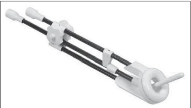
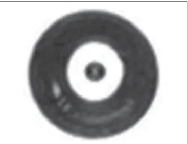
was con-structed specifically for image acquisition. As depicted in Figure 1, CT-/MRI-compatible ring applicators (Nucletron/
Figure 1. CT-/MRI-compatible ring applicator for gynecologic malignancies.
Elekta AB, Stockholm, Sweden) were placed in the gelatin and the catheters were inserted in the applicators.
To determine which solution and image acquisition technique would provide better visualization of the applica-tor lumen, T2-weighted images were acquired with varia-tion of the acquisivaria-tion parameters in a 3 T scanner (Achieva; Philips Healthcare, Eindhoven, the Netherlands) and in a 1.5 T scanner (Signa HDxt; GE Healthcare, Chalfont St. Giles, UK) scanners. The 1.5 T scanner is the default equip-ment for patient imaging. The acquisition parameters were sequence type, echo time (TE), repetition time (TR), slice spacing, and slice thickness (Table 1). The slices were aligned following the tandem axis, parallel to the ring, according to the applicator geometry. Despite the possibility of obtain-ing good contrast on T1-weighted sequences with gado-linium, the tests were conducted only on T2-weighted se-quences, because this is the standard for delineation of gy-necologic tumors(12).
A brachytherapy treatment planning system (Oncentra Master Plan; Elekta AB, Stockholm, Sweden) was used in order to analyze the images visually. The best sequence to visualize the dummies was determined through qualitative analysis of the images, and the process was performed by two observers in order to minimize its variability. Subse-quently, the solutions that, in a qualitative analysis, presented the best contrast in the phantom were tested in four patients in whom 1.5 T MRI was performed with the brachytherapy applicators in place. The study was approved by the local institutional review board and research ethics committee.
Table 1—Parameters used in MRI sequences.
Series 1 2 3 4 5 6 Orientation Coronal Axial Oblique Axial Axial Axial Sequence T2 Cube T2 Cube T2 Cube T2 FSE T2 FSE T2 FSE Slice Spacing (mm) 1.3 1.3 1.3 0.5 1.0 1.5 Thickness (mm) 1.3 1.3 1.3 3.0 3.0 1.5 TR (ms) 1500 1500 1500 5083 7000 9000 TE (ms) 140 140 140 140 140 140
RESULTS
The images were compared in order to determine which solution and MRI sequence promoted the best visualization for applicator reconstruction (Figures 2 and 3). In T2-weighted sequences, the CuSO4 solution presented the highest
contrast (Figure 3), followed by glycerin and saline, both of which presented poor contrast (Figure 2). Comparing these solutions, CuSO4 presented a better contrast than saline and
glycerin. The best combination was an axial T2-weighted fast spin-echo cube sequence—slice spacing = 1.3 mm, slice thick-ness = 1.3 mm, TR = 1500 ms, and TE = 140 ms (Table 1)— used in order to visualize the CuSO4 solution (Figure 4).
Efforts to place a specific slice as the most coincident with the dummy in the ring had to be made in order to achieve better visualization of the dummy. When tested in patients, CuSO4 presented some contrast in T2-weighted sequences
(Figure 5). Although CuSO4 could be visualized in the MRI
Figure 2. MRI scan (T2-weighted sequence) in which the glycerin ring lumen and saline tandem lumen solutions were tested as dummies. The figures show the various acquisitions (detailed in Table 1) for each solution.
Seq 1; Table 1 Seq 2; Table 1 Seq 3;
Table 1
Seq 4; Table 1 Seq 5; Table 1 Seq 6; Table 1
Seq 1; Table 1 Seq 2; Table 1 Seq 3; Table 1
Seq 4; Table 1 Seq 5; Table 1 Seq 6; Table 1
Figure 3. MRI scan (T2-weighted sequence) in which the CuSO4, ring lumen and
tandem lumen solutions were tested as dummies. The figures show the various acquisitions (detailed in Table 1) for each solution.
Figure 4. MRI scan (T2-weighted sequence) in which the CuSO4 dummy is
visu-alized in the ring lumen.
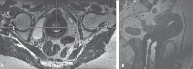
sequences obtained in the patients (Figure 5), the resolu-tion was not sufficient to determine the first dwell posiresolu-tion, mainly in the ring.
DISCUSSION
Image-guided brachytherapy for gynecologic malignan-cies can be performed with CT or MRI scans. However, T2-weighted MRI is the gold standard for defining the tumor volume in patients with cancer of the uterine cervix(12). When the procedure is performed exclusively on the basis of CT scans, tumor coverage is not evaluated appropriately. Nev-ertheless, applicator reconstruction is a key point for a pre-cise and definitive calculation, and manufacturers do not provide MRI-compatible dummies for all kinds of applica-tors. One option to solve this problem is CT-MRI image fusion, although that leads to uncertainties due to image distortions that may be unacceptable, mainly in brachytherapy. In addition, the need to perform two image studies for the same procedure raises the costs, which cannot be neglected. Therefore, applicator reconstruction in MRI scans, where the target volume is best visualized, is mandatory for com-plete 3D treatment.
The CuSO4 solution provided a good signal, with an
acceptable, albeit poor, applicator reconstruction, mainly due to the difficulty in identifying the ends of the catheters. The wax material used to seal the catheter tips does not provide good MRI contrast. In addition, because the catheters are very thin, high precision is needed in order to seal the tips with an exact, known amount of wax, which was not achieved in this experiment. Haack et al.(11) reported that CuSO
4
intensity in the MRI scans. This was, once again, probably due to the very narrow applicator lumen, allowing only a capillary-like catheter to be inserted, with a very low vol-ume of contrast. Recently, the manufacturer developed a new applicator with a larger lumen, which could improve the visualization of contrast inside larger catheters, although only a few hospitals in developing countries can afford to pur-chase this new applicator.
Only three of the six solutions tested were visible in the T2-weighted images generated using the phantom, and only one allowed satisfactory visualization. However, when used in the patients, the contrast was insufficient to reconstruct the applicators appropriately.The differences found between the images generated using the phantom and those acquired in the patients were probably due to the variety of signals generated by the patients themselves, which can make it dif-ficult to identify low-intensity signals like those emanating from very thin catheters.
As an alternative to solve the problem of applicator re-construction, a radiograph of the rings with the dummies provided by the manufacturer (that are only CT-compatible) may be printed in a transparency(13). This is superimposed to the ring in an MRI scan in the same projection as the X-ray. For the tandem, the procedure is much easier, since the distance from the first dwell position to the tandem tip is already known, which allows a very reliable reconstruction to be performed.
The best alternative for applicator reconstruction is the “applicator library” provided by the manufacturer for tan-dem and ring applicators(14). With this tool, it is possible to estimate the location of the first dwell position. The precise determination of this location is not mandatory when using the library, because it is possible to match the entire appli-cator library with the MRI appliappli-cator.
A valid option for evaluating the precision of the recon-struction is to determine the distance from the tip of the tan-dem and the ring to the first dwell position, as an initial reference point for reconstruction in the images. This also
can be a challenge, mainly in relation to the ring, because this reference should be based in the acquired images. In order to evaluate the reliability of the applicator reconstruc-tion, it is recommended that the fixed applicator distances and angles determined previously be compared with those measured in MRI(11). The parameters of interest are the dis-tance between the first dwell position in the tandem and the ring, together with the angle between this distance and the applicator origin, in the coronal section (Figure 6), as well as the distance between the first dwell position in the ring and the applicator origin, together with the angle between this distance and the axis perpendicular to the rectal retrac-tor, in the axial section when the image is aligned with the rectal retractor to verify the ring rotation (Figure 7).
Comparing the different contrast solutions, we were able to identify the best contrast media to be used in MRI. How-ever, with the applicator studied, the results were not satis-factory. The contrast solution may be an option to be used in other situations in which determination of the first dwell position is mandatory, as when different types of applicators, such as those with a larger lumen, are used.
Figure 6. Coronal section showing the distance between the first dwell position in the tandem and the ring (L), as well as the angle (α) between this distance and the applicator origin.
)
Figure 5. MRI scan (T2-weighted sequence) of one patient with the applicators in place and the CuSO4 dummies. A: Axial section: ring. B: Sagittal section: tandem.
CONCLUSIONS
We found CuSO4 to be the best solution for in vitro
visualization of the applicator channels, mainly in T2-weighted images. However, the materials tested presented low signal intensity in the in vivo images and poor
preci-sion in determining the first dwell position, thus precluding appropriate reconstruction, since the applicators studied have a very narrow channel diameter and the dummy manufac-turing process used was not suitable. For clinical purposes, it is necessary to use the library of applicators to guarantee an accurate reconstruction.
REFERENCES
1. International Commission on Radiological Units. Prescribing, re-cording and reporting photon beam therapy (Supplement to ICRU Report 50). ICRU Report 62. Bethesda, MD; 1999.
2. Ji YS, Dong KR, Kim CB, et al. Comparison of dose-volume histo-grams for tomotherapy, linear accelerator-based 3D conformal ra-diation therapy, and intensity-modulated rara-diation therapy. Annals of Nuclear Energy. 2011;38:2569–74.
3. Vieillot S, Azria D, Lemanski C, et al. Plan comparison of volumet-ric-modulated arc therapy (RapidArc) and conventional intensity-modulated radiation therapy (IMRT) in anal canal cancer. Radiat Oncol. 2010;5:92.
4. Alvarez-Moret J, Pohl F, Koelbl O, et al. Evaluation of volumetric modulated arc therapy (VMAT) with Oncentra MasterPlan®
for the treatment of head and neck cancer. Radiat Oncol. 2010;5:110. 5. Jemal A, Bray F, Center MM, et al. Global cancer statistics. CA
Cancer J Clin. 2011;61:69–90.
6. Pötter R, Dimopoulos J, Georg P, et al. Clinical impact of MRI
assisted dose volume adaptation and dose escalation in brachytherapy of locally advanced cervix cancer. Radiother Oncol. 2007;83:148– 55.
7. Pötter R, Georg P, Dimopoulos JC, et al. Clinical outcome of pro-tocol based image (MRI) guided adaptive brachytherapy combined with 3D conformal radiotherapy with or without chemotherapy in patients with locally advanced cervical cancer. Radiother Oncol. 2011;100:116–23.
8. Viswanathan AN, Erickson BA. Three-dimensional imaging in gynaecologic brachytherapy: a survey of the American Brachytherapy Society. Int J Radiat Oncol Biol Phys. 2010;76:104–9.
9. Pavamani S, D’Souza DP, Portelance L, et al. Image-guided brachytherapy for cervical cancer: a Canadian Brachytherapy Group survey. Brachytherapy. 2011;10:345–51.
10. Wang B, Kwon A, Zhu Y, et al. Image-guided intracavitary high-dose-rate brachytherapy for cervix cancer: a single institutional ex-perience with three-dimensional CT-based planning. Brachytherapy. 2009;8:240–7.
11. Haack S, Nielsen SK, Lindegaard JC, et al. Applicator reconstruc-tion in MRI 3D image-based dose planning of brachytherapy for cervical cancer. Radiother Oncol. 2009;91:187–93.
12. Pötter R, Lindegaard J, Kirisits C, et al. A European study in MRI-guided brachytherapy in locally advanced cervical cancer – EM-BRACE. Version 17-01-2008. [cited 2013 Dec 5]. Available from: https://www.embracestudy.dk/UserUpload/PublicDocuments/ EmbraceProtocol.pdf.
13. Berger D, Dimopoulos J, Pötter R, et al. Direct reconstruction of the Vienna applicator on MR images. Radiother Oncol. 2009;93: 347–51.
14. Tanderup K, Hudej R, Lowe G, et al. Applicator reconstruction in cervix brachytherapy. [cited 2013 Dec 5]. Available from: https:// w w w . e m b r a c e s t u d y . d k / U s e r U p l o a d / P u b l i c D o c u m e n t s / Applicator%20reconstruction%20catalogue.PDF.
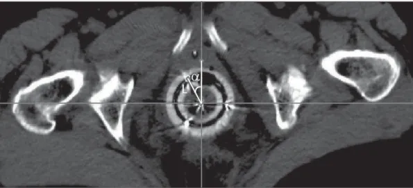
Figure 7. Axial section image showing the distance (L) be-tween the first dwell position in the ring and the applicator ori-gin, as well as the angle (α) between this distance and the axis perpendicular to the rectal retractor, when the image is aligned with the rectal retractor in this plane, to verify the ring rotation.