UNCORRECTED
PROOF
1
2
Trigonometric function used to formulate a multi-nodal
3
finite tubular element
4
E.M.M. Fonseca
a,*, F.J.M.Q. de Melo
b, C.A.M. Oliveira
c5 aDepartment of Applied Mechanics, Campus de Sta. Apolo´nia Ap. 1134, Polytechnic Institute of Braganc¸a,
6 5301-857 Braganc¸a, Portugal
7 bDepartment of Mechanical Engineering, University of Aveiro, 3810-193 Aveiro, Portugal
8 cDepartment of Mechanical Engineering, Faculty of Engineering of University of Porto, 4200-465 Porto, Portugal 9
10 Abstract
11 It is presented an alternative formulation to solve the problem of the deformation analysis for tubular element under
12 pinching loads. The solution is based on a new displacement field defined from a total set of trigonometric functions. The
13 solution is developed in a multi-nodal finite tubular ring element with a total of eight degrees of freedom per section
con-14 sidered. The purpose of this paper is to provide an easy alternative formulation when compared with a complex finite shell
15 element or beam element analysis for the same application. Several case studies presented have been compared and
dis-16 cussed with numerical analyses results reported by other authors and the results obtained with a shell element from a
Cos-17 mos/M
programme.
18 2006 Published by Elsevier Ltd.
19 Keywords: Multi-nodal; Finite tubular ring element; Pinching loads; Trigonometric functions 20
21 1. Introduction
22 Structural design methodologies for pipelines systems start to be used, especially when it is expected that 23 enhancements in the design process will lead to more cost effective and durable designs. These piping elements 24 exhibit complex deformations fields given their toroidal geometry and the multiplicity of the configuration of 25 external loads. Mathematical and experimental models which permit to verify the flexibility of pipe systems 26 were published for a long time by some researchers working in this scope: (von Ka´rman, 1911; Vigness,
27 1943; Cheng and Thailer, 1970) and more recently (Thomson, 1980; Wilczek, 1984; Bathe and Almeida,
28 1982). News models used for stress and displacements fields determination, under mechanical or thermal 29 loads, were recently formulated using numerical techniques with new finite elements by Melo and Castro
30 (1992), Fonseca et al. (2002, 2005). Studies on circular cylindrical shells under concentrated forces have been
31 presented by many researchers using curved beam, shell and solid elements (Kouhia and Stenberg, 2000;
Gob-0093-6413/$ - see front matter 2006 Published by Elsevier Ltd.
doi:10.1016/j.mechrescom.2006.06.008
* Corresponding author. Tel.: +351 273303155; fax: +351 273313051.
E-mail addresses:[email protected](E.M.M. Fonseca),[email protected](F.J.M.Q. de Melo),[email protected](C.A.M. Oliveira). Mechanics Research Communications xxx (2006) xxx–xxx
www.elsevier.com/locate/mechrescom
MECHANICS
UNCORRECTED
PROOF
32 etti and Nascimbene, 2001). Shell element formulations based on the so-called degenerate models introduced
33 byAhmad et al. (1970)have been used due their ability in moderately thick and thin plate or shell elements A 34 long report about the development of finite shell or plate elements with emphasis on innovations was pre-35 sented byMacNeal (1998). News formulations of solid element were presented for the linear and nonlinear 36 analysis of thin-walled structures byKim et al. (2004). The particular case of the formulation of cylindrical 37 shells using ring elements has a straightforward contribution from On˜ate (1992), where this author used a 38 combined formulation for the displacement field dealing with fourier series along the circumference and alge-39 braic shape functions along the axial direction. Analysis of a circular ring is reasonable for the structural 40 design of most buried pipes when they can withstand the three most basic loads: internal pressure, transpor-41 tation/installation and external pressure (Watkins and Anderson, 2000). The ring deflection is a potential per-42 formance limit for transportation/installation of pipes. The aim of this study is to develop an alternative 43 numerical method and present an experimental work for pipes analysis when used in underground sewerage 44 without internal pressure or when submitted to mechanical loads imposed during transportation or an instal-45 lation. Satisfactory results for circular rings can be obtained by several different methods. This work presents 46 an alternative formulation based on one finite element with two nodal sections used to simulate pinching loads 47 in the referred situations and analyse the structural mechanics of pipes in linear bending conditions.
48 2. Finite element formulation: assumptions and deformation model
49 The geometric parameters considered for this element definition are: the length of the pipes, the wall thick-50 nesstand the mean section radius of the piper.Fig. 1shows the essential parameters and the degrees of free-51 dom used to define the finite tubular ring element.
52 The basic kinematics assumptions refer to the deformation of a thin shell as used in a small-defection anal-53 ysis. The assumptions in the problem formulation of in-plane bending are: the shell is thin, this meaning that 54 the normal to the shell surface does not distort and the transverse section is inextensible, not including pres-55 sure effects. The strain analysis and curvature geometry field of a non-symmetrically deformed cylindrical shell 56 may be founded on the behaviour of plates and shells of revolution. Kinematics expressions relating the mid-57 surface strains are expressed by(1–3)and the curvatures and twist by(4–5).
58
ess ¼ ou
os; ehh¼
1
r
ov
ohþw
and mash¼
1
r
ou
ohþ ov
os ð1–3Þ
60 60 61
vhh¼ 1
r2
ov ohþ
o2w oh2
and vsh¼2
r
ov osþ
o2w os@h
ð4–5Þ 63
63
64 whereessis the longitudinal membrane strain,ehhis the meridional curvature from ovalization,cshthe shear 65 strain,vhhis the meridional curvature variation from ovalization andvshthe twist variation.
66 A simplified theory is useful under certain conditions and is applicable to a variety of shells forms. How-67 ever, we shall deal only with the inextensional deformation of circular cylindrical shells. This theory is often
UNCORRECTED
PROOF
68 preferred when shell structures resist loading principally through bending action. Such cases include a cylinder 69 subjected to loads without axial symmetry and confined to a small circumferential portion and there is con-70 siderable bending caused by changes in curvature, but no stretching of midsurface length. Deformations of 71 these types are thus described as inextensional referred byUgural (1981). In this shell theory, the midsurface 72 in-plane strain components given by Eqs.(1–3)are taken to be zero. We realise from Eq.(1)that u depends on 73 h and Eq.(2)leads to:
74
w¼ ov=oh ð6Þ
76 76
77 3. The displacement field for the finite tubular ring element
78 The displacement filed proposed characterises a uniform ovalization in the tube and a variation along the 79 shell length. To obtain the shape functions a displacement field has been considered in the normal radial direc-80 tion. As represented inFig. 1the element presents five nodes under symmetric conditions make possible stud-81 ies in-plane bending. So, only a half of a ring section is needed to consider when trigonometric even functions 82 are used. The initial radial displacement used to define the ovalization effect must be calculated using the trig-83 onometric polynomial approximation. A formulation based on trigonometric functions is used and eight 84 parameters are necessary to define the transversal displacement field approximated by:
wðs;hÞ ¼X 9
i¼2
ai1icosihþS
X9
i¼2
bi1isinih ð7Þ
86 86
87 Using simple differential equation from beam bending theory the transverse displacement can be calculated:
vðs;hÞ ¼ X 9
i¼2
ai1sinihS
X9
i¼2
bi1cosih ð8Þ
89 89
90 The rotation field is considered using the derivative function of the transverse displacement field:
uðs;hÞ ¼1
r
ow oh ¼
1
r
X9
i¼2
ai1i2sinih
S r
X9
i¼2
bi1i2cosih ð9Þ
92 92
93 The unknown parametersaiare determined by imposing boundary conditions according to the ring element
94 sectioniandjconsidered, resulting a system of equations to be solved. The degrees of freedom considered in 95 the proposed element are: node 1 and 5 are the transversal displacement and their derivatives vanish, for nodes 96 2 at 4 have a radial displacement and one derivative function. A system with 16 equations is solved foriandj 97 section of the ring element and shapes functions are obtained:
98
fdg ¼ ½B0faig ð10Þ
100 100
101 with {d}T= {W1i W2i u2x W3i u3i W4i u4i W5i W1j W2j u2j W3j u3j W4j u4j W5j}T
102 which represents the global displacement field for transversal and rotation degrees of freedom in the semi no-103 dal ring and [B0] is constant matrix that results from the imposed boundary conditions. For node 1 the trans-104 versal displacement is equal to one and all others equal to zero. The first shape function appears and is called 105 N1i. With imposed Eq.(6)we determine the shape functionBN1i. The same has been used for all others nodes.
106 The unknown constants are determined inverting the system equation(10). The first shape function is repre-107 sented by Eq.(11). With these conditions, a new shape functions are determined and the generic local displace-108 ments field for in-plane finite element formulation are given by Eqs.(12) and (13).
109
N1i¼
3
16cos 2ð hÞ þ 5
32cos 3ð hÞ þ 1
8 cos 4ð hÞ þ 3
32cos 5ð hÞ þ 1
16cos 6ð hÞ þ 9
64cos 7ð Þ þh 1
8cos 8ð hÞ
þ 7
64cos 9ð hÞ
s 3
16
cos 2ð hÞ
L þ
5 32
cos 3ð hÞ
L þ
1 8
cos 4ð hÞ
L þ
3 32
cos 5ð hÞ
L þ
1 16
cos 6ð hÞ
L
þ 9
64
cos 7ð hÞ
L þ
1 8
cos 8ð Þh
L þ
7 64
cos 9ð hÞ
L
ð11Þ
UNCORRECTED
PROOF
v sð ;hÞ ¼BN1iW1iþBN2iW2iþBN02iu2iþBN3iW3iþBN03iu3iþBN4iW4iþBN04iu4iþBN5iW5i
þBN1jW1jþBN2jW2jþBN02ju2jþBN3jW3jþBN03ju3jþBN4jW4jþBN40ju4jþBN5jW5j ð12Þ
114 114 115
w sð;hÞ ¼N1iW1iþN2iW2iþN02iu2iþN3iW3iþN03iu3iþN4iW4iþN04iu4iþN5iW5iþN1jW1j
þN2jW2jþN02ju2jþN3jW3jþN03ju3jþN4jW4jþN04ju4jþN5jW5j ð13Þ
117 117
118 All other shape functions are determined in the same form. This formulation presents a simple formula for 119 calculation of the displacement field for the tangential and transversal displacement under a shell element:
fv wgT ¼ ½N fdg ð14Þ
121 121
122 As referred previously, the mechanical deformation model considers that the pipe undergoes a semi-membrane 123 strain field by Eqs.(4–5). The typical use of the principle of virtual work leads to the system of algebraic equa-124 tions. Having solved the system of algebraic equations, the displacement field is obtained for all the nodes of 125 the finite tubular ring element.
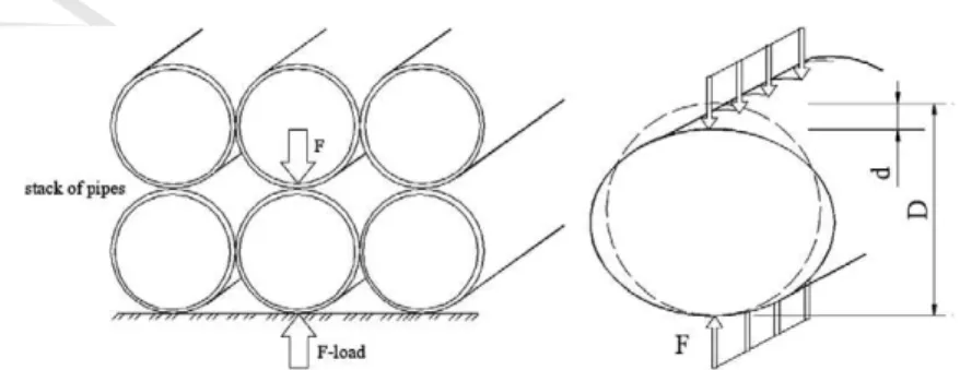
126 4. Deformation models on pipes design
127 One step of design is resistance to loads imposed on the pipe during transportation and installation. The 128 most common load is the diametral F-load, seeFig. 2. This load appears when pipes are stacked or when soil 129 is compacted on the sides or on top of the pipe (Watkins and Anderson, 2000). If yield strength of the pipe 130 material is exceeded due the F-load, either the pipe wall will crack or the cross section of the pipe will perma-131 nently deform. Either of these deformations, a crack is a deformation but unacceptable. The yield strength 132 may possible be a performance limit even though the ring does not collapse.
133 The limit of the F-load for some manufactures pipes is based on the maximum allowable ring deflection 134 based on Eq.(15). For the design process of the pipe transportation/installation loads, the maximum allow-135 able F-load for plain pipes is calculated by the expression16(Watkins and Anderson, 2000).
136
d0¼d=D and F ¼ ðprcD=3Þðt=DÞ2 ð15–16Þ
138 138
139 The ring defection for mechanical analysis of thin-walls rings with symmetrical loads is given by:
d0¼0:0186ðFD2=EIÞ ð17Þ
141 141
142 whered00represents the ring deflection,dthe decrease in diameter,Dthe mean diameter of the pipe,tthe wall 143 thickness for plain pipe,rcis the yield strength andEIthe wall stiffness per unit of length of the pipe.
144 5. Case studied 1: pinched cylinder
145 The pinched cylinder problem tests the ability of simulation to model complex bending and membrane 146 states. In the pinched cylinder, the shear-locking phenomenon is more detrimental to the solution accuracy 147 than membrane-locking. A severe problem for most finite elements is the locking which can appear as shear 148 or membrane locking, as reported byAndelfinger and Ramm (1992). Transverse shear locking can occur in
UNCORRECTED
PROOF
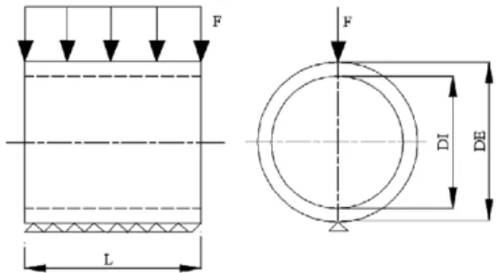
149 shear deformable beam, plate and shell elements or solid elements if these are applied to the analysis of thin-150 walled structures. Transverse shear locking is one of the most important locking effects because it can essen-151 tially exclude an analysis with a reasonable amount of numerical effort in practical applications. This effect is 152 significant only if there is a certain in-plane bending deformation of the structure. Shear locking occurs where 153 the shear stiffness is a lot higher than the bending stiffness. Membrane locking can occur in thin shells or 154 curved elements where the membrane stiffness is a lot higher than the bending stiffness. Researchers use the 155 pinched cylinder problem as a benchmark test to assess the performance of curved beam or shells elements. 156 The problem here presented, concerns a pinched cylinder with rigid end diaphragms, subjected to diametrical 157 load as shown inFig. 3, proposed byMacNeal and Harder (1985)and studied by a several authors. The geo-158 metric configuration of the cylinder is the length (L= 600 in.), the radius (r= 300 in.) and wall thickness 159 (t= 3 in.). The elastic modulus was taken (E= 3·106psi) and Poisson’s ratio (t= 0.3). Only a half of the
160 cylinder is modelled due the geometry and load symmetry. The point load applied is equal (P= 1/2 lb). 161 The reference displacement, as reported by Dvorkin and Bathe (1984), Kouhia and Stenberg (2000) and 162 the exact deflection at the load point is equal (0.18248E4 in.), usingwexact= 164.24(P/Et). This is known
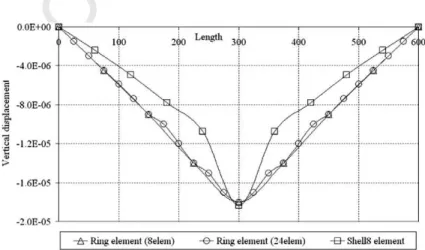
163 as a benchmark result where there is a bending dominant behaviour in the thin shell limit. Thus transverse 164 shear and membrane locking occurs as the shell becomes thinner.Fig. 4represents the vertical displacement 165 along length of cylinder obtained with our formulation with two different meshes and shell element from
Cos-166 mos/M
.
167 Table 1shows the normalized vertical displacement under the load of the pinched cylinder modelled using
168 our proposed element and other references. Fig. 5shows the vertical displacement using Cosmos/M . The 169 solution obtained by the ring element does not exceed the analytical solution because it does not include trans-170 verse shear deformation. Thus, the numerical results of the present element are also compared with another 171 solution, using a shell element from Cosmos/M
which allows transverse shear deformation. The result of the 172 displacement using ring element performs well even in the coarse mesh configurations. The small slenderness
Fig. 3. Geometry of a pinched cylinder loaded.
UNCORRECTED
PROOF
173 ratio (t/r= 1/100) of the cylinder is chosen to demonstrate the capability of our ring element to overcome 174 shear and membrane-locking phenomena.
175 6. Case studied 2: ring deformation
176 The studied case of a ring deformation is shown inFig. 6, representing a tubular steel ring structure sub-177 mitted to a F-load along the length (L= 170 mm) and free ends. The tubular section presents an external 178 diameter (DE = 165 mm) and an internal diameter (DI = 155 mm). The elasticity modulus is (E= 2.1 GPa) 179 and the Poisson coefficient is equal to (t= 0.3). The theoretical value of the decrease diameter (d) on the 180 top section and the lateral displacement at middle of section (u) can be obtained using the Castiglino’s 181 theorem:
182
Table 1
Normalized displacement under the load
Meshes wFEM/wexact
5·5a 0.5100
10·10a 0.8300
20·20a 0.9600
4·4b 1.1769
8·8b 0.9912
16·16b 1.0059
Ring element (8 or 24 elements) 0.9864
Shell8 element Cosmos/M
(400 elements) 1.0060
a Dvorkin and Bathe (1984). b
Kouhia and Stenberg (2000).
Fig. 5. Vertical displacement using Cosmos/M .
UNCORRECTED
PROOF
d ¼ Pr
3ðp28Þ
8pEI þ
Prp
8GAmþ
Prp
8EA
ð18Þ
u¼Pr 3ð4
pÞ
4pEI þ
Pr
4GAm
Pr
4EA ð19Þ
184 184
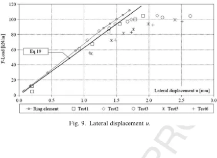
185 In this case: I=Lt3/12, A=tL,G=E/2(1 +m) andm= 9/10 is the correction factor. The transversal dis-186 placement at the top and the lateral displacement will be analysed using the experimental method, analytical 187 solutions and numerical results obtain with the developed finite ring element. The experimental setup used is 188 represented inFig. 7. The loading system is implemented by a hydraulic jack and load cell, and both displace-189 ments are obtained with a data acquisition system using two LVDT’s.
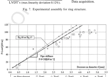
190 Fig. 8represents the decrease displacement in diameter function of the F-Load, obtained with five
exper-191 imental tests. The elastic part of the experimental results may be compared with the results of Eq.(15)or(18) 192 and numerical results from the finite ring element.Fig. 9represents the lateral displacement measured for the 193 same five experimental tests. The elastic part of the experimental results may be compared with the results 194 provided by Eq.(19)and the numerical results obtained from the finite ring element.
195 The experimental tests present satisfactory results when compared with the numerical and analytical solu-196 tion. Increasing loading test will gradually increase scattered data results. Numerical results approach the the-197 oretical curve, while the experimental results are positioned below this curve. The experimental results present 198 a non-linear trend for higher load values. Linear data can be useful to determine pipe stiffness, defined as resis-199 tance to ring deflection.
Fig. 7. Experimental assembly for ring structure.
UNCORRECTED
PROOF
200 7. Conclusion
201 A computer program based on the linear theoretical formulation described was developed for the analysis 202 and determination of the transverse displacement field along ring section of tubular pipes. To validate the ele-203 ment accuracy, numerical results were presented with a good agreement with other authors, analytical solu-204 tions and numerical analysis using Cosmos/M
. The presented solution has performed well even with 205 coarse element meshes, and appears as a simple and easy-to-handle alternative to the use of shell or beam finite 206 elements due the capability and effectiveness of this element. The presented formulation using a multi-nodal 207 element under symmetric conditions makes possible to determine a displacement field under shell surface for 208 in-plane bending problems. A pre-processor for generate one-dimensional meshes with two sections (iandj) 209 per element is only necessary. The Cosmos/M
shell element presents eight nodes per element, and a more 210 refined three-dimensional mesh is necessary. The ring element exhibits excellent behaviour for all configura-211 tions in linear bending conditions like all shell elements, when using a small slenderness ratio between thick-212 ness and radius.
213 References
214 Ahmad, S., Irons, B.M., Zienkiewicz, O.C., 1970. Analysis of thick and thin shell structures by curved finite elements. Int. J. Numer. Meth. 215 Eng. 2, 419–451.
216 Andelfinger, U., Ramm, E., 1992. An Assessment of hybrid-mixed four-node shell elements. In: Rammerstorfer, F.G. (Ed.), Nonlinear 217 Analysis of Shells by Finite Elements. Springer-Verlag, New York, pp. 31–45.
218 Bathe, K.J., Almeida, C.A., 1982. A simple and effective pipe elbow element – Pressure stiffening effects. J. Appl. Mech. 49, 914–916. 219 Cheng, D.H., Thailer, M.J., 1970. On the bending of curved circular tubes. ASME J. Eng. Ind. B 92 (1), 62–66, B.
220 Dvorkin, E., Bathe, K.J., 1984. A continuum mechanics based four-node shell element for general non-linear analysis. Eng. Comput 1, 77–
221 88.
222 Fonseca, E.M.M., Melo, F.J.M.Q., Oliveira, C.A.M., 2002. Determination of flexibility factors on curved pipes with end restraints using a 223 semi-analytic formulation. Int. J. Pressure Vessels Piping 79 (12), 829–840.
224 Fonseca, E.M.M., Melo, F.J.M.Q., Oliveira, C.A.M., 2005. The thermal and mechanical behaviour of structural steel piping systems. Int. 225 J. Pressure Vessels Piping 82 (2), 145–153.
226 Gobetti, A., Nascimbene, R., 2001. Elasto-plastic, nonlinear analysis of a locking-free shear/flexible curved beam element. In: ECCM-227 European Conference on Computational Mechanics, Poland.
228 Kim, K.D., Liu, G.Z., Han, S.C., 2004. A resultant 8-node solid-shell element for geometrically nonlinear analysis. Comp. Mech. 35 (5), 229 315–331.
230 Kouhia, R., Stenberg, R., 2000. A simple linear nonconforming shell element. In: IASS-IACM 2000, Fourth International Colloquium on 231 Computational of Shell Spatial Structures, Greece.
232 MacNeal, R.H., 1998. Perspective on finite elements for shell analysis. J. Finite Elem. Anal. Des. 30, 175–186.
233 MacNeal, R.H., Harder, R.L., 1985. A proposed standard set of problems to test finite element accuracy. J. Finite Elem. Anal. Des. 1, 3–
234 20.
235 Melo, F.J.M.Q., Castro, P.M.S.T., 1992. A reduced integration Mindlin beam element for linear elastic stress analysis of curved pipes 236 under generalized in-plane loading. Comp. Struct. 43 (4), 787–794.
UNCORRECTED
PROOF
237 On˜ate, Eugenio., 1992. Ca´lculo de Estructuras por el Me´todo de Elementos Finitos. Structure Calculation using the Finite Element 238 Method. CIMNE Edition, The Polythecnic University of Calaunia, chapts 10, a2 and 14 (in spanish).
239 Thomson, G., 1980. The influence of end constraints on pipe bends. Ph.D. thesis, University of Strathclyde, Scotland, UK. 240 Ugural, A.C., 1981. Stresses in Plates and Shells. McGraw-Hill Inc.
241 Vigness, I., 1943. Elastic properties of curved tubes. ASME 65, 105–120.
242 von Ka´rman, Th., 1911. U¨ ber die formanderung dunnwaindiger rohre insbesondere federnder ausgleichrohre. Zeits V.D.I. Band 55, 889–
243 1895.
244 Watkins, R.K., Anderson, L.R., 2000. Structural Mechanics of Buried Pipes. CRC Press, New York.