obtained for all other uses, in any current or future media, including reprinting/republishing
this material for advertising or promotional purposes, creating new collective works, for resale
or redistribution to servers or lists, or reuse of any copyrighted component of this work in
other works.
L. M. R. Oliveira, A. J. M. Cardoso: "Intermittent turn‐to‐turn winding faults diagnosis in power
transformers by the on‐load exciting current Park's Vector Approach", Proc. of the 2008
International Conference on Electrical Machines (ICEM 2008), CD‐ROM, 6 pp., Vilamoura,
Portugal, September 6‐9, 2008.
http://ieeexplore.ieee.org/xpls/abs_all.jsp?arnumber=4800049
Intermittent Turn-to-Turn Winding Faults Diagnosis
in Power Transformers by the On-Load Exciting
Current Park's Vector Approach
Luís M. R. Oliveira
1, 2and A. J. Marques Cardoso
21Escola Superior de Tecnologia da Universidade do Algarve; Campus da Penha; P – 8005-139 Faro, Portugal Tel: (+351) 289800100, fax: (+351) 289888405
e-mail: [email protected]
2Universidade de Coimbra, FCTUC/IT; Departamento de Engenharia Electrotécnica e de Computadores; Pólo II - Pinhal de Marrocos; P – 3030-290 Coimbra, Portugal
Tel: (+351) 239796232, fax: (+351) 239796247 e-mail: [email protected]
Abstract- This paper presents the application of the on-load exciting current Park's Vector Approach for diagnosing perma-nent and intermittent turn-to-turn winding faults in operating power transformers. A digital model for the simulation of the be-havior of three-phase transformers affected by the presence of winding faults is also proposed. Experimental and simulated re-sults demonstrate the effectiveness of the proposed diagnostic technique, which is based on the on-line monitoring of the on-load exciting current Park's Vector patterns.
I. INTRODUCTION
Power transformers are essential devices in a transmission and distribution system. Failure of a power transformer may cause a break in power supply and loss of profits. Therefore, it is of great importance to detect incipient failures in power transformers as early as possible, so that they can be switched off safely and improve the reliability of power systems [1]. As a result, it is quite obvious the need for the development of on--line diagnostic techniques that would aid in transformers maintenance. A survey of the most important methods, actu-ally in use, for condition monitoring and diagnostics of power and distribution transformers, presented in [2], stresses the need for the development of new diagnostic techniques, which can be applied without taking transformers out of service, and which can also provide a fault severity criteria, in particular for determining transformers winding insulation faults.
The most difficult transformer winding fault for which to provide protection is the fault that initially involves only one turn [3]. Initially, the insulation breakdown leads to internal arcing, which results into a low current, high impedance fault [4]. Usually, this incipient inter-turn insulation failure does not draw sufficient current from the line to operate an ordinary overload circuit-breaker or even more sensitive balanced pro-tective gear [5]. This turn-to-turn fault will then progress, with random propagation speed, involving additional turns and lay-ers, leading to a high current, low impedance fault, [6]. The transformer will, in fact, be disconnected from the line auto-matically when the fault has extended to such degree as to
em-brace a considerable portion of the affected winding [5]. As stated above, the initial turn-to-turn insulation defect leads to an arcing fault, which is a dangerous form of a short--circuit, that may have a low current magnitude. Arcing faults usually cause a damage that is limited to the fault area, and pose a great danger to the transformer [7]. When the voltage potential between the affected turns breaks down the insulation a spark discharge takes place. The arc ignition and extinction depends on this threshold voltage [8], [9], resulting on a fault of intermittent nature. The behavior of the transformer wind-ing currents under the occurrence of this type of fault should be clearly understood, in order to allow the detection of the failure in its incipient stage.
Previous research, concerning the use of the Park's Vector Approach, has demonstrated the effectiveness of this non inva-sive technique for diagnosing malfunctions in operating three- -phase induction motors, power electronics and adjustable speed drives [10]. Preliminary experimental results, presented in [2], concerning the use of the supply current Park's Vector Approach, have also demonstrated the effectiveness of this technique for diagnosing the occurrence of inter-turn insulation faults in the windings of operating three-phase transformers. The on-line diagnosis is based on identifying the appearance of an elliptic pattern, corresponding to the transformer supply cur-rent Park's Vector representation, whose ellipticity increases with the severity of the fault and whose major axis orientation is associated to the faulty phase. However, with this approach, it is difficult to discriminate between unbalanced loads and winding faults. To overcome this difficulty, an improved diag-nostic technique was implemented, which consists in the analysis of the on-load exciting current Park's Vector pattern, and therefore unaffected by the transformer's load conditions.
The experimental study of winding inter-turn short-circuits occurrence presents some difficulties, mainly due to the high magnitudes of the faulty currents involved, which can damage the test transformer. Therefore, a detailed analysis of these phenomena can be better investigated by the use of a suitable digital simulation transformer model. For that purpose, a
cou-2 pled electromagnetic transformer model was developed [11], which is based on the combination of both magnetic and elec-tric lumped-parameters equivalent circuits, allowing for the modeling and simulation of the transformer in its natural tech-nology.
With the aid of this transformer model, the on-load exciting current Park's Vector Approach will be applied for diagnosing the occurrence of permanent and intermittent winding insula-tion faults, which is the scope of this paper.
II. EXPERIMENTAL SETUP
For the experimental investigation a three-phase, two wind-ing, three-leg transformer, of 10.3 kVA, 230/132 V, was used. In each winding of the transformer there are five additional tappings connected to the coils, allowing for the introduction of shorted turns at several locations in the winding, as shown in Fig. 1, for the phase R of the transformer primary winding.
The permanent faults are introduced in the test transformer by connecting a shorting resistor at the terminals of the af-fected turns. The value of this resistor was chosen so as to cre-ate an effect strong enough to be easily visualized, but simulta-neously big enough to limit the short-circuit current and thus protecting the test transformer from complete failure when the short is introduced.
If the fault occurs in the primary winding, the short-circuited turns act as an autotransformer-load on the winding, as shown in Fig. 2(a). However, if the fault takes place on the secondary winding, the short-circuited turns act as an ordinary double winding load, Fig. 2(b) [5].
The arcing faults are introduced in the test transformer by connecting a custom built power electronics board, at the ter-minals of the affected turns. Basically, the power electronics circuit consists of two modules, each one with an IGBT in se-ries with a power diode, connected in anti-parallel, as shown in Fig. 3(a). The arc ignition and extinction depends on the threshold voltage, which is regulated by the delay time and the conduction time (pulse width) of the IGBT's, Fig. 3(b). Again,
U UA UB UC UD UE U1 2 turns 2 turns 2 turns 2 turns 72 turns 72 turns
Fig. 1. Location of the tappings for transformer primary winding (phase R).
1N v a N 1 i 2 N 4 i b i x i 1 L R b N 1 N σa φ b σ φ 1 φ sh R 1 φ a N 1 i b i x i b N 1 N a σ φ b σ φ sh R 4 i 1 L R N2 1N v (a) (b)
Fig. 2. Equivalent circuits for a fault occurring in the (a) primary winding; (b) secondary winding.
an auxiliary shorting resistor was used, to maintain the faulty current within safe values.
III. DIGITAL SIMULATION OF WINDING INTER-TURN SHORT-CIRCUITS
For winding fault studies, an open-structure transformer model is necessary, i.e., a model in which it would be possible to manipulate the windings arrangement. The coupled electro-magnetic model, allowing for the modeling and simulation of the transformer in its natural technology, so that the cause-and- -effect relationships can be closely investigated, [12], becomes the natural choice for the analysis of transformer internal faults, [11].
The coupled electromagnetic transformer model consists in the combination of both magnetic and electrical equivalent cir-cuits (Fig. 4 and Fig. 5, respectively), in order to obtain the flux-current (λ-i) relationships:
= ⋅
L i
λ
(1) i R v λ dt= − ⋅ d (2) Faulty windingIntermittent Fault Equivalent Circuit
sh
R
Delay time and pulse width adjustment 2 T 1 T x i Signal isolation and gate drive circuit Signal isolation and gate drive circuit in i b i Zero cross detection and pulse synchro-nization synchronization v Delay time Pulse width 1 GE T v 2 GE T v t t (a) (b)
Fig. 3. (a) Intermittent fault equivalent circuit with a power electronics board. (b) Gate signals of the IGBT's.
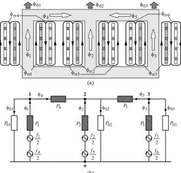
01 φ φ02 4 φ φ5 03 φ 1 σ φ 4 σ φ 2 σ φ 5 σ φ 6 σ φ 3 σ φ 2 φ 1 φ φ3 (a) 3 φ 2 φ 1 φ 4 φ φ5 01 φ φ02 φ03 01 P P1 4 P 2 P 5 P 2 1 f 2 2 f 02 P P3 P03 2 3 f n 1 2 3 2 4 f 2 5 f 2 6 f (b)
Fig. 4. (a) Flux distribution in a three-phase, three-limb, two-winding, core-type transformer, assuming a slightly greater magnetomotive force in the inner windings. (b) Equivalent magnetic circuit.
The faults are introduced in the model by dividing the af-fected winding in two parts, which represent the healthy sub-winding and the faulty subsub-winding, as shown in the equivalent circuits of Fig. 2. The pertinent fault equivalent circuit is then introduced in the magnetic equivalent circuit (leading to three magnetomotive forces in the faulty phase, Fig. 6) and in the electric equivalent circuit (leading to other several changes, Fig. 7). A detailed description of the model implementation is given in [11], [13].
For the simulation of arcing defects a combination of both healthy and faulty models of the transformer is used. The model of the winding fault is only applied when the spark dis-charge takes place.
IV. INTERMITTENT FAULT CHARACTERIZATION
In the results presented in this paper an YNyn0 transformer winding connection and a balanced resistive load were used.
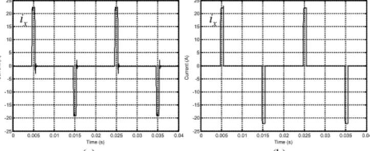
Fig. 8(a) presents the experimental arc current waveform, ix,
for the case of four intermittent shorted turns in the phase R of the primary winding. In order to clearly visualize the transient phenomena, a pulse width of approximately 800 μs was cho-sen. Fig. 8(b) presents the corresponding simulated result, which is identical to the experimental one. For the same con-ditions mentioned above, both experimental and simulated
n R S T 1 i 2 i 3 i N 4 i n 5 i 6 i 2 3 1 5 6 4 3 L R 1 L R 2 L R
Fig. 5. Simplified equivalent electric circuit for the case of an YNyn0 connec-tion and a balanced resistive load.
3 φ 2 φ 1 φ 4 φ φ5 01 φ φ02 φ03 1 2 3 2 a f 2 2 f 2 3 f n 2 4 f 2 5 f 2 6 f 2 b f 01 P P1 P2 P02 P3 P03 4 P P5
Fig. 6. Equivalent magnetic circuit for the case of a primary-side faulty wind-ing (phase R). n 4 i n 5 i 6 i 2 i 3 i N a N Nb sh R 1 i R S T RL3 1 L R 2 L R 5 6 4 2 3 1
Fig. 7. Equivalent electric circuit for the case of a primary-side faulty winding (phase R).
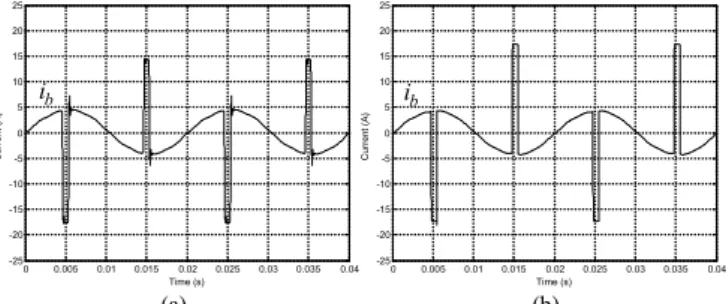
primary-side currents waveforms are shown in Fig. 9(a) and 9(b), respectively, which are in relatively good agreement (no-tation as per Fig. 7). The arc current is reflected to the primary-side, leading to an increment in the magnitude of the current in the affected winding, as compared to a healthy condition. In the presence of the primary winding inter-turn short-circuits, the secondary-side currents do not present any relevant change as compared to the transformer's healthy operation, remaining an approximately balanced three-phase system, as shown in Fig. 10. The current waveform in the shorted turns, ib, is shown in Fig. 11. When ix is zero, the
current in the defective turns is equal to i1. During the arc discharge, ib presents a deep notch, since ib = i1– ix.
The input current in the affected winding can be divided into three terms:
1 4 exc1 x
i = +i′ i + (3) i′
where i'4 is the secondary winding current referred to the pri-mary-side, iexc1 is the excitation current and i'x is the current in
the fault impedance, also referred to the primary-side.
Obviously, the first two terms are related with the healthy operation of the transformer, being the third a result of the shorted turns. The faulty current is reflected to the pri-mary-side through the turns ratio between the number of shorted turns, Nb, and the total number of turns of the
pri-mary-side winding, N1:
1
x x b
i′ = ×i N N (4)
As a result, the increase in the magnitude of the primary-side winding current, due to an incipient insulation defect, with
0 0.005 0.01 0.015 0.02 0.025 0.03 0.035 0.04 -25 -20 -15 -10 -5 0 5 10 15 20 25 Time (s) C u rr en t ( A ) 0 0.005 0.01 0.015 0.02 0.025 0.03 0.035 0.04 -25 -20 -15 -10 -5 0 5 10 15 20 25 Time (s) C u rr en t ( A ) x i ix (a) (b)
Fig.8. Arc current waveform for the case of a primary-side fault: (a) experi-mental; (b) simulated. 0 0.005 0.01 0.015 0.02 0.025 0.03 0.035 0.04 -6 -4 -2 0 2 4 6 Time (s) C u rre nt ( A ) 1 i i2 i3 0 0.005 0.01 0.015 0.02 0.025 0.03 0.035 0.04 -6 -4 -2 0 2 4 6 Time (s) C u rre nt ( A ) 1 i i2 i3 (a) (b)
Fig. 9. Primary-side currents waveforms for the case of an intermittent primary-side fault: (a) experimental; (b) simulated.
4 0 0.005 0.01 0.015 0.02 0.025 0.03 0.035 0.04 -8 -6 -4 -2 0 2 4 6 8 Time (s) Cu rr e nt ( A ) 4 i i5 i6 0 0.005 0.01 0.015 0.02 0.025 0.03 0.035 0.04 -8 -6 -4 -2 0 2 4 6 8 Time (s) Cu rr e nt ( A ) 4 i i5 i6 (a) (b)
Fig. 10. Secondary-side currents waveforms for the case of an intermittent primary-side fault: (a) experimental; (b) simulated.
0 0.005 0.01 0.015 0.02 0.025 0.03 0.035 0.04 -25 -20 -15 -10 -5 0 5 10 15 20 25 Time (s) C urren t ( A ) 0 0.005 0.01 0.015 0.02 0.025 0.03 0.035 0.04 -25 -20 -15 -10 -5 0 5 10 15 20 25 Time (s) C urren t ( A ) b i ib (a) (b)
Fig.11. Current waveform in the shorted turns for the case of a intermittent primary-side fault: (a) experimental; (b) simulated.
only a few turns involved, is small, even if the faulty current is large, and it is very likely that the fault remain undetected by the protection devices, until it progresses to a catastrophic fail-ure. The severity of the fault depends not only on the number of shorted turns, but also on the value of the faulty current, which is limited by the fault impedance.
For the same aforementioned conditions, but now for the case of four intermittent shorted turns in the phase R of the
transformer secondary winding, the current waveforms in the shorting resistor, in the primary and secondary-side windings of the affected phase and in the shorted turns are presented in Fig. 12, 13 and 14, respectively. The additional load produced by the shorted turns also results into an increment in the mag-nitude of the correspondent primary-side winding current, as compared to a healthy condition. Again, the line currents of the secondary-side do not suffer any significant change with the introduction of the defect. In comparison with the case of a primary-side fault, the only significant difference is the current waveform in the shorted turns, which is now given by ib = i4–ix,
Fig. 14, and it takes larger values than the arc current.
The presence of the fault has the same end effect on the primary-side current, irrespective of whether the fault is located on the primary or on the secondary-side, and (3) and (4) remain valid for both of these conditions.
V. WINDING FAULTS DETECTION BY THE ON-LOAD EXCITING CURRENT PARK'S VECTOR APPROACH
The on-load exciting current waveforms are computed by adding the primary and secondary winding currents, both re-ferred to the primary-side. For the YNyn0 winding connection
(Fig. 5) the on-load exciting currents are:
0 0.005 0.01 0.015 0.02 0.025 0.03 0.035 0.04 -30 -20 -10 0 10 20 30 Time (s) Curr en t ( A ) Curr en t ( A ) 0 0.005 0.01 0.015 0.02 0.025 0.03 0.035 0.04 -30 -20 -10 0 10 20 30 Time (s) x i ix (a) (b)
Fig. 12. Arc current waveform for the case of an intermittent secondary-side fault: (a) experimental; (b) simulated.
0 0.005 0.01 0.015 0.02 0.025 0.03 0.035 0.04 -8 -6 -4 -2 0 2 4 6 8 Time (s) Curr ent ( A ) 0 0.005 0.01 0.015 0.02 0.025 0.03 0.035 0.04 -8 -6 -4 -2 0 2 4 6 8 Time (s) Curr ent ( A ) 1 i 4 i 1 i 4 i (a) (b)
Fig. 13. Primary and secondary-side currents waveforms of the affected phase for the case of an intermittent secondary-side fault: (a) experimental; (b) simulated. 0 0.005 0.01 0.015 0.02 0.025 0.03 0.035 0.04 -30 -20 -10 0 10 20 30 Time (s) Curr en t ( A ) 0 0.005 0.01 0.015 0.02 0.025 0.03 0.035 0.04 -30 -20 -10 0 10 20 30 Time (s) Curr en t ( A ) b i ib (a) (b)
Fig. 14. Current waveform in the shorted turns for the case of an intermittent secondary-side fault: (a) experimental; (b) simulated.
1 1 4 2 1 2 2 5 2 1 3 3 6 2 1 e e e i i i N N i i i N N i i i N N = + ⋅ = + ⋅ = + ⋅ (5)
For the case of other transformer connections, the on-load exciting currents can be obtained by using the same basic prin-ciple, but with slightly different computations [13].
The transformer on-load exciting current Park's Vector com-ponents (ieD, ieQ) are:
(
2 3) ( ) ( )
1 1 6 2 1 6 3 eD e e e i = i − i − i (6)( ) ( )
1 2 2 1 2 3 eQ e e i = i − i (7)Under ideal conditions, the three-phase on-load exciting cur-rents lead to a Park's Vector with the following components:
(
6 2)
ˆ sin( )
eD M i = I ω (8) t(
6 2)
ˆ sin(
2)
eQ M i = I ω − πt (9)where ÎM is the maximum value of the on-load exciting current
(A), ω is the angular supply frequency (rad/s) and t is the time variable (s). The corresponding representation is a circular lo-cus centered at the origin of the coordinates. Under abnormal conditions (8) and (9) are no longer valid and consequently the observed picture differs from the reference pattern.
Fig. 15(a) presents the on-load exciting current Park's Vector pattern for the case of an YNyn0 winding connection and for a healthy operation of the transformer. This pattern differs from the circular locus expected for an ideal situation, due to, among others, the non-linear behavior and asymmetry of the magnetic circuit. This is a well known phenomenon, which is revealed by the unbalanced and distorted nature of the exciting currents obtained from any three-phase no-load test. In fact, the exciting current Park's Vector pattern, obtained at no-load conditions, presents the same characteristics, as shown in Fig 15(b).
The occurrence of primary-side permanent winding faults manifests itself in the deformation of the on load exciting cur-rent Park's Vector pattern corresponding to a healthy condition, leading to an elliptic representation, whose ellipticity increases with the severity of the fault and whose major axis orientation is associated to the faulty phase. This can be seen in Fig. 16, which presents the on-load exciting currents Park's Vector patterns, for different numbers of shorted turns in the primary windings, located in each one of the three phases. For all the cases in Fig. 16, the auxiliary short-circuit resistor was ad-justed in order to limit the magnitude of the current in the shorted turns, Îb, to the rated magnitude of the current in the
affected winding, Î1n.
The simulated on-load exciting current Park's Vector pat-terns are presented in Fig. 17, which are in close agreement with the experimental results of Fig. 16.
Similar conclusions, concerning the on-load exciting current Park's Vector patterns, can be drawn for the occurrence of secondary-side inter-turn short-circuits.
For the case of intermittent faults, the same operating phi-losophy is applied, but a spiked on-load exciting current Park's Vector pattern is obtained. As shown in Figs. 18, 19 and 20, the faulty phase is now detected by the pulsed pattern orienta-tion. The evolution of the on-load exciting current Park's Vec-tor pattern when the magnitude of the faulty current is in-creased can be observed in Figs. 21, 18 and 22 (where
Îx ≈ 0.5×Î1n, Îx ≈ Î1n and Îx ≈ 1.5×Î1n, respectively). The severity of the fault is directly related with the magnitude of the pulsed pattern. Additionally, the results clearly indicate that the pro-posed diagnostic technique is sensitive to low level faults.
Other experimental and simulated tests carried out for differ-ent types of the transformer windings connection, fault location and load conditions lead to similar conclusions to the ones pre-sented before [13].
VI. CONCLUSIONS
This paper presents the application of the on-load exciting current Park's Vector Approach for diagnosing the occurrence
of intermittent inter-turn short-circuits in the windings of oper-ating three-phase transformers, which consists in the analysis of the on-load exciting current Park's Vector patterns. The on-line diagnosis of winding intermittent faults is based on identifying the appearance of a pulsed pattern, corresponding to the transformer on-load exciting current Park's Vector repre-sentation, whose pulse magnitude increases with the severity of the fault and whose major axis orientation is associated to the faulty phase. The proposed on-line diagnostic technique com-bines the advantages of two well known methods:
• the Park's Vector Approach, which assemble the three- -phase system in only one quantity;
• the on-load exciting current, which enhances the severity of the fault, giving an increased sensitivity about the con-dition of the transformer.
Experimental and simulated test results were presented, for both permanent and intermittent winding insulation faults, which demonstrate the effectiveness of the diagnostic tech-nique. -1 -0.75 -0.5 -0.25 0 0.25 0.5 0.75 1 -1 -0.75 -0.5 -0.25 0 0.25 0.5 0.75 1 Current (A) Cu rr en t ( A ) -1 -0.75 -0.5 -0.25 0 0.25 0.5 0.75 1 -1 -0.75 -0.5 -0.25 0 0.25 0.5 0.75 1 Current (A) Cu rr en t ( A ) simulated experimental simulated experimental (a) (b)
Fig.15. On-load exciting current Park's Vector pattern (a) and no-load excit-ing current Park's Vector pattern (b), for the case of an YNyn0 connection and healthy operating conditions.
-1 -0.75-0.5-0.25 0 0.25 0.5 0.75 1 -1 -0.75 -0.5 -0.25 0 0.25 0.5 0.75 1 Current (A) Cu rr e nt ( A ) -1 -0.75-0.5-0.25 0 0.25 0.5 0.75 1 -1 -0.75 -0.5 -0.25 0 0.25 0.5 0.75 1 Current (A) Cu rr e nt ( A ) 4 shorted turns 2 shorted turns healthy 1 ˆb ˆn I ≈I -1 -0.75-0.5-0.25 0 0.25 0.5 0.75 1 -1 -0.75 -0.5 -0.25 0 0.25 0.5 0.75 1 Current (A) Cu rr e nt ( A ) 4 shorted turns 2 shorted turns healthy 1 ˆb ˆn I ≈I 4 shorted turns healthy 1 ˆb ˆn I ≈I 2 shortedturns (a) (b) (c) Fig.16. Experimental on-load exciting current Park's Vector patterns for the
case of a YNyn0 connection and a balanced resistive load, with several per-centages of permanent shorted turns in the primary windings and for different faulty phases: (a) phase R; (b) phase S; (c) phase T.
-1 -0.75-0.5-0.25 0 0.25 0.5 0.75 1 -1 -0.75 -0.5 -0.25 0 0.25 0.5 0.75 1 Current (A) C u rre nt ( A ) -1 -0.75-0.5-0.25 0 0.25 0.5 0.75 1 -1 -0.75 -0.5 -0.25 0 0.25 0.5 0.75 1 Current (A) C u rre nt ( A ) -1 -0.75-0.5-0.25 0 0.25 0.5 0.75 1 -1 -0.75 -0.5 -0.25 0 0.25 0.5 0.75 1 Current (A) C u rre nt ( A ) 4 shorted turns 2 shorted turns healthy 1 ˆb ˆn I ≈I 4 shorted turns 2 shorted turns healthy 1 ˆb ˆn I ≈I 4 shorted turns healthy 1 ˆb ˆn I ≈I 2 shortedturns (a) (b) (c) Fig.17. Simulated on-load exciting current Park's Vector patterns for the case
of a YNyn0 connection and a balanced resistive load, with several percentages of permanent shorted turns in the primary windings and for different faulty phases: (a) phase R; (b) phase S; (c) phase T.
6 -1 -0.75 -0.5 -0.25 0 0.25 0.5 0.75 1 -1 -0.75 -0.5 -0.25 0 0.25 0.5 0.75 1 Current (A) Cu rr en t ( A ) -1 -0.75 -0.5 -0.25 0 0.25 0.5 0.75 1 -1 -0.75 -0.5 -0.25 0 0.25 0.5 0.75 1 Current (A) Cu rr en t ( A ) 4 shorted turns,
phase R 4 shorted turns,phase R
healthy healthy
1 ˆx ˆn
I ≈I Iˆx ≈Iˆ1n
(a) (b)
Fig.18. On-load exciting current Park's Vector pattern for the case of four in-termittent shorted turns in the primary windings of phase R, with Îx ≈ Î1n:
(a) experimental; (b) simulated.
-1 -0.75 -0.5 -0.25 0 0.25 0.5 0.75 1 -1 -0.75 -0.5 -0.25 0 0.25 0.5 0.75 1 Current (A) Cu rr en t ( A ) -1 -0.75 -0.5 -0.25 0 0.25 0.5 0.75 1 -1 -0.75 -0.5 -0.25 0 0.25 0.5 0.75 1 Current (A) Cu rr en t ( A ) 1 ˆx ˆn I ≈I Iˆx ≈Iˆ1n healthy healthy 4 shorted turns,
phase S 4 shorted turns,phase S
(a) (b)
Fig.19. On-load exciting current Park's Vector pattern for the case of four in-termittent shorted turns in the primary windings of phase S, with Îx ≈ Î1n:
(a) experimental; (b) simulated.
-1 -0.75 -0.5 -0.25 0 0.25 0.5 0.75 1 -1 -0.75 -0.5 -0.25 0 0.25 0.5 0.75 1 Current (A) Cu rr en t ( A ) -1 -0.75 -0.5 -0.25 0 0.25 0.5 0.75 1 -1 -0.75 -0.5 -0.25 0 0.25 0.5 0.75 1 Current (A) Cu rr en t ( A ) 1 ˆx ˆn I ≈I Iˆx ≈Iˆ1n 4 shorted turns, phase T healthy 4 shorted turns, phase T healthy (a) (b)
Fig.20. On-load exciting current Park's Vector pattern for the case of four in-termittent shorted turns in the primary windings of phase T, with Îx ≈ Î1n:
(a) experimental; (b) simulated.
-1 -0.75 -0.5 -0.25 0 0.25 0.5 0.75 1 -1 -0.75 -0.5 -0.25 0 0.25 0.5 0.75 1 Current (A) Cu rr en t ( A ) -1 -0.75 -0.5 -0.25 0 0.25 0.5 0.75 1 -1 -0.75 -0.5 -0.25 0 0.25 0.5 0.75 1 Current (A) Cu rr en t ( A ) 1 4 shorted turns, phase R, ˆx 0.5 ˆn I ≈ ×I 1 4 shorted turns, phase R, ˆx 0.5 ˆn I ≈ ×I healthy healthy (a) (b)
Fig.21. On-load exciting current Park's Vector pattern for the case of four in-termittent shorted turns in the primary winding of phase R, with Îx ≈ 0.5 × Î1n:
(a) experimental; (b) simulated.
-1 -0.75 -0.5 -0.25 0 0.25 0.5 0.75 1 -1 -0.75 -0.5 -0.25 0 0.25 0.5 0.75 1 Current (A) Cu rr en t ( A ) -1 -0.75 -0.5 -0.25 0 0.25 0.5 0.75 1 -1 -0.75 -0.5 -0.25 0 0.25 0.5 0.75 1 Current (A) Cu rr en t ( A ) 1 4 shorted turns, phase R, ˆx 1.5 ˆn I ≈ ×I healthy 1 4 shorted turns, phase R, ˆx 1.5 ˆn I ≈ ×I healthy (a) (b)
Fig.22. On-load exciting current Park's Vector pattern for the case of four in-termittent shorted turns in the primary winding of phase R, with Îx ≈ 1.5 × Î1n:
(a) experimental; (b) simulated.
REFERENCES
[1] M. Wang, "A novel extension method for transformer fault diagnosis,"
IEEE Trans. on PWRD, vol. 18, pp. 164-169, January 2003.
[2] A. J. M. Cardoso and L. M. R. Oliveira, "Condition monitoring and diagnostics of power transformers," International Journal of
COMADEM, vol. 2, pp. 5 11, July 1999.
[3] IEEE Std. C37.91-2000, IEEE Guide for Protective Relay Applications
to Power Transformers, IEEE 2000.
[4] P. Barkan, B. L. Damsky, L. F. Ettlinger and E. J. Kotski, "Overpres-sure phenomena in distribution transformers with low impedance faults: experiment and theory," IEEE Trans. PAS, vol. 95, pp. 37-48, Jan./Feb. 1976.
[5] S. A. Stigant and A. C. Franklin, The J&P Transformer Book, 10th ed., Newnes Butterworths, London, 1973.
[6] J. M. Lunsford and T. J. Tobin, "Detection of and protection for inter-nal low-current winding faults in overhead distribution transformers,"
IEEE Trans. on PWRD, vol. 12, pp. 1241-1249, July 1997.
[7] N. Y. Abed and O. A. Mohammed, "Modeling and characterization of transformers internal faults using finite element and discrete wavelet transforms," IEEE Trans. on Magn, vol. 43, pp. 1425-1428, April 2007. [8] M. Gómez-Morante and D. W. Nicoletti, "A wavelet-based differential
transformer protection," IEEE Trans. on PWRD, vol. 14, pp 1351-1359, October 1999.
[9] H. Wang, Models for short circuit and incipient internal faults in single-phase distribution transformers, Thesis (PhD), Texas A&M Univ., 2001.
[10] A. J. M. Cardoso, "The Park's Vector Approach: a general tool for diag-nostics of electrical machines, power electronics and adjustable speed drives," in Record of the IEEE Int. Symp. on Diagnostics for Electrical
Machines, Power Electronics and Drives, pp. 261-269, 1997.
[11] L. M. R. Oliveira and A. J. M. Cardoso, "A coupled electromagnetic transformer model for the analysis of winding inter-turn short-circuits," in Record of the IEEE Int. Symp. on Diagnostics for Electrical
Machines, Power Electronics and Drives, pp. 367-372, 2001.
[12] R. Yacamini and H. Bronzeado, "Transformer inrush calculations using a coupled electromagnetic model" IEE Proc. Sci. Meas. Technol., vol. 141, pp. 491-498, November 1994.
[13] L. M. R. Oliveira, A. J. M. Cardoso and S. M. A. Cruz, "Transformers on-load exciting current Park's Vector Approach as a tool for winding faults diagnostics", Conference Record of the 15th ICEM, CD-ROM, 6 pp., Brugge, Belgium, August 2002.