October 2013
Escola de Engenharia
Bruno Emanuel Araújo Caires
BIM as a tool to support the collaborative project
between the Structural Engineer and the Architect
BIM execution plan, education and promotional
initiatives
UMinho|20 13 Bruno Emanuel Ar aújo Cair esBIM as a tool to suppor
t t
he collaborative project be
tw
een t
he Structural Engineer and t
he Architect
BIM e
xecution plan, education and promo
Msc Dissertation
Integrated Master in Civil Engineering
Supervised by:
Engineer José Carlos Lino
and
Professor Miguel Azenha
October 2013
Universidade do Minho
Escola de Engenharia
Bruno Emanuel Araújo Caires
BIM as a tool to support the collaborative
project between the Structural Engineer and
the Architect
BIM execution plan, education and promotional
initiatives
Nome
Bruno Emanuel Araújo Caires
Endereço electrónico: [email protected] Número do Bilhete de Identidade: 13885012
Título dissertação
BIM as a tool to support the collaborative project between the Structural Engineer and the Architect Orientador(es):
Engenheiro José Carlos Lino Doutor Miguel Azenha
____________________________________________________ Ano de conclusão: 2013 Designação do Mestrado:
Mestrado Integrado em Engenharia Civil
1. DE ACORDO COM A LEGISLAÇÃO EM VIGOR, NÃO É PERMITIDA A REPRODUÇÃO DE QUALQUER PARTE DESTA DISSERTAÇÃO
Universidade do Minho, ___/___/______
"The future belongs to those who believe in the beauty of their dreams"
University of Minho v
A
CKNOWLEDGEMENTS
Firstly, I want to express my sincere gratitude to my thesis supervisor Engineer José Carlos Lino. Thanks for believing in me, for the indispensable teachings, the motivation, patience, interest, guidance, availability, the time, scientific/professional advices, the careful reading of the thesis and for your tremendous effort verified on a daily basis. His remarkable knowledge of BIM and in the diversified fields of the AEC industry revealed to be imperative for the delivery of this thesis. Furthermore, I appreciate the opportunity given to be able to perform this work at the engineering office NEWTON – Consultores de Engenharia, Lda, which without a doubt amplified the quality of this thesis.
I also would like to give a special acknowledgment to my thesis complementary supervisor Professor Miguel Azenha. Thanks for your brilliant ideas, wise suggestions, scientific advice, enthusiasm demonstrated regarding the subject of this work, motivation, challenges, availability, cautious reading of the thesis and the numerous initiatives that were permitted to be held at the University of Minho, being essential in the development of this thesis.
I would like to thank both supervisors for the opportunities and conditions that were established throughout the period of this thesis, which tremendously facilitated the development of my work.
A special thanks to all the employees of the engineering office NEWTON – Consultores de Engenharia, Lda, where I was received with open arms being always available to answer my questions. I would like to express a special gratitude to Eng. Eulália Soares, Eng. Marcelo Soares and Dr. Sergio Lopes for their advice, knowledge shared, and kind words delivered during the period of this thesis.
I would also like to express my sincere gratitude to Architect Nuno Lacerda Lopes (CNLL) and Architect Vanessa Tavares (CNLL) for their collaborations and availability during the development of the case study and in the established interviews. I appreciate the creativity, truthfulness and vision delivered which ameliorated the acquired results.
I also want to express my appreciation to the lecturing team (supervisors o my thesis, Prof. João Pedro Couto, Arch. Nuno Lacerda Lopes, Arch. Vanessa Tavares, Eng. Francisco Reis and Eng. António Ruivo Meireles) and to all the students of the developed curricula unit of BIM held at the University of Minho for the comprehensive shearing of knowledge. I additionally wish to thank Luís Carlos Silva, Julien Domingues and Hugo Sousa for their friendship and for accepting the challenge of preparing and lecturing at Workshop: “BIM Modeling in Reinforced Concrete Structures”.
I thank my family, especially my parents and my brother, for their unconditional support, sacrifices, advices and affection. To my departed grandmother for all the love and courage conveyed throughout my life, to who I dedicate this work.
Last but not least, I am especially grateful to Cristina Martins for all her love, support, strength and stability demonstrated over the last years and specifically during the period of this thesis.
University of Minho vii
A
BSTRACT
Building Information Modeling (BIM) is considered to be one of the emerging trends in the architecture, engineering and construction (AEC) industry, being expected to decrease the inefficiencies concerning the project delivery process. This concept provides an innovate holistic methodology on executing projects, by integrating a set of collaborative policies and technologies which enable to materialize the managing of the building design and project data through a digital format throughout the building´s lifecycle. Over the last few years, various governments have traced strategic implementation approaches to effectively introduce the BIM methodology under a collaborative environment for all national projects, foreseeing the paramount impact of its applicability in the construction sector. The uprising request of BIM allied with the current process of globalization for the construction sector have aroused the AEC firms to the inevitability of implementing BIM in their work procedures, to enhance their international competiveness. However, several barriers have been detected contributing to the slower adoption of BIM, where the lack of personnel with BIM competencies is considered one the most significant constraints. Furthermore, although many standards relevant to BIM exist, it is suggested that there is an absence of implementation guidelines into which those standards could be incorporated for project teams to follow.
Acknowledging these needs, the present work has the generic aim to contribute to the implementation of the BIM methodology among the stakeholders of the AEC industry. Its core ambition is the proposal of a BIM Execution Plan (BEP) framework in which a set of methodologies are compiled to enable project teams on strategizing the implementation of a BIM collaborative working procedure throughout the whole project process. The suggested BEP framework is based on a rigorous process of benchmarking regarding the most reputable BIM standards/execution plans and established interviews with distinguished AEC professionals regarding the fields of architecture, engineering and BIM. In addition, a case study was performed where the practical application of the proposed implementation methodologies regarding the collaborative workflows in BIM between the architect and structural engineer, were analysed. Complementary to the produced BEP framework, a series of initiatives concerning the promotion of the BIM concept and a BIM curricular unit, which are integrated in the strategy assumed by the University of Minho, are developed and analysed with the intent to demonstrate the importance of education as an active agent on BIM implementation.
Keywords: Building Information Modeling (BIM); collaborative project; BIM Execution Plan (BEP); BIM education.
University of Minho ix
R
ESUMO
Building Information Modeling (BIM) está considerado como uma das tendências emergentes na indústria da arquitetura, engenharia e construção (AEC) sendo expectável que diminua as ineficiências relacionadas com o processo de execução de projetos. Este conceito proporciona uma metodologia de realização de projetos holística e inovadora integrando um conjunto de tecnologias e políticas colaborativas que permitem apoiar a gestão do projeto de construção e o acesso aos seus dados, através de um formato digital durante todo o ciclo de vida do edifício. Durante os últimos anos têm sido elaboradas estratégias de implementação BIM para impor a introdução efetiva desta metodologia sob um ambiente colaborativo, por vários governos, para todos os projetos nacionais, prevendo o seu impacto significativo no sector da construção. A crescente solicitação de BIM, aliada ao atual processo de globalização do sector da construção, tem alertado as empresas da indústria AEC para a inevitabilidade de implementar esta metodologia nos seus procedimentos de trabalho, reforçando a sua competitividade. No entanto são vários os obstáculos que têm contribuído para uma morosa adoção do BIM, entre as quais se destaca a falta de profissionais com competências BIM. Além disso, embora existam já normas nacionais referentes ao BIM em vigor, constata-se ainda a falta de orientações para a sua implementação, de um modo integrado com essas normas, para apoio às equipas de projeto.
Reconhecendo essas necessidades, o presente trabalho tem como objetivo genérico contribuir para a implementação da metodologia BIM entre os atores da indústria AEC. O seu principal objetivo é a elaboração de um guia para traçar um BIM Execution Plan (BEP), em que um conjunto de metodologias é compilado de forma a auxiliar as equipas de projeto na elaboração das melhores estratégias para implementar um processo de trabalho colaborativo em BIM, durante todo o processo de execução do projeto. O guia sugerido é baseado num rigoroso processo de revisão das normas mais conceituadas de BIM/BEP existentes e em entrevistas efetuadas a profissionais distinguidos da indústria AEC, relativamente às áreas de arquitetura, engenharia e BIM. Adicionalmente foi realizado um caso de estudo onde foi analisado a aplicação prática das sugeridas metodologias de implementação em relação aos fluxos de trabalho colaborativo em BIM entre o arquiteto e o engenheiro de estruturas. Complementarmente foram desenvolvidos e analisados um conjunto de iniciativas relacionadas com a promoção do conceito BIM e uma unidade curricular BIM, ambos integrados na estratégia assumida pela Universidade do Minho, com o desígnio de demonstrar a importância da educação como um agente ativo na implementação do BIM.
Palavras-chave: Building Information Modeling (BIM); projeto colaborativo; BIM Execution Plan (BEP); educação BIM.
University of Minho xi
C
ONTENTS
A
CKNOWLEDGEMENTS ... VA
BSTRACT ... VIIR
ESUMO ... IXC
ONTENTS ... XIL
IST OF FIGURES ...XVL
IST OF TABLES ... XIXL
IST OF SYMBOLS AND ABBREVIATIONS ... XXI1. C
HAPTER1
-
I
NTRODUCTION ... 11.1. Subject Background ... 1
1.2. Dissertation’s scope and objectives ... 3
1.3. Chapter outline ... 5
2. C
HAPTER2
-
L
ITERATURE REVIEW ... 72.1. Building Information Modeling ... 7
2.1.1. The BIM concept ... 7
2.1.1.1. The main fundamentals of BIM ... 8
2.1.1.2. Features and potentialities ... 12
2.1.2. BIM Implementation ... 16
2.1.2.1. The main issues of implementation ... 16
2.1.2.2. Learning curve ... 17
2.1.2.3. Implementation strategies ... 18
2.1.2.4. Worldwide status of BIM ... 20
2.2. Collaborative process in BIM ... 23
2.2.1. Roadmap of the collaborative process... 23
2.2.2. Delivery process contractual agreements ... 26
2.2.2.1. Design-Bid-Build (DBB) ... 27
2.2.2.2. Design-Build (DB) ... 28
2.2.2.3. Integrated Project Delivery (IPD) ... 29
2.2.3. Data management in a collaborative BIM working project ... 30
2.2.3.1. Lifecycle of a project and its deliverables ... 30
2.2.3.2. Scope of the data workflow ... 33
2.2.3.3. Storage and sharing of the information between stakeholders ... 34
2.2.3.4. Common Data Environment (CDE) ... 36
2.2.3.5. Review of the collaborative BIM working procedures ... 37
2.2.3.6. Level of development (LOD) ... 37
xii University of Minho
2.2.4. Interoperability ... 40
2.2.4.1. General Aspects ... 40
2.2.4.2. IFC (Industry Foundation Classes) data exchange standard ... 40
2.2.4.3. BCF (BIM collaboration format) ... 45
2.2.5. BIM national standards applied in collaborative projects ... 45
2.2.6. Construction classification systems ... 47
2.3. BIM execution plans ... 47
2.3.1. Importance and definition of BIM Execution Plans... 47
2.3.2. BIM process mapping ... 50
3. C
HAPTER3
-
T
HEI
MPORTANCE OFE
DUCATION AS ANA
CTIVEA
GENTO
NT
HEI
MPLEMENTATION OFBIM ... 51
3.1. Introduction ... 51
3.2. Strategy outline of the main promotional and education initiatives ... 52
3.2.1. Seminar: “Building Information Modeling: Possibilities and challenges for the architecture and engineering sectors” ... 54
3.2.2. The BIMClub initiative ... 55
3.2.3. BIM Modelling Workshop in Reinforced Concrete Structures ... 58
3.2.4. Curricular Unit: “Building Information Modeling: Conception, Design and Construction” .. ... 60
4. C
HAPTER4
-
BIM
E
XECUTIONP
LAN(BEP)
F
RAMEWORK FORC
OLLABORATIVEP
ROJECTI
MPLEMENTATIONP
LANNING ... 654.1. Introduction and research methodology ... 65
4.2. Project information and project tasks/goals (Stage 1) ... 67
4.3. Study of the BIM collaborative process procedure planning (Stage 2) ... 71
4.3.1. Selection of the BIM uses for a project ... 71
4.3.2. Chronological placement of the BIM uses ... 73
4.3.3. Project BIM uses deliverables & roles matrix ... 74
4.3.4. BIM process mapping procedure ... 76
4.3.4.1. General considerations ... 76
4.3.4.2. BIM overview process map – Level 1... 77
4.3.4.3. Detailed BIM use process map – Level 2... 82
4.3.4.4. Analysis of the BIM workflow process maps – case study ... 83
4.4. Study of the information exchange requirements (Stage 3) ... 105
4.4.1. General considerations ... 105
4.4.2. Selection of a model building element structure ... 107
4.4.3. Minimum information requirements of the selected BIM uses ... 108
4.4.4. Minimum information requirements classification according to the LOD specification .. 109
University of Minho xiii
4.5. Study of the BIM data management (Stage 4)... 114
4.5.1. General considerations ... 114
4.5.2. Data segregation ... 114
4.5.3. Methodology of the BIM collaborative working procedure ... 115
4.5.4. Technology infrastructure needs ... 117
4.5.4.1. Virtual interactive platform ... 117
4.5.4.2. Communication procedure ... 117
4.5.5. Folder structure and naming conventions ... 119
4.6. Study of the BIM models management (Stage 5) ... 120
4.6.1. General considerations ... 120
4.6.2. Model description document ... 120
4.6.3. Merging BIM models ... 121
4.6.4. Modelling approach recommendations ... 122
4.6.4.1. Generic modelling approach recommendations ... 122
4.6.4.2. Architecture modelling approach recommendations ... 123
4.6.4.3. Structural engineering modelling approach recommendations ... 124
4.6.4.4. Release of a BIM model ... 125
4.7. Quality assurance of the BIM models (Stage 6) ... 126
4.7.1. General considerations ... 126
4.7.2. Generic quality control checks ... 126
4.7.3. Enhanced quality control checks ... 127
5. C
HAPTER5
-
C
ONCLUSIONS ANDF
UTURED
EVELPMENTS ... 1315.1. General conclusions ... 131
5.2. Acknowledged limitations and proposed future developments ... 133
R
EFERENCES ... 135APPENDIX
1 –
LOD definition ... 141APPENDIX
2 –
Main national BIM standards and guidlines under developlment...
142APPENDIX
3
– Poster of the Seminar: “Building Information Modeling: Possibilities and challenges for the architecture and engineering sectors” ... 143APPENDIX
4
–Poster of the Workshop: “BIM Modeling in Reinforced Concrete Structures” ... 144APPENDIX
5 – Summary of the requirements achieved in the practical work of the curricular unit
BIM – 2012/2013 ... 145APPENDIX
6 – Author´s contributions regarding the curricula unit BIM – 2012/2013 ... 147
APPENDIX
7 –
BIM software summary... 150APENDIX
8 – Project BIM uses deliverables & roles matrix – case study ... 152
University of Minho xv
L
IST OF FIGURES
Figure 1.1 – Construction Productivity Index vs Non-Farm Productivity Index, evaluated in the US
(NIBS, 2007). ... 1
Figure 1.2 – Evolution in the consumption of raw material resources (Wagner, 2002). ... 1
Figure 1.3 – Three work domains outline of the present MSc dissertation. ... 4
Figure 2.1 – BIM present in the project lifecycle of a building (Mienr, 2012). ... 7
Figure 2.2 – Collaborative BIM methodology of sharing a virtual model, adapted (Musayelyan, 2009). ... 7
Figure 2.3 – Object-oriented modelling, adapted from (NEWTON, 2012). ... 9
Figure 2.4 – Structural analysis extraction from Grasshopper3D (Mirtschin, 2012). ... 9
Figure 2.5 - Parametric relationships between beam and column, adapted (Sacks et al., 2004). ... 9
Figure 2.6 – Organization of the information in the BIM model, adapted from (Autodesk, 2011, Meireles, 2009). ... 10
Figure 2.7 – Automatic production of views generated in a BIM model (Azenha et al., 2013a). ... 12
Figure 2.8 – Architecture BIM features: Sun study (Simmons, 2011). ... 14
Figure 2.9 – Architecture BIM features: Renderings (Fonseca et al., 2013). ... 14
Figure 2.10 – Architecture BIM features: Production of detailed 2D drawings, adapted (AEC-UK, 2012a). ... 14
Figure 2.11 – Structural reinforcement detailing with production of 2D detailed drawings (Lee et al., 2012). ... 15
Figure 2.12 – Structural steel connections – shop drawings (BCA, 2013c)... 15
Figure 2.13 – BIM MEP model. ... 16
Figure 2.14 – BIM capabilities applied in facility management (YouBIM, 2013). ... 16
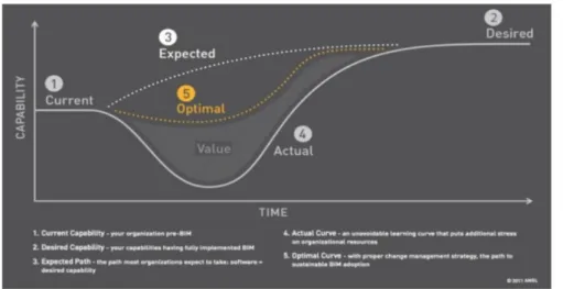
Figure 2.15 – Estimated learning curve of the AEC firms in BIM capabilities (ANGL, 2011). ... 18
Figure 2.16 – Individual BIM Competency – the Knowledge Skill Arrow (Succar, 2012). ... 20
Figure 2.17 – BIM maturity levels (Group, 2011). ... 20
Figure 2.18 – Traditional CAD collaborative process vs collaborative BIM process (Thomassen, 2011). ... 23
Figure 2.19 – The linear, iterative and integrated collaborative procedures, adapted (Löhnert et al., 2003). ... 24
Figure 2.20 – The decision making process in the integrated in the integrated collaborative procedure (Löhnert et al., 2003). ... 24
Figure 2.21 – Course of the progress in the integration and BIM collaborative implementation, adapted from (CRC, 2009, Succar, 2009a). ... 24
Figure 2.22 a), b) and c) – Project delivery agreements: Design-Bid-Build (DBB); Design-Build (DB); Integrated Project Delivery (IPD), respectively (Eastman et al., 2011, J.P. Cullen & Sons, 2008). ... 27
Figure 2.23 – Comparison between the Design-Bid-Build (DBB) and the Design-Build (DB) delivery-agreements (Eastman et al., 2008). ... 28
xvi University of Minho
Figure 2.25 – Data workflow integrated and iterative model (Thomassen, 2011). ... 33
Figure 2.26 – Macleamy curve, advantages in anticipating design decisions (Cavieres et al., 2011). .. 34
Figure 2.27 – Linked discipline models (Krygiel et al., 2010). ... 35
Figure 2.28 – Characteristics of local models, that constitute central disciple model (Krygiel et al., 2010). ... 35
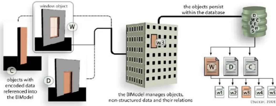
Figure 2.29 – BIM models and their objects – flow diagram (Succar, 2009a). ... 35
Figure 2.30 – Four stages of the Common Data Environment (CDE) (AEC-UK, 2012a). ... 36
Figure 2.31 a), b) and c) – Multi-discipline collaborative BIM working methods (Woddy, 2012). ... 37
Figure 2.32 – IFC platform (buildingSMART, 2013). ... 41
Figure 2.33 - Spatial structure of the data model. ... 41
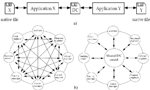
Figure 2.34 - Usage of the IFC data model: Format of exchange files (a) vs central IFC BIM model (b), adapted from (Nielson and Madsen, 2010, Chen et al., 2005). ... 42
Figure 2.35 – Functionality of the IFC platform (Zhang et al., 2012). ... 43
Figure 2.36 – IDM basic framework (Wix and Karlshøj, 2010). ... 44
Figure 2.37 – Procedure of accreditation of software in IFC (buildingSMART, 2013). ... 44
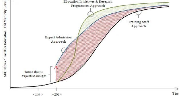
Figure 3.1 - BIM maturity curves – Training Staff Approach, Expert Admission Approach and Education Initiatives & Research Programme Approach, adapted from (Azenha et al., 2013b). ... 51
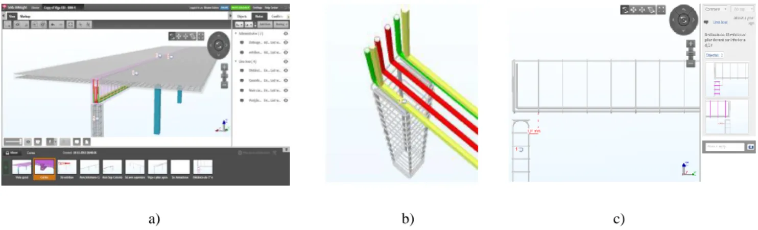
Figure 3.2 – Developed BIM model as a knowledge transmission tool for the curricular unit of Structural Concrete I (Lino et al., 2012): a) Dynamic view of the BIM model; b) View of the BIM model with coloured rebar; c) Commented notes highlighted in the BIM environment. ... 53
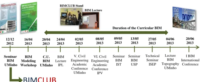
Figure 3.3 – Timeline of the events organized and/or participated by the BIM group of investigation at University of Minho. ... 54
Figure 3.4 a), b) and c) – Partial results of a statistical analysis about the subscribed participants of the BIM seminar 12/12/2012 held at the University of Minho. ... 55
Figure 3.5 a), b) and c) – Partial results of a statistical analysis about the members that are integrated in the BIMClub virtual community, elaborated on the 25/09/2013. ... 57
Figure 3.6 – Structural BIM model designed for the BIM modelling workshop in reinforced concrete structures. ... 60
Figure 3.7 – Partial results of a statistical analysis regarding the participants of the BIM modelling workshop in reinforced concrete structures. ... 60
Figure 3.8 – Subscribed student outline of the curricular unit “Building Information Modeling: Conception, Design and Construction” of 2012/2013 held at the University of Minho. ... 61
Figure 3.9 – Summary of the BIM models developed by the students of the curricular unit BIM held at University of Minho 2012/2013. ... 64
Figure 4.1 – BIM Execution Plan: Implementation Framework. ... 67
Figure 4.2 – Description of the components included in the BIM Overview Process Map. ... 77
Figure 4.3 – Graphical notation of each BIM Use present in the BIM Overview Process Map. ... 77
Figure 4.4 – BIM Overview Process Map (Level 1) – Collaborative process with all involved stakeholders with implementation of the Design-Bid-Build (DBB) contractual agreement, case study. ... 79
University of Minho xvii
Figure 4.5 – BIM Overview Process Map (Level 1) – Collaborative process with all involved
stakeholders with implementation of the Design-Build (DB) contractual agreement, case study. ... 80
Figure 4.6 – Description of the components included in the Detailed BIM Use Process Map. ... 82
Figure 4.7 – Description of the components employed in the sequencing of the Detailed BIM Use Process Map. ... 82
Figure 4.8 – BIM Overview Process Map (Level 1) – Collaborative process between the architect and structural engineer, case study... 85
Figure 4.9 – Detailed BIM Process Map (Level 2) – “Design Authoring” BIM use, case study... 89
Figure 4.10 – Detailed BIM Process Map (Level 2) – “Structural Analysis” BIM use, case study. ... 90
Figure 4.11 – Detailed BIM Process Map (Level 2) – “Site Analysis” BIM use, case study. ... 91
Figure 4.12 – Detailed BIM Process Map (Level 2) – “Cost Estimation” BIM use, case study. ... 92
Figure 4.13 – Detailed BIM Process Map (Level 2) – “Design Coordination” BIM use, case study. ... 93
Figure 4.14 – Detailed BIM Process Map (Level 2) – “Design Review” BIM use, case study. ... 94
Figure 4.15 – Detailed BIM Process Map (Level 2) – “Structural Erection” BIM use, case study. ... 95
Figure 4.16 a) e b) – Preliminary architectural model, case study (developed by CNLL, 2013)... 97
Figure 4.17 – Generation workflow of the structural BIM model from the architectural BIM model. . 98
Figure 4.18 – Identification of flawed building elements due to issues of interoperability. ... 99
Figure 4.19 – Final schematic design structural BIM model. ... 99
Figure 4.20 – Adjusted physical structural model for the structural analysis occurred in the schematic design phase. ... 100
Figure 4.21 – Analytical structural model for the structural analysis occurred in the schematic design phase. ... 100
Figure 4.22 – Architectural BIM Design Development Model - IFC Format (CNLL). ... 101
Figure 4.23 – Structural BIM Design Development Model - IFC Format. ... 101
Figure 4.24 - Preparation workflow of the design development structural BIM model to be exported to a structural analysis application. ... 102
Figure 4.25 – Vertical deformation analysis - (SLS + Post Tensioning) ... 103
Figure 4.26 – Required reinforcement area along the x-axis - (ULS). ... 103
Figure 4.27 – Design Detailed Structural BIM Model. ... 104
Figure 4.28 – Tracing of the post-tension tendons ... 104
Figure 4.29 – Footing reinforcement & detail of a metallic connection. ... 104
Figure 4.30 – Detailing of the post-tension tendons & voids of the slab. ... 104
Figure 4.31- Outline of the hollow slab & reinforcement of the structural concrete. ... 104
Figure 4.32 – Categorization of the information exchanges documented throughout the BIM Overview Process Map, with indication output/input information flows. ... 106
Figure 4.33 – Evolution of the average LOD attribution throughout the project phases regarding the repeated BIM uses in each phase. ... 110
Figure 4.34 – Evolution of the average LOD attribution throughout the project phases regarding the building elements clustered under the groups defined by the Talo 2000 system. ... 113
xviii University of Minho
Figure 4.35 – Evolution of the average LOD attribution of the shared structural objects between the
architectural and structural model. ... 113
Figure 4.36 – Compatibility in a central IFC model, between a shared architectural and structural BIM models with a high LODs attributions. ... 114
Figure 4.37 – BIM collaborative working method recommended for external firm use, BS119:2007, adapted (AEC-UK, 2012a). ... 116
Figure 4.38 – BIM collaborative working method recommended for internal firm use, adapted from (AEC-UK, 2012a). ... 116
Figure 4.39 – Localization of incongruities among the structural & architectural model (native format). ... 118
Figure 4.40 - Localization of incongruities among the structural & architectural model (central IFC model). ... 118
Figure 4.41 – BIM Collaboration Format (BCF) communication procedure. ... 119
Figure 4.42 – Recommended folder structure organization, adapted (AEC-UK, 2012a). ... 120
Figure 4.43 – Merging BIM model schema, case study. ... 121
Figure 4.44 – Core building elements and associated BIM modelling tool, case study. ... 123
Figure 4.45 – Material overlying due to required consistency of analytical model, case study. ... 125
Figure 4.46 – Singular situations of detailing that required manual modelling, case study. ... 125
Figure 4.47 – Quality assurance of the information take-off accuracy regarding the structural columns of the “design authoring” BIM use at the design development phase, case study. ... 127
Figure 4.48 – Analysis of the selected rulesets with indication of the degree of severity. ... 128
Figure A.I - Visual comparison of the LOD definition, accordingly to the LOD specification 2013 (BIMForum, 2013). ... 141
Figure A.II –Poster of the Seminar: “Building Information Modeling: Possibilities and challenges for the architecture and engineering sectors” (Sousa and Caires, 2013). ... 143
Figure A.III - Poster of the Workshop: “BIM Modeling in Reinforced Concrete Structures” (Silva, Sousa and Caires, 2013) ... 144
University of Minho xix
L
IST OF TABLES
Table 2.1 – Temporal relations among the main phases of the building´s lifecycle, with relation to the
BIM maturity stages and the contractual agreements, adapted from (Succar, 2009a). ... 30
Table 2.2 – Chronological placement of the BIM uses (CIC, 2008). ... 32
Table 2.3 – BIM use frequency and benefits with ranks (Kreider et al., 2008). ... 32
Table 2.4 – Main BIM Execution Plans initiatives. ... 48
Table 2.5 - Business Process Modeling Notation for BIM Process Maps (CIC, 2010). ... 50
Table 3.1 - Software selection by the groups and lecturing of the curricular unit BIM. ... 63
Table 4.1 – Recommended project information to document for future reference. ... 68
Table 4.2 – Projects Tasks & Goals, Case Study. ... 70
Table 4.3 – BIM Use selection worksheet, Case Study. ... 72
Table 4.4 – Chronological placement of the BIM uses, Case Study. ... 74
Table 4.5 – Project BIM uses deliverables & role matrix, Template. ... 75
Table 4.6 - Description of the BIM Information Exchange Requirements worksheet. ... 112
Table A.I – Main national BIM initiatives, according to the AIA in 2012. 142 Table A.II - Generic and specific requirements achieved the groups of the curricular unit BIM: Conception, Design and Construction, held at the University of Minho 2012/2013. ... 145
Table A.III – BIM software summary. ... 150
University of Minho xxi
L
IST OF SYMBOLS AND ABBREVIATIONS
2D Two-dimensional
3D Three-dimensional
AEC Architecture, Engineering and Construction
AEC/FM Architecture, Engineering, Construction and Facility Management AIA American Institute of Architects
APIs Application Programming Interfaces BCA Building and Construction Authority
BCF Building Collaboration Format
BEP BIM Execution Plan
BIM Building Information Modeling
BIM-FM BIM facility Management
BIT Building Information Technologies BPMN Business Process Modeling Notation
bSa buildingSMART alliance
CAD Computer-aided-design
CDE Common data environment
CIC Computer Integrated Construction CIS/2 CIMsteel Integration Standard Version 2
COBIM Common BIM Requirements
C.U. Curricular Unit
DB Design-Build
DBB Design-Bid-Build
ER(s) Exchange requirement(s)
FAUP Faculdade de Arquitetura da Universidade do Porto
FAUTL Faculdade de Arquitetura da Universidade Técnica de Lisboa FEUP Faculdade de Engenheira da Universidade do Porto
FPs Functional Parts
GC General Contractors
GUID Globally unique identifier
HVAC Heating ventilation and air conditioning IAI International Alliance for Interoperability ICTs Information and communication technologies IDM Information Delivery Manual
IE Information Exchanges
IFC Industry Foundation Classes
IFD International framework of dictionaries
IPD Integrated Project Delivery
xxii University of Minho
IPV Instituto Politécnico de Viana do Castelo ISO International Organization for Standardization IST Instituto Superior Técnico
LOD Level of Development
LNEC Laboratório Nacional de Engenharia Civil
OOP Object-oriented programming
MEP Mechanical, Electrical and Plumbing
MVDs Model View Definitions
NBIMS National BIM Standard – United States NIBS National Institute of Building Sciences PLM Product Lifecylce Management
PLPs Project lifecycle phases
PM(s) Process Map(s)
PTPC Plataforma Tecnológica Portuguesa da Construção
PPP Public Private Partnership
QTO Quantity Take-off
ROI Return on investment
RnD Research and development
SLS Service Limit State
UC Universidade de Coimbra
UK United Kingdom
UL Universidade Lusófona
ULS Ultimate Limit State
UMinho Universidade do Minho
US United States
USP Universidade de São Paulo
University of Minho 1
C
HAPTER
1
1 INTRODUCTION
1.1. Subject Background
Over the last decades, architecture, engineering and construction (AEC) industry has shown economical inefficiencies, when compared to other prime industries. During the last four decades, evolution analyses have shown that, even with technological progress, the AEC industry has presented a decrement, regarding the productivity index when compared to other industrial sectors, where their values have more than doubled (Martins, 2009, Eastman et al., 2011) (see figure 1.1). In fact, over many decades, this sector is the industrial activity that represents the largest consumption of material and human resources (Construction, 2009) (see figure 1.2). Furthermore, in most developed countries around the world, this sector embodies a vital slice of their economies (Macdonald, 2011), working as an important indicator of their economic performance.
Figure 1.1 – Construction Productivity Index vs Non-Farm Productivity Index, evaluated in the US
(NIBS, 2007).
Figure 1.2 – Evolution in the consumption of raw material resources (Wagner, 2002).
The information and communication technologies (ICTs) have modernized many sectors of the economy, being the primarily reason that justifies the growth of several industrial activities (Martins, 2009). The focal purposes of these technological tools are to optimize the transmission of information between stakeholders, enabling to nurture a consistent set of solutions that support a collaborative project (creation, management, dissemination and use of information) throughout the lifecycle of a certain project/process (Shen et al., 2009).
Studies have indicated that the main reason that differentiates the AEC industry from other sectors in growth (e.g. automotive and aviation), consists on the inaptitude of accepting and implementing advanced ICTs applications and consequently modernizing their work methods (Eastman et al., 2011). However, the optimization of the construction sector is a more complex procedure when compared to
2 University of Minho
other industries due to the elevated number of stakeholders that are involved and to the complexities associated in the development of building designs.
Fragmentation among the various stakeholders is appointed as the main insufficiency of the current construction industry (Isikdag and Underwood, 2010). Therefore, there has been a need to enhance the communication infrastructure, based on interoperable ICTs that facilitate information exchanges among the involved stakeholders and across the stages of the project lifecycle (Hammad et al., 2012). As a response to the increasing complexibility of the current projects and the disintegration between AEC stakeholders, ICTs have been developing at a very fast pace over the few years. The idea is to adapt triumphant technologies and methodologies that have been successfully implemented in other production industries in the AEC sector, namely the philosophies of lean and Product Lifecycle Management (PLM) (Martins, 2009). Economic efficiency, constructability, structural safety, performance, cost, sustainability, information interchange and effective team collaboration have been presented as key factors for construction productivity in the AEC industry (Lee et al., 2012, Ren et al., 2011).
In the recent years, a major shift in ICTs for the construction industry has been the proliferation of Building Information Modeling (BIM) as the new CAD paradigm (Bryde et al., 2012). BIM is one of the most promising developments in the AEC industry (Eastman et al., 2011), considered to be the new way of approaching the design, construction and maintenance of buildings (Azhar et al., 2009). In brief, BIM simulates the construction project in a virtual environment, by employing BIM ICTs, an accurate and integral 3D virtual model of the building, is digitally constructed and when completed these models contain all the necessary information in the form of data repository, which, consequently, supports the decision making of the stakeholders throughout the lifecycle of the project (Azhar, 2011, Gu and London, 2010).
Currently, there are already governments that have traced strategic implementation approaches to effectively introduce the BIM methodology under a collaborative environment for all projects in their countries, foreseeing the paramount impact of its applicability in the construction sector (Eastman et al., 2011). The uprising request of BIM allied with the current process of globalization of the construction sector have aroused the AEC firms to the inevitability of implementing BIM in their work procedures, to enhance their international competiveness. However, several constraints have been detected and contributed to the slower adoption of these new procedures (Lino et al., 2012, Construction, 2009). BIM represents a new paradigm shift within AEC industry, one that encourages integration of the roles of all stakeholders in a project (Azhar, 2011), where the lack of personnel with BIM competencies is a significant constraint retarding the implementation process (Sacks and Barak, 2010). Furthermore, although many standards relevant to BIM exist, it is suggested that there is an absence of implementation guidelines into which those standards could be incorporated for project teams to follow (Ahmad et al., 2012).
University of Minho 3
1.2. Dissertation’s scope and objectives
There is a consensus that more and more professionals of the AEC industry will need to acquire knowledge and skills to collaborate and cooperate through a BIM environment, which necessarily will include the curricular education developments, sanctioning the academic formation of BIM competencies to engineers/architects (Lino et al., 2012, Sacks and Barak, 2010). Equally important, is the development of implementation strategies, such as guides that enable the formulation of a BIM Execution Plan (BEP), which assimilate the current BIM standards and methodologies to help plan how to use BIM in collaborative projects. Acknowledging these needs, this thesis has the generic aim to contribute to the implementation of the BIM methodology among current and future stakeholders of the AEC industry, under a collaborative logic and embracing the latest developments and technologies in this field. Therefore, this work shall attend to three inter-related domains which are essential to foment a balanced implementation process, being described their objectives in following paragraphs.
The promotional initiatives of the BIM concept have the objective to announce and aware students (undergraduate/graduate), professors of civil engineering and architectural departments and even professionals of the construction sector, about the future challenges and trends of the AEC industry, explaining the importance of acquiring BIM competencies to match the proximate future requirements of the market. In some of these promotional initiatives it will be still intended to lecture the essential BIM concepts and demonstrate practical applications of this methodology. All promotional events presented in this dissertation had the contribution of the author and fall within the strategy assumed by the University of Minho, concerning the promotion of the BIM methodology among its students/teachers.
The second domain addresses the BIM curricular education initiatives, where the author of this thesis had the role of supporting the preparation and development of a curricular unit exclusively dedicated on BIM that was carried out at the University of Minho. The lecturing team was formed by professors and invited speakers that represented the diversified fields of the AEC industry with the aim to develop a comprehensive programme in order to convey the main concepts of BIM, to prepare the students with the necessary intellectual tools to be able to implement BIM in AEC projects, under a collaborative logic. Tacking advantage of Active Learning Methodologies it was intended that the students should develop a case study that matches the practical work that will be needed at a professional level.
The last domain and the core proposition of this MSc´s dissertation resides in the analysis of the collaborative BIM process. The main objective to achieve from this work consists in developing and presenting a set of methodologies that are capable to support and facilitate the implementation of a collaborative working procedure among the stakeholders of a project team to ensue throughout the project delivery, based on the BIM methodology and supported by interoperability. In parallel, it shall be performed a case study being analysed the practical application of the proposed implementation methodologies regarding the collaborative workflows that unfolds among the architect and structural engineer in a BIM project.
4 University of Minho
To be able to attain this core objective, a BIM Execution Plan (BEP) framework that incorporates the proposed implementation methodologies, intended to assist the Portuguese AEC firms on performing collaborative projects in a national/international scale will be developed. With this BEP framework the following topics shall be addressed:
- Process mapping procedure for planning the collaborative BIM workflows among the involved stakeholders during the phases of the project;
- Determination of the information exchange requirements and corresponding LOD classification attribution that occurs during the lifecycle of the project;
- BIM data management under a collaborative working procedure; - BIM model management;
- Quality assurance checks of the BIM models.
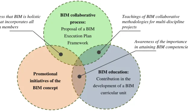
By culminating these three domains a series of interacting relations are awaited to surface (see figure 1.3), such as the recognition that BIM is a collaborative methodology that is holistic to all members and disciplines of a project, where it is imperative the acquisition of knowledge regarding the essential concepts of BIM to prepare the current and future stakeholders in performing multi-disciplined collaborative BIM projects.
Figure 1.3 – Three work domains outline of the present MSc dissertation.
It must be given relevance that the work developed in this dissertation was elaborated at the engineering office NEWTON – Consultores de Engenharia, Lda (NEWTON-C) were the application of the BIM methodology is already a reality. The partnership between the University of Minho and NEWTON-C and posteriorly the interviews/collaborative work held between NEWTON-C and Atelier Nuno Lacerda Lopes (CNLL) were core features that promoted the opportunity to develop this dissertation project granting a valuable scientific interest.
BIM collaborative process: Proposal of a BIM Execution Plan Framework Promotional initiatives of the BIM concept BIM education: Contribution in the development of a BIM curricular unit
Awareness of the importance in attaining BIM competencies Teachings of BIM collaborative methodologies for multi-discipline projects
Consciousness that BIM is holistic approach that incorporates all project team members
University of Minho 5
1.3. Chapter outline
This dissertation is organized in five chapters, the first of which consists of this introduction.
The literature review present in Chapter 2 embarks with the definition of the BIM concept and its potentialities, going onto aspects related to its implementation, where concretely the main barriers of implementation, possible strategies that can be undertaken to facilitate its adoption and the acknowledgment of the current worldwide status of BIM were nominated. In this literature review the description of the collaborative process in BIM is given great relevance, namely discussing its future trends, the current delivery contractual agreements and its relations with the BIM methodology. Furthermore, the data management characteristics that occur in a collaborative BIM working project, the interoperability aspects that are intrinsic in a BIM environment and brief description of the main BIM standards and construction classification systems generally applied in BIM specifications are delineated. To conclude, the most significant features that are commonly inherent in guides that formulate BIM Execution Plans are outlined.
Chapter 3 performs a summary of the promotional initiatives and the curricular unit of BIM that were carried out during the period of this dissertation work. For all initiatives that were held at the University of Minho, detailed information will be given about its description, objectives and tasks performed by the author. In addition, each initiative under study has a concluding point that analyses and discusses the acquired results.
Chapter 4 presents the proposed BIM Execution Plan (BEP) framework and concurrent analysis of the performed case study. This chapter commences by describing the investigation methodology followed to formulate the set of methodologies that are presented throughout the suggested implementation guide. During the chapter several fundamental issues regarding the planning strategy of a BIM collaborative working procedure are studied, being outlined a six stage method to strategize a detailed BIM Execution Plan for the involved stakeholders to follow during the project delivery. In each stage a theoretical explanation and the particular considerations admitted are indicated, followed by a practical exemplification through a case study that incorporates the collaborative project between the architect and structural engineer.
To conclude, Chapter 5 provides a summary of the main conclusions, together with some suggestions for possible extensions of the conducted work.
University of Minho 7
C
HAPTER
2
2. LITERATURE REVIEW
2.1. Building Information Modeling
2.1.1. The BIM concept
Building Information Modeling (BIM) is changing the construction industry (Barak et al., 2009), by embracing a 3D graphical representation to improve project members workflows, communications, collaborations and data exchanges.
BIM consists of a set of interacting policies, processes and technologies that generate a work methodology that is able to manage, the building design and project data, in a digital format throughout the building´s lifecycle (Succar, 2009a) (see figure 2.1). BIM resides on the virtual construction of a building in a 3D digital model, known as a building information model, were simultaneous simulations associated with design and construction can be automatically generated by architects, engineers and contractors giving them more support in developing more efficiently projects. BIM is able to provide a holistic and more interactive vision of the project, making explicit the interdependencies that prevail between the various project specialties of a building (architectural, structural, and mechanical, electrical and plumbing (MEP) layouts) by technologically coupling the involved stakeholder’s designs (Love et al., 2011) (see figure 2.2). Throughout the virtual construction of the digital model, the various stakeholders are constantly redefining and optimizing their discipline projects, hence updating the digital model under a collaborative logic (Carmona and Irwin, 2007).
Figure 2.1 – BIM present in the project lifecycle of a building (Mienr, 2012).
Figure 2.2 – Collaborative BIM methodology of sharing a virtual model, adapted (Musayelyan, 2009).
The definition of BIM has multiple understandings which are dependent on the value that the specific stakeholder wants to withdraw from this methodology. The contractor’s perspective of BIM can be put in terms of its technical aspects as a model or documentation tool, serving as a project instrument to
8 University of Minho
support the decision making and risk assessment throughout the construction and operation phase (Construction, 2009). Architects, structural engineers and MEP engineers who are more associated to the design phase, consider that BIM is an intelligent 3D virtual building model that can be constructed digitally by containing all aspects of the building information into an intelligent format that can be used to develop optimized building solutions with reduced risk and increased value before committing a design proposal (Barlish and Sullivan, 2012).
Summing up, the BIM concept essentially lays on a methodology of sharing information between all the stakeholders which is carried out during the lifecycle of the building, and materialized, by the use of specialized software, in the virtual construction of a 3D digital model (Lino et al., 2012). This 3D model in addition to containing the geometrical characteristics of the elements that constitute the building, it additionally clusters the properties and attributes of those building components, acknowledging the parametric relationships between those various elements (Lino et al., 2012).
2.1.1.1. The main fundamentals of BIM
BIM introduces a shift in the current work methodology undertaken in the construction sector, being transversal to all the actors involved, by changing the base documentation used in construction from one that is only readable by humans to new representations that are machine readable (Joeng et al., 2009). This innovated methodology enables a complete and accurate communication of engineering information without the need for detailed drawings (Sacks and Barak, 2010). BIM is fundamentally different from the traditional methodology (CAD), by being able to model the form, function and behaviour of the buildings components (Sacks et al., 2004). In the following paragraphs the main fundamentals related to the functionality of BIM shall be analysed.
Object-Oriented Modelling
The research and studies performed in computer-aided design (CAD) field can be grouped into two main lines of development. The traditional CAD that is highly known to the AEC sector is designated as entity-based CAD, which consists of a geometric representation that present any element by using points, lines and areas. The other line of development, and the one that is adopted by BIM, is entitled as object-based or object oriented CAD (Mattei, 2008), where the object-oriented modelling approach is adopted to represent project design.
The object-oriented modelling is based on the concepts of object-oriented programing (OOP). In simple terms, OOP is a type of programming where everything is coupled as self-sustainable “objects/elements” (Nirosh, 2011), where in the case of BIM consists in representing the building design by its elements (objects – footings, beams, columns, slabs, wall, among others) (see figure 2.3). It is perceptible the similarity between the real sequence of construction and the virtual construction that is performed in this manner of modelling, giving the stakeholders a better vision of the real construction. This form of modelling stands out from the traditional CAD, because each element is usually a digital representation of the physical and functional characteristics of an actual building
University of Minho 9
component to be used in a project (BCA, 2013f). Furthermore, each element has the ability to contain geometric (volume; shape; height; orientation; among others) and non-geometric (system data; performance data; mechanical characteristics; cost; among others) information.
Parametric 3D Digital Modelling and Parametric Relationships
Parametric 3D digital modelling consists on a modelling approach that is totally guided by parameters, based on algorithms that are pre-defined by the user (Azenha et al., 2013a). It is a technology in which all objects are using rules and parameters that define its geometry and behaviour, as well as some non-geometric features and properties (Henriques, 2012). Hence, all the geometry can be controlled by a small number of key parameters (Azenha et al., 2013a). In figure 2.4 a practical example of parametric modelling is shown, in which an application named Grasshoper3D, defined as a graphical algorithm editor was applied, enables to control the behaviour of the form by selecting key parameters. In this case it is illustrated the integration of the parametric model with a structural analysis software, with the intent to optimize the structural design.
Figure 2.4 – Structural analysis extraction from Grasshopper3D (Mirtschin, 2012).
Figure 2.5 - Parametric relationships between beam and column, adapted (Sacks et al., 2004).
A key characteristic considered in parametric models is the ability to define the interactions between the elements incorporated in a model. The parametric relationships are defined by a series of rule sets
Figure 2.3 – Object-oriented modelling, adapted from (NEWTON, 2012).
Slab Footing Beam Column Wall BIM model Graphical algorithm editor Parametric Model Structural Analysis
10 University of Minho
that characterize the connecting relations among the building components (see figure 2.5), defining the possible constraints and implications between the respective objects (FEUP, 2011). These parametric relations are a core characteristic of BIM models being responsible for many of its key features. However, the definition between objects is also one of the biggest challenges for BIM software producers since there are numerous forms for two or more elements to relate to each other (Ferraz and Morais, 2012).
Information Model
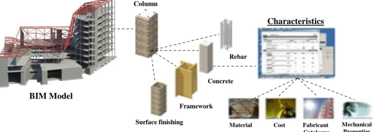
The usage of parametric object-oriented modelling enables the creation of elements “rich” in data and, consequently, the resulting virtual model can be defined as a 3D model of digital information. In other words, the building model is a repository of information which is developed and maturated by the involved stakeholders throughout the lifecycle of a building. The way on how a BIM model organizes and displays its data, in terms of software engineering is called a data model structure (FEUP, 2011). For a better understanding, figure 2.6 illustrates the data model structure regarding a column, demonstrating how the information relating to that component could be organized.
Another key advantage of OOP when relating to BIM, is the ability of programmers to create “modules” within an information model that do not need to be altered when adding new types of objects (Lewis and Loftus, 2008, Shen et al., 2009). Users can simply create a new component of a building that inherits many of its features from existing similar objects. This introduces the concepts of “classes” or “parametric families” and “heritage” between classes which are essential aspects of the data management of a BIM model. In BIM models all the objects are organized according to different levels of classes. For an example, if the user wants to create a “metallic HEB 300 column”, this BIM object will be part of the following classes: initiating by its superclass “columns”, then “metallic columns”, following “metallic HEB columns”, and finally the class “metallic HEB 300 columns” is included. Only when applying the “final class” in a BIM model does it become a BIM object.
BIM Model
Surface finishing
Rebar
Characteristics
Material Cost Fabricant Catalogue Mechanical Properties Column Framework Concrete
Figure 2.6 – Organization of the information in the BIM model, adapted from (Autodesk, 2011, Meireles, 2009).
University of Minho 11
Interoperability
As mentioned throughout the above topics, information and its management in the BIM models are key aspects of the BIM methodology. The ability to communicate, re-use and share data, efficiently, without loss or misinterpretation between stakeholders that use different software applications is an essential requirement that needs to be matched (AEC-UK, 2012a), in order to integrate the collaborative procedures with the technologies that are inherent to the BIM concept.
Interoperability in a BIM context can be defined as the capability of transmitting data between applications, as well as the ability of multiple applications working together (Eastman et al., 2011). The software applications used in BIM can be grouped as BIM tools or BIM platforms. A BIM tool can be defined as task-specific application that produces a specific outcome (Eastman et al., 2011). For example, tools can generate cost estimation, clash detection, structural analysis, energy analysis, renderings, among other uses. A BIM platform is an application that generates data for multiple uses (Eastman et al., 2011), allowing the creation and editing of the information relevant to the BIM model, containing the definition of classes and parametric relationships (Azenha et al., 2013a). Most BIM platforms, also internally, incorporate tool functionality such as drawing production and clash detection (Eastman et al., 2011).
In BIM, interoperability can be completed in multiple levels (Azenha et al., 2013a): - Interoperability between a BIM platform and a BIM tool;
- Interoperability between a BIM tool and a BIM tool;
- Interoperability between a BIM platform and a BIM platform.
In these three levels the interoperability between the various applications can be obtained through a direct or an indirect link. The direct link is defined as a singular connection between two software applications, e.g. via an Application Programming Interface (API). The API is an interface implemented by a software application that enables the interaction with other applications (tools/platforms) (Eastman et al., 2011, Nielson and Madsen, 2010). On the other hand, the indirect link consist on using information exchange standards like the Industry Foundation Classes (IFC) – for building planning, design, construction and management, or CIMsteel Integration Standard Version 2 (CIS/2) – for structural steel engineering and fabrication (Eastman et al., 2011), among other data exchange standards.
Abstractions
Abstractions in the BIM methodology are a concept that is associated with the management of the information when modelling. Generally, an abstraction corresponds to a vision of a reality where it is supressed a set of information that are considered unnecessary for the purpose in mind (Martins, 2009).
The concept of abstraction in BIM models are directly related to the sharing of information, where the abstractions can be defined as high or low (Esteves, 2012). When assisting to a high level of abstraction the sharing of information is censured generally only presenting the object. On the contrary, when there is low or no abstractions involved, a complete sharing of information is
12 University of Minho
conceived. As a result, the abstraction considered will have an effect on the modelling detail (geometrical and non-geometrical) of the objects during the collaborative process.
The level of abstraction considered by the stakeholders during the collaborative BIM process can be used to consider possible restrictions on collaboration, namely to protect the intellectual property of the actors of the project team. These intellectual properties can be exemplified as libraries of objects that are developed by companies.
2.1.1.2. Features and potentialities
BIM is currently capturing the interest of the AEC industry due to the innovated potentialities and diverse applications that can be applied during the phases of the project (Love et al., 2011, Azhar, 2011, Bryde et al., 2012). The subsequent points, present the main features (general and specific) of BIM that are commonly applied in practical cases, according to the literature review (Kim, 2011, Azhar, 2011, FEUP, 2011).
General Features
The following general features are transversal to all the specialities that are involved in a construction project. In brief, these general features are:
- Rapid visualization of the 3D model and the information of the project; - Automatic generation of the technical documents;
- Automatic Quantity Take-off (QTO);
- Data sharing and coordination between the involved stakeholders.
The rapid visualization of the BIM model is the simplest feature of its technology, enabling an enhanced visual comprehension by the stakeholders throughout the lifecycle of the building (Joeng et al., 2009). Visualization helps to make the process management more transparent. In other words, the 3D BIM model can easily be manually inspected to verify what has been and has not been included in a given area or discipline of a project (Hammad et al., 2012). Furthermore, as the objects that constitute the BIM model are parametrically relatable, it enables the user to determine, freely, the view to be automatically generated (plans views, section views, elevation views, 3D views and construction details) (see figure 2.7).
Figure 2.7 – Automatic production of views generated in a BIM model (Azenha et al., 2013a). BIM Model
Plan 3D View – Interior
University of Minho 13
As recognized, the production of technical documents is one of the most arduous activities of the construction industry, both in terms of design documentation for licensing, procurement or construction documents (Monteiro and Martins, 2011). In the traditional methodology, whenever it is needed to be performed a design change it would imply extending all the alterations to the design documents associated to the specific views that are involved. When using BIM, the process of technical document production is automatized, implying that any modification to the project will be automatically verified in all the types of documentation that are involved (drawings and/or schedule documentation, for instance quantity take-off (QTO)) (Eastman et al., 2011). This potentiality is considered to be one of the main features of BIM (Fontes et al., 2010), because it allows all the stakeholders to remain updated to all the changes that occur in the shared model, being essential to achieve an efficient collaborative process.
Another general feature consists on the elaboration of a QTO schedule, which is considered to be one of the most time fulfilling and responsible activities in the construction sector (Eastman et al., 2011). As already mentioned parametric object-oriented modelling requires the specification of parameters regarding each object. With those parameters, namely the geometric (length, height, thickness) it is possible to retrieve from the model, instantaneously and automatically the quantification of each element that composes the building, attaining the bill of quantities (Eastman et al., 2011, Fontes et al., 2010). The QTO tool enables each stakeholder to test various solutions, rapidly, and support the decision making during the lifecycle of the building.
The sharing of data through the models of the involved stakeholders of a project, enables the work to be elaborated from the same data environment, which reduces possible errors and omissions when exchanging information documents (BCA, 2013f).
Another two key aspects consist on the accessibility to the project´s information and the ability to perform the compatibility checks between the disciplines that are involved. The coordination between the various stakeholder´s models enable to verify the possible conflict detections that occur between each discipline and indirectly assist on the evaluation of possible alternative solutions (Eastman et al., 2011). It should be noted that, the interference checking is customarily elaborated by the architect, but with BIM it is recommended to be performed occasionally by each actor of the project, granting more quality to the project design procedure (BCA, 2013f, AEC-UK, 2012a, COBIM, 2012c).
Architectural BIM features
The main potentialities that can be delivered from BIM applications for an architect are (BCA, 2013a, Eastman et al., 2011):
- Mass Modelling enables the architect to study possible forms of the building´s architecture considering the landscape integration and initial QTO analyses. It should be noted that, mass modelling is only suggested to be considered in the initial phases of the architectural design; - Sun studies are a significant benefit to determine the orientation, location and functional
14 University of Minho
- Automatic integration with energy analysis applications; - Animated 3D visualization and renderings (see figure 2.9);
- Production of detailed design layouts and detailed drawings (see figure 2.10);
- Automatic spatial validation, analysing automatically whether the architectural design is in conformance with the spatial program requirements (GSA, 2007).
Figure 2.8 – Architecture BIM features: Sun study (Simmons, 2011).
Figure 2.9 – Architecture BIM features: Renderings (Fonseca et al., 2013).
Figure 2.10 – Architecture BIM features: Production of detailed 2D drawings, adapted (AEC-UK, 2012a).
Structural Engineer BIM features
The main potentialities that can be delivered from BIM applications for a structural engineer are (Joeng et al., 2009, BCA, 2013c, Nielson and Madsen, 2010):
- Automatic calculation of the earthworks – excavations and landfills; - Automatic integration with structural analysis applications;
- Structural erection (sequential planning – 4D BIM);
- Structural detailing with respective QTO analysis – reinforcement concrete (see figure 2.11); steel connections; among others;
- Structural shop drawings (see figure 2.12);
- Automatic verifications of structural regulations and standards; - Structural monitoring (Ferreira, 2011);
BIM Model 2D Information contained within the model
University of Minho 15
- Integration with the fabrication and construction phases.
Figure 2.11 – Structural reinforcement detailing with production of 2D detailed drawings (Lee et al., 2012).
Figure 2.12 – Structural steel connections – shop drawings (BCA, 2013c).
MEP Engineer BIM features
For MEP engineers the main features to retrieve from BIM applications can be, briefly, listed as (Eastman et al., 2011, BCA, 2013e):
- Class detection between the various systems involved in a MEP engineers workflow (Heating, ventilation and air conditioning (HVAC); water supply and sanitary plumbing; electrical circuits and mechanical equipment) (see figure 2.13);
- Detailed drawings – shop drawings;
- Automatic design and tracing – By entering the parameters that define each equipment/object of a certain system of the building (e.g. the exit flow rate of lavatory), a MEP BIM application is capable to determine automatically the sizing of the diverse pipes or ducts that constitute the system and present a set of alternative layouts intended to be the most economic;