A Complete Internet of Things Solution for
Real-Time Web Monitoring
Pedro de Barbosa Mendonça Diogo
4
A Com
ple
te Inter
ne
t of Things Solution for R
eal-T
ime W
Dissertação de Mestrado
Ciclo de Estudos Integrados Conducentes ao
Grau de Mestre em Engenharia de Comunicações
Trabalho efetuado sob a orientação do
Professor Doutor Nuno Vasco Lopes
Professor Doutor Luis Paulo Reis
A Complete Internet of Things Solution for
Real-Time Web Monitoring
Therefore, this dissertation presents the related work done in this field, the typical current IoT systems described in the literature, and how such a system can be deployed using state-of-the-art open-source tools compliant to the most relevant standards. The developed system breaks down the current paradigm of vertical solutions, by adopting latest standards and protocols specifically designed for IoT. To demonstrate what kind of solutions can be build using this system architecture, a real-time fitness web monitoring testbed was set. The solution is composed of a low-cost node reporting, in real-time, the monitored heart rate to a Web page, while also possessing the ability to share this data with any other interested entity. To demonstrate the potential of IoT and how the adoption of proper standards and adequate protocols allow for the development of complex and richer applications, a complete solution was designed. With this solution, it was possible to demonstrate how one can share the sensed data, in a standardized way, to other potential interested parties (doctors or nursing facilities, for instance) and how such standardized architectures can be tweaked to meet specific requirements for special scenarios, like the real-time web monitoring here developed. To validate this solution, an experiment was set up, demonstrating that there is, indeed, a need to use adequate protocols for this type of monitoring.
Ultimately, this work showcases what kind of impact the IoT will have in the health-sector, breaking the current paradigm of silo solutions, making way for new, smarter, scalable and interoperable solutions, when adopting this technology in a proper way.
e serviços a nível de rede (cloud) em diferentes sectores como, por exemplo, saúde, logísticas e aplicações domésticas, uma
arquitetura apenas pode não ser a mais indicada para todas as soluções.
Neste sentido, esta dissertação apresenta, inicialmente, o trabalho relacionado nesta área, os tipos de sistemas que são naturalmente encontrados na literatura, e quais os problemas presentes nestas soluções auto-apelidadas de Internet das Coisas. Como forma de solução, é apresentado como estes podem agora ser desenvolvidos, usando as mais recentes normas e arquiteturas, bem como as ferramentas grátis e de código aberto que são compatíveis com essas mesmas normas. Seguindo esta lógica, é apresentado o sistema desenvolvido que, de uma forma geral, quebra o paradigma atual de criação de soluções verticais, adotando as mesmas normas e protocolos mencionados anteriormente, e que foram concebidos especificamente para a Internet das Coisas. Tendo em conta que esta tecnologia terá um grande impacto na área da saúde, foi desenvolvida uma aplicação de teste. O sistema é composto por um nó, de baixo custo, que monitoriza o batimento cardíaco e envia os dados para uma entidade que os disponibiliza, tanto em tempo real, via Web, como a quaisquer outras entidades que estejam interessadas nestes dados. Esta solução tem como objetivo demonstrar o potencial máximo que está inerente à Internet das Coisas: soluções mais ubíquas, abertas e escaláveis que, conjuntamente, possibilitam a criação de serviços e aplicações mais ricas e inteligentes. Visto que a solução desenvolvida tem que ser capaz de oferecer uma monitorização Web em tempo-real dos dados recolhidos, foi desenvolvido um mecanismo especifico e mais adequado para a aplicação em causa. Ainda, tendo em conta que o conjunto de protocolos utilizados não estão incorporados na norma adotada para o sistema Internet das Coisas, foi feita uma experiência onde é demonstrada a necessidade destas normas incorporarem protocolos adequados para as diferentes soluções tipicamente encontradas em sistemas que recorrem a esta tecnologia.
1 Introduction 1
1.1 Motivation . . . 1
1.2 Objectives . . . 1
1.3 Document Structure . . . 2
2 IoT Technology and Protocols 3 2.1 Physical, Data and Network layers . . . 4
2.1.1 IEEE 802.15.4 . . . 4
2.1.2 6LoWPAN . . . 4
2.2 Transport and Application layers . . . 6
2.2.1 CoAP . . . 7
2.2.2 MQTT . . . 15
3.1.1 Architecture . . . 22
3.1.2 OneM2M . . . 25
3.2 OMA Lightweight M2M . . . 28
3.2.1 Overall High Level Functionalities . . . 28
3.2.2 Architecture . . . 28
3.2.3 Object Model . . . 30
3.3 IoT Reference Model and Guidelines . . . 31
3.3.1 IoT-A . . . 31
3.3.2 IPSO Alliance . . . 33
3.4 Comparison . . . 34
3.5 Literature Review . . . 35
3.6 Conclusion . . . 40
4 IoT Solution for Real Time Fitness Web Monitoring 43 4.1 System Architecture . . . 43
4.2 Testbed Solution . . . 49
4.3 Solution Overview . . . 50
4.4 Strengths . . . 52
4.5 Conclusion . . . 56
5 System Implementation, Configuration and Validation 59 5.1 Implementation Overview . . . 59
6 Conclusion and Future Work 87
2.5 HTTP-CoAP proxying mechanism. [27] . . . 10
2.6 CoAP - Proxying and caching. [27] . . . 11
2.7 First interaction with an HTTP-CoAP proxy - listing CoAP resources to test. . . 11
2.8 Second interaction with an HTTP-CoAP proxy - GET request. . . 12
2.9 Final interaction with an HTTP-CoAP proxy - response of previous GET request. . . 13
2.10 CoAP’s Observation feature example [29] . . . 14
2.11 MQTT: Pub/Sub protocol[34] . . . 15
2.12 MQTT’s wildcard support example . . . 16
2.13 MQTT-SN Architecture [34] . . . 18
3.1 ETSI’s M2M High Level System Architecture [44] . . . 23
3.2 SCL’s standardized resource structure tree[45] . . . 24
3.3 Simple use of SCL resources to exchange data (adapted from [48]) . . . 25
3.9 IoT Architectural Reference Model building blocks . . . 32
3.10 Representation of the System Architecture defined in [72] . . . 36
3.11 Architecture overview of [76] . . . 37
3.12 Monitoring system architecture of [79] . . . 39
3.13 Simplified data flow of [79] . . . 39
4.1 IoT System Architecture Proposal . . . 44
4.2 Current M2M/IoT Silos . . . 45
4.3 IoT System Architecture Proposal - Trusted Applications . . . 47
4.4 IoT System Architecture Proposal - Mobility . . . 48
4.5 Solution’s Architecture . . . 51
4.6 Solution´s Protocol Stack . . . 51
4.7 Solution’s architecture after ETSI M2M adoption. . . 53
4.8 Node.js’s event loop [93] . . . 55
5.1 Raspberry Pi’s software modules overview . . . 60
5.2 6lbr’s Smart Bridge operation mode [114] . . . 66
5.3 Gateway Interworking Proxy (GIP) Fluxogram . . . 68
5.4 Arduino - GIP Registration . . . 69
5.5 GIP - Update a new Application’s Content Instance . . . 70
5.6 Real-Time Monitoring via Web Sockets . . . 72
5.15 GIP registering new application and updating content . . . 80
5.16 Applications registered at GSCL . . . 81
5.17 Delay difference between MQTT and standard ETSI M2M subscription mechanism . . . 83
ARM Architectural Reference Model BLE Bluetooth Low Energy BPM Beats per Minute
CoAP Constrained Application Protocol CRUD Create, Update, Retrieve and Delete CSEs Common Services Entities CSF Common Services Functions DA Device Application
DAD Duplicate Address Detection DIP Device Interworking Proxy DNS Domain Name System
GPRS General Packet Radio Service GSCL Gateway Service Capability Layer
IEEE Institute of Electrical and Electronics Engineers IETF Internet Engineering Task Force
IoT Internet of Things
IoT-A Internet of Things Architecture IP Internet Protocol
iPSO Internet Protocol for Smart Objects Alliance ISPs Internet Service Providers
LWM2M Lightweight M2M M2M Machine to Machine MAC Media Access Control
MQTT Message Queue Telemetry Transport NA Network Application
NACK Negative-Acknowledge NAT Network Address Translation ND Neighbor Discover
NIP Network Interworking Proxy NSCL Network Service Capability Layer
RA Router Advertisement RIO Route Information Option
ROLL Routing over Low Power and Lossy Networks RPL Ripple
RS Router Solicitation
SAA Stateless Address Auto-Configuration SCL Service Capability Layer
SDO Standards Development Organization SOTA State-of-the-Art
SSL Secure Sockets Layer TCP Transmission Control Protocol TLS Transport Layer Security
UART Universal Asynchronous Receiver/Transmitter UDP User Datagram Protocol
URI Uniform Resource Identifier VPN Virtual Private Network VPS Virtual Private Server
There is no denying that the Internet of Things is evolving and it will generate billions of dollars in the upcoming years. Gartner, the world’s leading information technology research and advisory company, said, in December 2013, that the IoT will grow to 26 billion units in 2020, resulting in 1.9$ trillion in global economic value-add through sales into diverse end markets [1]. Similarly, Cisco said that it will create, from 2013 to 2022, a 14.4$ Trillion of value at stake for companies and industry [2]. Since we are talking about connecting everything to the Internet, there is an unimaginable amount of business opportunities involved. Sectors like industry, logistics and health are a few of the major ones embracing IoT.
Currently, IoT suffers from fragmentation, interoperability and scalability issues. There are protocols and standards defined specifically for IoT, but they are not being adopted by every IoT system designer, which leads to, to put it simply, interoperability issues. For IoT to grow to its full potential, there is yet work to be done in this field. Currently, there are standards developed by, for instance, IETF, OMA and ETSI that will help overcome this issue, but it is still a work in progress, and its wide adoption is still uncertain. IoT is not just about connecting things to the internet - it is expected for those things and other complex services to work together, for a specific end, autonomically.
1.2 Objectives
This Masters Thesis’ main goals are to demonstrate the most problematic issues around M2M and IoT systems/applications and how they can be avoided using latest architectural standards and protocols specifically tailored for IoT. This will
demon-words, how different IoT Systems could interoperate and make way for smarter applications that provide, ultimately, better quality of live. The work also takes into account the cost of such system (as low cost as possible), openness (use of open and free source code only) and the incorporation of tools that are compliant to current and/or future final versions of the specifications developed by entities such as ETSI. This last case offers future-proof capabilities to the developed system.
1.3 Document Structure
In order to achieve the aforementioned claims, the document is structured in a way to ease the understanding of such objectives. Chapter 2 starts by introducing the most common technology and protocols present in typical IoT Systems, ranging from the physical layer up to the application layer. It is important to understand the complexity of such protocols and the resulting proliferation of work in this field, due to the technology’s inherent complexity. For the IoT to work, proper protocols must be defined at each layer to seamlessly work together, as one IoT System is not simply composed of one protocol from one layer only. Continuing the same line of thought, chapter 3 introduces the most recent IoT/M2M architectural standards and guidelines which are much needed for correctly designing a real IoT System. This is still a work in progress, but the chapter already mentions the most promising ones and those which are already finalized. They form the first step to achieve a more robust Internet of Things. After this state-of-the-art analysis, the same chapter showcases the typical IoT Systems found in the literature, illustrating how the commonly found bad IoT System designing practices restricts its potential to fully grow to the desired level. Taking all this into account, Chapter 4 details what is the ideal Internet of Things and how such a thing can be achieved. It starts by introducing an high-level view of the desired Internet of Things and how it can be developed using the state-of-the-art architectural standards and protocols presented in chapter 2 and 3; with this previously mentioned guidelines, it is next detailed the implemented system and how it will make use of these state-of-the-art standards and protocols to operate in compliance to what was previously described as the desired IoT. Finally, chapter 5 details the implementation of such solution: which hardware and software was used and how it all works together as a complete IoT System. The last chapter concludes with an analysis of the whole work and how the solution could be improved, at hardware and software level, to get as close as possible to the previously mentioned desired IoT System
and only itself, is then connected to the internet. There is no real end-to-end connectivity between the different nodes and the internet, as they do not support any means to communicate with the Internet world. In general, these systems possess limitations in terms of interconnectivity, reachability, and scalability.
However, major entities such as IETF and IEEE acknowledged this problem and started to work on standards and protocols specifically designed for IoT solutions. With their efforts, it is now possible for nodes to be directly connected to the internet while providing device management capabilities, standard interfaces for M2M and direct communication with regular web services and applications. All of this combined solves most of the common problems with present solutions: reachability, interoperability, scalability and security. The following sections will detail the on going efforts of different Organizations, Alliances and Task Forces on building protocols and standards to support IoT and M2M solutions.
When deploying an IoT application, one protocol is usually chosen, given the fact that some have advantages over others. However, they are chosen accordingly to the specific application in mind and parameters like messaging pattern, network capabilities, security, etc.). Most of the systems usually use either CoAP, MQTT, MQTT-SN or XMPP as protocols for ap-plication data, as Cisco acknowledges [4], and, as an example, they are already being used by commercially successful applications like Skynet [5], Pinoccio [6] and mbed (former Sensinode) [7]. At a networking level, 6LoWPAN [8], RPL [9], and ZigBee IP are the most widely used in commercial applications (Thingsquare [10], for example) and in the literature itself, as the next sections denotes. Besides these protocols and standards, there are also relevant and much needed frameworks and architectures combining all entities and services present in typical IoT and M2M systems to provide interoperability all
2.1 Physical, Data and Network layers
2.1.1 IEEE 802.15.4
IEEE 802.15.4 [11] is a standard which defines low power wireless embedded radio communications at 2.4 GHz (Global) and sub-GHz: 915 MHz (North America) and 868 MHz (Europe). 915 MHz and 2.4 GHz frequency bands are internationally unlicensed ones (ISM - Industrial, Scientific and Medical radio bands), while 868 MHz is defined for non-specific short range devices. As a result of this frequency difference, variable data rates of 20, 40 and 250 Kbps are possible to achieve. It was designed to be used in lossy and low power networks (LLN) where nodes must sleep most of the time to achieve multi month or multi year battery life. These typical constrained network often present unstable radio environment and the physical layer packet size is very limited (~100 bytes) [12]. IEEE 802.15.4’s physical payload size has a maximum of 127 bytes, with 72-116 bytes of actual size after framing, addressing and optional security (128-bit AES encryption) at link layer.
2.1.2 6LoWPAN
IETF’s Working Group 6LoWPAN started to develop, in 2005, a solution to bring IPv6 to IEEE 802.15.4. Two years after, in 2007, two initial RFCs (RFC 4919 and RFC 4944) were approved stating the problem [13] and specifying the format [14]. However, these two were later updated by RFC 6282 [15] and RFC 6775 [8] which state the two main functions of 6LoWPAN: compression format for IPv6 Datagrams over different IEEE 802.15.4-based networks (6LoWPAN was, initially, designed for 802.15.4 and its specific features [16]) and neighbor discovery optimization.
This standard adaptation layer allows small low power devices to connect to the whole Internet, providing interoperability between low power devices and existing IP devices. As IPv4 addresses are becoming scarce, IPv6 was the natural way to go. With it, current small islands of wireless devices can be transformed into stub networks of the Internet where IP packets can be sent from or destined to. When bringing IPv6 connectivity to such devices, criteria like limited energy power, resources and lossy links had to be kept in mind. 6LowPAN WG decided to work on IPv6 standard and leverage existing standards, rather than creating something completely new, thus, enabling the use of standard socket API (UDP), ICMP, and
Figure 2.1: A 6LoWPAN example [16]
direct end-to-end IPv6 routing, which, in turn, allows for a better integration with the whole Internet and the development of new applications.
One of the major problems the Working Group encountered, was related to IPv6 typical frame size. IPv6 MTU alone is 1280 bytes long which mean that some times, a frame of around 400 or 500 bytes will have to be fragmented to fit in 802.15.4’s 127 byte frame. Fragmentation, albeit not very efficient, was made possible to allow backward compatibility with the rest of the Internet. Also, because of this 127 byte frame limitation, compression must be done. With IEEE 802.15.4 MAC header (up to 25 bytes with no security, or 46 bytes with AES-128), 6LoWPAN has roughly only 100 bytes available to work with; and if IPv6 (40 bytes) and UDP (8 bytes) headers were used in there, the resulting payload space would be 53 bytes only. 6LoWPAN header compression transforms these 48 bytes down to just 6 bytes, in its best scenario, and to about 11-12 bytes in worst case scenario [17]. With this compression, the payload is now 108 bytes long, which is enough for IoT protocols like CoAP, MQTT-SN, RTP or custom UDP protocols. As 6LoWPAN was designed for typical Wireless Sensor Networks, mesh routing is also supported.
IP addressing in 6LoWPAN is very identical to any IPv6 network. They are automatically formed from LoWPAN’s prefix and link-layer address of the wireless interface (EUI-64). A typical 128 bytes IPv6 address is composed of a 64 bytes prefix and a 64 bytes interface identification (IID). In 6LoWPAN the IID part of the IPv6 address is generated trough the link-layer address of the wireless interface and the prefix is obtained from Neighbor Discovery’s (ND) Router Advertiser (RA) messages as in a typical IPv6 network. The use of link-layer EUI-64 allows for what is called a Stateless Address Configuration. This known
RPL
IETF has also defined a routing protocol for this kind of network and is called RPL (Ripple), which is detailed next. Forwarding and Routing can be performed at different layers: Layer 2 (“Mesh-Under”) and Layer 3 (“Route-Over”). Since IP routing is domain-centric, 6LoWPAN can adopt one routing algorithm while the domain above the Edge Router adopts its own. IPv6 and routing are different things, meaning that IPv6 is open to any algorithm. Route-Over means that IP routing always involves IP layer as noted in Figure 2.2. IETF has created a working group called ROLL (Routing over Low Power and Lossy Networks)[18] to design a new routing algorithm that takes these network characteristics in mind. Knowing that this algorithm would be used in M2M typical communications where data flows in a standard way (from nodes to the internet, and vice-versa), they have designed RPL [9]. RPL algorithm has a Proactive distance-vector approach. It is proactive because it creates a routing table before it is actually needed. With RPL each host only knows how to route to the Router above, which, in turn, knows how to route to the Edge Router; similarly, and following M2M typical data flow, the Edge Router knows only how to route in an downstream way. In these type of LoWPANs there is no need to maintain routing information about everything and everyone and that is why it is so efficient. Also important about it is that it supports duplicable backup routes - this means that if one host can not communicate to one of its linked Routers (Router’s failure, or any other reason), it can use the backup link to route the data to another Router. This actually happens in real time and is much needed when the LoWPAN has more than one Edge Router (which is possible, to extend its range, just like in WiFi) [16].
Mesh-under happens at Layer 2 and is actually invisible to 6LowPAN. This means that it uses 64-bit EUI-64 or 16 bits short address from Link Layer.
2.2 Transport and Application layers
With 6LoWPAN layer, efficient routing algorithm and the RF technology to transmit data, all that is missing now is a proper transport and application protocol to be used in IoT. At the transport layer, TCP is not commonly used in these low power and lossy networks due to its complexity and lack of efficient dealing of wireless loss and packet error rate; for this matter, UDP is the de-facto transport protocol used with 6LoWPAN. At the application layer, there are several options. Given the fact that
Figure 2.2: 6LoWPAN routing model “Route-Over” [16]
TCP should be avoid, the most efficient ones currently being used in a constrained device are the ones who support UDP, like: RTP, SIP, MQTT-SN, SNMP and CoAP, being the last three the most widely employed [16]. HTTP and FTP are too heavy for these devices and networks. The main UDP-based protocols are analyzed further and, to summarize, a comparison chart is presented, between those that are more IoT-oriented.
2.2.1 CoAP
CoAP (Constrained Application Protocol [19]) was developed by IETF Working Group called CoRE (Constrained RESTful Environments [20]) as an answer to the lack of Web Services capabilities present in this constrained environment. With CoAP, it is possible to embed a Web Service on small low power devices, enabling interaction with the whole Web due to its REST-architecture nature, resource discovery mechanism and HTTP binding. It is a simple protocol that implements HTTP’s REST model, in a small 4-byte header, while avoiding most of its complex features. Furthermore, it was designed having sleeping nodes in mind, providing security, thanks to DTLS, multicast support, built-in resource discovery, reliability, and a new observe feature. REST model, enabling a notification architecture [21]. This is a very important protocol as it enables a many-to-many communication paradigm, via interaction with other services available on the web. Although it is often used with UDP as the underlying protocol, it is also possible to bind to SMS or TCP. This makes it easy to adopt Device Managing capabilities over cellular network like OMA’s Lightweight M2M protocol [22], or LWM2M, which is also here analyzed.
Methods, Transactions messages and URI
Just like HTTP, GET, POST, PUT and DELETE methods are also present in CoAP. Fig2.3 represents the message format. The Code field can represent methods (GET=1, POST=2, PUT=3, DELETE=4) or response codes, which are a subset of adapted
Figure 2.3: [19] CoAP Message Format HTTP status codes and CoAP-specific.
It is possible to have synchronous messaging, when using Confirmable messages (“T = 0” field - Transaction messages). When sending confirmable requests, the server either piggy-backs the response with an Acknowledgement (ACK) or re-sponds with a Reset (RST) if the confirmable has indeed arrived or if it was received but with missing context, respectively. Confirmable requests allows also for automatic re-transmission of the same request (same message ID), if a timeout, which is associated with every confirmable request, occurs. If the message is non-confirmable, then there is obviously no ACK reply from the server.
As it is an embedded web transfer protocol, it also provides support for URI as part of its REST mode. This URI support is very important because, with it, it is possible for the Web Server to provide a resource discovery mechanism which applications can interact to. The URI scheme is as follows for normal CoAP and CoAP with security enabled via DTLS [19].
"coap:" "//" host [ ":" port ] path-abempty [ "?" query ] or
"coaps:" "//" host [ ":" port ] path-abempty [ "?" query ]
Resource Discovery
With CoAP’s built-in Resource Discovery, it is possible to access a standard well-known URI to list all the available resources on that Web Service and their respective URIs. CoRE Working Group has also defined a Link Forma, called CoRE Link Format [23], for these URI to be presented, but it is not a mandatory representation. However, they possess the advantage of returning a link-header format compatible with HTTP, which eases the interaction with typical web applications through web linking. The standard URI to list all the registered resources’s links is /.well-known/core. After the GET request, it is returned, along with each URI, the resource type, content type, and if it is actually observable or not. Interacting with this Resource Directory is pretty straightforward: nodes register their resources with a simple POST with a link (like CoRE’s Link Format, for example); they can refresh it with PUT and delete their entries with DELETE. The lookup can be made, as said
Figure 2.4: Lookup of a CoAP Resource Directory before, with a GET request using COAP or by full fledged web applications using HTTP.
In IoT and M2M systems where devices must communicate autonomously with one another, this discovery mechanism is a must because, with it, devices do not need to know before hand how to reach the resource present in another device (actuator, for example), they can just lookup the Resource Directory and, with the use of known semantics present in each URI (Resource Type, and Interface Description, for example) interact with the returned one(s) it intends to. It is also possible to parse attributes in the query to filter the exact resource it is looking for. All of this without human intervention.
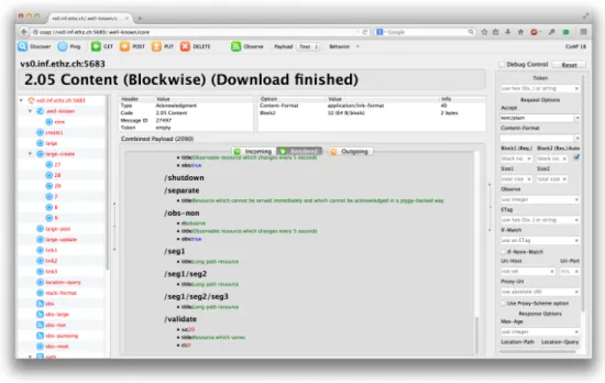
Fig 2.4 depicts a lookup on a public CoAP test server provided by Research Group for Distributed Systems at ETH Zurich [24]. This demonstration was possible using Firefox’s extension called Copper (Cu), a CoAP protocol handler [25]. The GET request to the standard well-known URI returned a list of resources preset on that CoAP’s server Resource Directory. Each of these returned URIs also provide its resource and content type and the observable flag.
It is possible to get semantics on these returned links, like “rt=ipso:dev-ser”, indicating that the specific resource (/dev/ser, for instance) adopted the Application Framework designed by IPSO [26]. This is very important for interoperability purposes and is properly detailed in the dedicated ”IPSO Alliance” section. LWM2M [22], as another example, is a very powerful protocol which defines data semantics to be used with CoAP, where resources are managed as standardized objects. As LWM2M is primarily a simple Device Management protocol that can be used with CoAP, it is also detailed further, given its importance.
Figure 2.5: HTTP-CoAP proxying mechanism. [27] HTTP and CoAP Proxying
It is possible to proxy to and from HTTP, as seen in Fig 2.5 This allows for interconnectivity all the way from the device domain to the network domain, using a proxy either at the network level or gateway’s, as represented. Fig 2.6 represents this proxying example together with caching mechanism. This is an important feature for constrained environments, as it is easy to think of a network application constantly querying a constrained device - with this caching feature, the application does not need to implement CoAP itself since there is a proxy on the gateway and, secondly, because it saves the device’s battery and network bandwidth by having only one interaction for each certain amount of time (CoAP’s max-age option). By deploying an HTTP-CoAP proxy, HTTP clients are able to interact with the CoAP server. This is possible by appending a coap or coaps URI in the HTTP request. Once the proxy entity receives this HTTP GET request, it forwards its builtin CoAP’s URI GET request method to the CoAP server and responds to the original HTTP client. Likewise, the same mechanism is applied in a CoAP-HTTP proxy.
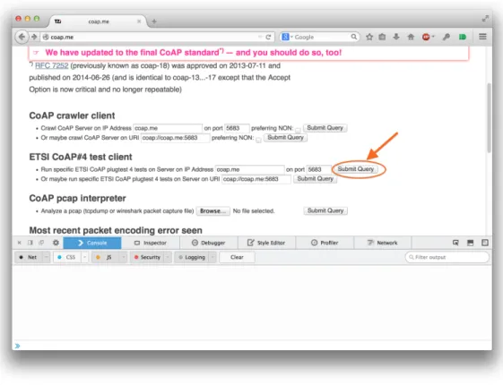
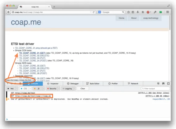
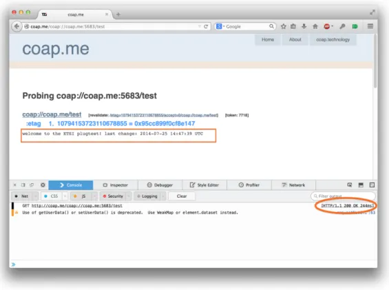
Fig 2.7, 2.8 and 2.9 showcase an example of an HTTP-CoAP interaction using Firefox as an HTTP client. The web page used to test this functionality was the publicly available http://coap.me [28] - Carsten Bormann’s, one of the authors of CoAP’s RFC, debug website. The first Fig 2.7, shows the initial interaction with the website. This webpage has a built-in HTTP-CoAP proxy on its side, and, as Fig 2.8 denotes, the previously clicked button shown in Fig 2.7 has now returned a number of links we can interact to - in other words, resources available and their URI. Once we send an HTTP GET request with CoAP’s URI inside, http://coap.me/coap/://coap.me/test (which the link pointed out by the arrow), we get the HTTP 200 OK response code from the proxy and the resulting Payload response from CoAP’s GET request, as shown in Fig 2.9.
Figure 2.6: CoAP - Proxying and caching. [27]
Figure 2.10: CoAP’s Observation feature example [29] Observation Feature
It is also possible to establish a subscription communication using CoAP’s observation feature. Simply put, this means that once the client makes a GET request with the observer option set, the server will deliver every new representation as the state of the resource changes. The client must set a token code for the first GET request and the server will send notifications with this same token for each update message. The client can observe different resources at a time.
Fig 2.10 depicts this feature. The first time the client sends a GET with observe (’obs’ option set to 0 means Register), the Server adds it to the list of interested, and will send out notifications, with the same originally defined by the client token, together with a sequence number for re-ordering purposes on the Client side. The Server interprets the Client as subscribed as long as it ACKs and will remove it from the list if it either deregisters (’obs’ option set to 1), rejects a notification or the transmission times out after several transmission attempts. [29]
Block Transfer
Block Transfer is a CoAP feature designed to support transmission of large data. In these typical environments, sometimes there is a need to transfer large information like a complete log file or a new firmware as an update. With HTTP, TCP handles this by breaking down the data into multiple packets and controlling the information flow. As CoAP does not use TCP, fragmentation should be avoided for efficiency reasons , and so this new mechanism was introduced[30].
and will keep on responding to the client with new blocks of information without a connection setup.
2.2.2 MQTT
MQTT (Messaging Queue Telemetry Transport) is a lightweight network protocol for publish/subscribe type of messaging. It was originally designed in the late 1990s with simplicity in mind [31] and so the final specification is very simple and small (42 pages vs. 112 found at CoAP’s) [32]. It is now backed by IBM and is currently undergoing standardization at OASIS [33].
MQTT allows for messages to be publish to one central Broker (server) and then to many other entities (clients), if they have subscribed to the same particular topic, as depicted in Fig. 2.11. When an application publishes messages to topic “A”, for example, all other applications, who had previously subscribed to that same topic, will immediately receive the same message. Its verbs are just connect, subscribe, publish and disconnect and, with this pattern, it is possible to efficiently distribute data from one to one and one to many in a simplified mechanism.
Topics are what differentiate which data clients want to receive. With it, it is possible to define semantics like “thermometer”, “pump”, for example. They define to who shall the Broker forward the message to and its powerful wildcard support makes it a very flexible and smart routing mechanism. Wildcards define the level of hierarchy: “+” means single-level, “#” means multi-level. Fig. 2.12 illustrates this mechanism. A client subscribed to “/sensors/health/+” would receive messages from topics “/sensors/health/hearth_rate/” and “/sensors/health/glucose”; similarly, a subscription to “/sensors/health/#” would subscribe to all nodes below this level, which are “/sensor/health/heart_rate/”, “/sensor/health/glucose/”, “/sen-sor/health/glucose/patient_1” and “/sensor/health/glucose/patient_2”. It is also possible to use both in the same sub-scription, making it very efficient to subscribe to numerous different topics with one request only.
Its rich yet simple incorporated QOS allows for three different levels of messages delivery:
Figure 2.12: MQTT’s wildcard support example
network layer and its best efforts mechanisms. Because there is no implementation of data delivery validation (ACK/NACK), there is no way to determine if messages actually got delivered. Should be used by typical WSN nodes which either stream frequent messages or its content is not vital.
• Level 1 (”At least once”). Ensures that messages arrive, but duplicates may occur. The duplicates messages can be discarded by analyzing the message ID.
• Level 2 (”Exactly once”). Ensures that messages arrive exactly once. No duplicates occur at the expense of bigger overhead. Needed for critical scenarios such as flight control where duplicate or lost messages can not occur. Protocol version 3.1, latest one as of this writing, now features authentication username/password mechanism at the API level, which is sent via the initial CONNECT message. However, as this data is transferred over as clear text, network encryp-tion (like SSL/TLS tunneling, or a VPN with IPSec support) should be used. Other mechanisms allow also for encrypencryp-tion, although this is not part of the specification. Brokers like mosquitto [35], one of the most widely used, supports encryption based on both certificate and pre-shared-key and even authorization via ACL (Access Control List), which controls client access to topics.
As it was designed for low-bandwidth and high latency networks (satellite and GPRS), it possesses interesting features for IoT systems and its constrained devices such as a small code footprint, low overhead, bandwidth efficiency and QoS (needed for this typically unreliable domain) mechanisms. This features are much needed in IoT for two reasons: first, at the device/gateway domain area, it allows devices to sleep and wake up to simply message the central Broker (detailed further), using any content format as it is data agnostic, with very little complexity (2 bytes header, the smallest packet size) while at the same time providing QoS; secondly, at the network domain, it allows for efficient one-to-many distribution of data with assured delivering. However, it may not always be the best suited protocol, given its dependency on TCP. TCP,
which provide only a packet size of 128 bytes long (not accounting for headers) and very low bandwidth of 250 kbit/s. However, due to its low dependencies, it can be adopted in every network, as long as it provides bi-directional data transfer between any node and a particular gateway. [36]
Its overall architecture differs only from the original MQTT in a sense that it adds a MQTT-SN Gateway between the client and the MQTT Broker. Other fundamental different features which were introduced to address these devices’ characteristics were: shorter topic ids of only two bytes long instead of long strings (support for small messages length), and a new “keep-alive” procedure which allows a device to sleep while it is destined messages are buffered at the server/gateway and delivered later when it wakes up. More importantly, SN depends solely on UDP, instead of TCP. Fig. 2.13 represents MQTT-SN’s architecture. Besides the aforementioned MQTT-SN Gateway, there can also be a MQTT-Forwarder. The Gateway is in charge of translating MQTT-SN protocol into MQTT from one domain (Zigbee, for instance) to any other one that supports the TCP/IP stack where the MQTT Broker is located. The Forwarder does not translate one protocol to another but it forwards the message from one network to the other. As it supports multiple Gateway/Forwarders, the protocol helps to mitigate typical loss of messages (due to network’s inherit low bandwidth and high link failure rates) by offering load sharing and redundancy services.
2.2.4 Comparison
As CoAP follows the HTTP approach, it is a document transfer protocol. The most important difference is that it was designed for constrained devices, adopting UDP instead of TCP and packet creation simplicity. However, it still follows a client/server model which translates into an one-to-one type of data flow. It does have a new “observe” approach, but it is not as efficient as a real pub/sub protocol like MQTT[-SN]. Unlike MQTT[-SN], CoAP’s Web Service oriented architecture allows for a seamless integration in the Web and interoperability with common RESTful Web Services by making use of simple proxies. On the other hand, MQTT-SN simple approach allows for an efficient one-to-many communication at the expense of not being directly integrated, as easily, into RESTful Web Services. Furthermore, MQTT[-SN] is payload agnostic
Figure 2.13: MQTT-SN Architecture [34]
and, being so, each application must know before hand how to process the representation; CoAP, in the other hand, allows for content negotiation. Also, CoAP’s Resource Discovery allows for a typical sensor to act more as a server than as a client. This added complexity allows for much simpler end-to-end direct interaction with the sensor, but one may also encounter NAT problems. As MQTT makes use of TCP, it is connected-oriented TCP connection to the server results in non-existent NAT problems; however, once again, it may only be used in devices with TCP/IP support.
To conclude, it is important to understand that each protocol serves its own purposes. Both have advantages and disad-vantages and its adoption depends solely on the particular scenario/application - it is best-suited messaging pattern, need for resource discovery and Web integration, etc.. Not every IoT/M2M system will use the same protocol - in some cases, it may even be best to use both. However, these are the ones mostly used [4] and so, IoT/M2M System Architecture SDOs (Standards Developing Organizations) must take this into consideration, providing, for instance, intrinsic protocol-binding for greater flexibility and scalability.
2.3 Conclusion
This chapter has showed how entities like IETF are working on specific protocols for IoT, adapting some of the existing technologies to the typical constrained environments most “things” will reside on. As there is a need to bring IP connectivity to these “things”, protocols like 6LoWPAN, Zigbee IP [37] and even the next generation of Bluetooth Smart [38, 39] are proof that there is a need to adapt the typical low-energy RF technology to IP. At the application level, new lightweight protocols are also needed and some have been created specifically for IoT, like CoAP and MQTT-SN. The Internet of Things is still in its
independently of the underlying network and technology. From an industry standpoint this simply means that it will enable a faster and reliable deployment of a complete interoperable M2M solution. It is ETSI’s goal to re-use and integrate already existing standards and technology. The term M2M is often used, while IoT is not, but they all serve the same purpose -all standards have M2M in its name, but the specification acknowledges that it is also designed for IoT, as M2M is at IoT’s core. Fundamentally, IoT differentiate itself from M2M simply because it has implicitly associated features that may not be present in M2M solutions, like context-aware (self adaptation to the environment), collaboration (inter-exchange of smart object’s data) and cognition (autonomous systems making sense of data, producing intelligent decisions), which, in others words, means no Human intervention. The next sections will then detail the latest standards and proposals for a common IoT System Architecture.
3.1 ETSI M2M
ETSI TC (Technical Committee) M2M was established in January 2009 [40] and it follows an open approach, by integrating and cooperating with different organizations and by publicly publishing latest drafts and final TR (Technical Requirements) and TS (Technical Specifications) [41]. It is organized into 5 WG (Working Group):
ETSI TC M2M acknowledges that M2M solutions will serve different applications such as e-health, smart metering, smart grid, automotive and connected consumers. Because of that, studies were made and specifications have been released. These are Technical Reports (TR) often detailing different use cases which are later addressed as part of specifications in Technical Specifications (TS). Particularly important for IoT is TR 101 584 [42] where a “Study on Semantic support for M2M Data” was conducted. In this Technical Report, a study on the “benefit, feasibility and potential requirements for the support of semantic information on application related M2M Resources in the M2M system” was made. It does not support the idea of defining semantics to be included in the standard, but instead studies the mechanisms needed to create and handle such information. Use cases are presented and most of them related to e-health, demonstrating the benefits for the whole M2M ecosystem. It was also investigated discovery mechanisms to be used within the system architecture, taking into account how other solutions (like CoAP’s) could be used within ETSI’s M2M architecture. Such mechanism could enable, among others, feature like “simplified configuration of M2M applications and more intelligent adaptation to changing situations”. This abstraction level would provide the information - much needed by smart applications - to create knowledge out of it and correlate events between other applications and/or IoT/M2M systems.
Current vendors and organizations have their own vertical solution with proprietary functionalities, transport and network protocols and communications infrastructure. This paradigm leads to more expensive and complex solutions, larger time to market and lack of intercommunication with other M2M systems. To fight all this, an horizontal solution with a common set of service functions and open middleware platform is being developed by ETSI TC M2M, which is network and application-agnostic, but aware [43]. It is based on existing standard and technologies (GPRS, WiMAX, WLAN, UWB, Zigbee, 6LowPAN, CoAP, HTTP, for example) and it provides a generic set of capabilities for M2M services and a framework for developing services independently of the underlying network. With it, it is possible to break down current silos.
3.1.1 Architecture
To summarize ETSI’s M2M System Architecture, one can break it down into three main area domains: M2M Device Domain, M2M Network Domain and M2M Application Domain. Across these domains are three standard Reference Points connecting them, by means of a set of Service Capabilities. Figure 3.1 depicts the high level architecture. The Service Capabilities are present in each SCL (Service Capabilities Layer) - DSCL, GSCL and NSCL (Device, Gateway and Network, respectively). A
Figure 3.1: ETSI’s M2M High Level System Architecture [44]
RESTful architecture style was adopted, where information is represented by resources. The SCL holds this standardized resource hierarchical tree structure (Fig 3.2). The information present on each resource can then be exchanged between the different SCL over the Reference Points (dIa, mId and mIa), via standardized procedures. As it follows a RESTful architecture, it is possible to manipulate the information using CRUD methods (Create, Read, Update, Delete) in a Client-Server model. These SCL allow for management of information related to applications and devices like registration, access rights, security and authentication, data-transfer, subscription/notification and group management [46] [47]. All of this is achieved by RESTFul operations using HTTP or CoAP, as CoAP binding is also part of the standard, over the standardized resource tree. As a simple example of how this RESTful Architecture works across the SCLs, a diagram is shown 3.3 denoting a typical scenario where a sleepy Device (D) sends data to a Network Application (NA). First, the Device writes data to the DSCL through NSCL (UPDATE verb); then, the NSCL notifies the NA of that resource change (notify means either a response of a RETRIEVE or an UPDATE, if a polling or the asynchronous mechanism is used, respectively); at last, the NA reads the new resource change. For the sake of simplicity, the illustrated diagram represents only the events flow, hiding all methods, protocols and responses used in real applications.
The different Reference Points mIa, mId, dIa, and mIm have their own purpose. They all, fundamentally, offer the same mechanisms, but at different domains. dIa offers a generic and extendable mechanism for Device Application (DA) and Gateway Application (GA) to interact with DSCL (Device Service Capability Layer) or GSCL (Gateway Service Capability Layer). This allows the applications to register in the SCL, request read/write permissions on the NSCL, GSCL or DSCL, subscribe
Figure 3.3: Simple use of SCL resources to exchange data (adapted from [48])
and notify to/of specific events and request managing capabilities of groups. mIa functionality is identical to that of dIa, but the interaction is between the Network Application (NA) and the NSCL (Network Service Capability Layer) and it may be used to to request device management actions like firmware update. Likewise, mId follows the same pattern, but over IP connectivity between DSCL/GSCL to NSCL backed by security features. The last Reference Point defined in the Functional Architecture [48], mIm, is a special one used only for inter-domain across different M2M Service Provider; its capabilities differ from mIm when there is no NSCL registration - if this happens, the offered capabilities are some of those offered by mIm like request to read/write information in the NSCL, GSCL or DSCL across two different M2M Service Providers, if properly authorized to do so. The previously mentioned device management capability is possible because of BBF TR-069 [49] and OMA DM [50] compatibility and integration with the standard [51].
3.1.2 OneM2M
ETSI was not the only SDO (Standards Development Organization) working on a M2M architecture - others had their own solution as well, which would lead to interoperability problems and a slow development of the global M2M market. To avoid any duplication of work between SDOs involved in the same domain, and to agree on a truly global standard M2M architecture, oneM2M was born. In January 2012, seven SDOs - ARIB, ATIS, CCSA, ETSI, TIA, TTA, and TTC -, have agreed on a Global Initiative for M2M Standardization [52]. As they have agreed on an open collaboration with other interested organizations and parties, many others have joined in to contribute in different levels of functionality - OMA, responsible for LWM2M, IPSO Alliance and Continua Health Alliance, as Partners Type 2, which were mentioned in this work, are some examples. Six months later, in July 2012, the oneM2M partnership project was established having ETSI TC M2M work
Figure 3.4: oneM2M Functional Architecture [59]
being transferred over to form its basis. Fundamentally, oneM2M Partnership Project aims to establish a cooperation “in the production of globally applicable, access-independent M2M Service Layer specifications, including Technical Specifications and Technical Reports related to M2M Solutions” [53].
OneM2M ’s ambition to release specific Technical Specifications on different transport layer protocol bindings (like CoAP, HTTP, MQTT and, possibly, XMPP) combined with the inclusion of device management, abstraction layers and semantics view make it a very compelling uniform Standard. The Candidate Release [54] was available for public commenting on August 2014 which already specifies the functional architecture, CoAP and HTTP protocol bindings [55, 56] and mappings to device-management related protocols like OMA DM, OMA LWM2M and BBF TR-069 [57, 58].
Its functional architecture is depicted in Fig. 3.4 and one can easily spot its resemblance to ETSI M2M. Like ETSI M2M, the resources described in the architecture can all be interacted via a RESTful API and its primitives, the service layer messages sent over Mca and Mcc reference points, are then mapped to the appropriate transport layer protocols like CoAP, HTTP and MQTT [60]. Bellow these transport layer protocol bindings is the underlying network to which oneM2M will also define a set of bindings to. This last feature will be possible via NSE (Network Services Entity) which provides services of the underlying network to the CSEs (Common Services Entity), like device management, location and device triggering. The services provided by CSE are called CSF (Common Services Functions) and these are the key services functions with which AE (Application Entity) and CSEs interact with via the appropriate reference points. These are detailed in Fig. 3.5 . The interaction between AE and CSE is made by primitives, as illustrated in Fig. 3.6. Each CRUD (Create, Update, Retrieve and Delete) operation is mapped to one or more primitives which is then further mapped to transport layer protocols like HTTP, CoAP or MQTT.
Figure 3.5: oneM2M - Common Service Functions residing in CSE [59]
Application data. In essence, OMA Lightweight M2M (LWM2M) is built upon CoAP and DTLS protocol with bindings to UDP and SMS (for Cellular Device management) and offers an extensible Object and Resource model for application semantics which can be published to OMA public registry. This use of known application semantics provides interoperability and abstraction between different IoT/M2M systems.
3.2.1 Overall High Level Functionalities
The Device Management functionalities are as follows:• Bootstrapping: automatically connect the device to the right server using key management. • Device Configuration: change parameters of the device and network settings.
• Firmware Update: Over-the-Air (OTA) software updates (to overcome latest security problems, apply patches, en-hancements, etc.)
• Fault Management: automatic error reporting from the device and ability to query it. For debugging purposes such as network unreachability and misconfigured applications and/or services.
And, as it is also a solution for Application’s Data, it also allows for:
• Configuration & Control: in-app configuration of settings (control commands to define new Application’s parameters) • Reporting: Notification mechanism to alert for new sensor values, alarms and events.
3.2.2 Architecture
Its architecture is simpler than ETSI’s and oneM2M’s. Fig 3.7 illustrates its components and relationships between them. With LWM2M’s architecture, there is a small LWM2M Client library in a constrained device which uses the standardized interfaces to manage the built-in Objects created by the Device Manufacture and/or the Application Developer. Managing
Figure 3.7: OMA Lightweight M2M Architecture [62]
these known objects between the Client and the multiple M2M Applications, as long as they have authorization to do so, is, therefore, very straightforward, allowing for greater interoperability and abstraction when making use of standard Objects (detailed further). The LWM2M server works as an intermediate between the M2M Applications and the Devices itself - it can command the Device to Read, Write, Execute, Create or Delete Objects and its resources (also detailed further). All of these commands are sent to the Device via four interfaces:
• Bootstrapping: it is possible to do pre-provisioning out of the SIM card or flash memory, or initiate the configuration mechanism between Client and Server by making use of initial shared keys, server configuration and ACL (Access Control List), for example.
• Registration: the LWM2M Client can alert the LWM2M Server of its existence and capabilities, by means of Resource Directory (another IETF standard).
• Management & Service Enablement: used when the Server wants to send operations and commands to the Client. Allows for Device Management and Service Enablement over the previously announced, by the Client, Objects and Resources. The Client responds via this interface as well.
• Information Reporting: allows for periodically report of resource information by the LWM2M Client in case of triggered events and/or alarms. The notification mechanism is possible due to CoAP’s observation feature.
Figure 3.8: LWM2M Object Model [63]
The stack is very small as well, as it uses simple protocols and technologies. CoAP, DTLS and UDP are all lightweight enough, efficient and secure to be used in constrained environments and SMS binding is optional but a must for Cellular use. DTLS is used between LWM2M Server and LWM2M Client to secure all the information exchanged between these two endpoints.
3.2.3 Object Model
As stated before, LWM2M structure information resides on Objects and their Resources. These work as an URI formatted as
/{Object ID}/{Object Instance}/{Resource ID}
Hierarchically, an Object may contain several Resources, which, in turn, may have multiple Instances. Each Object as associated an ACL Object, defining which restrictions are imposed to that particular Object (managed by the Server). As it makes use of CoAP, the three known verbs GET, PUT, POST are also present on each Resource as Read Write and Execute operations respectively. Like UNIX files, all sorts of combinations are possible: some might allow the reading operation along writing or simply execution operation, etc., as showcased on Fig 3.8
To access an URI, the machine needs only to GET, POST or PUT a small and easy to parse URI as small as, for example, 2/0/1. Objects and Resources are identified by a 16-bit integer, while an Instance needs only an 8-bit Integer. The resource’s payload can be represented as pain text and as binary TLV or JSON for Objects or Resources arrays.
One important aspect of this model is that its cooperation with other M2M/IoT systems is very simple, since the definition and registration of Objects is open for third parties (Enterprises or SDOs). OMA itself has defined 8 built-in Objects to be used
3.3.1 IoT-A
IoT-Ais a FP7 program [64] whose main goal is to develop an Architectural Reference Model for the Internet of Things. The project started in 2010 and finished three years later, in 2013, but its resulting work has passed on to IoT Forum. The authors of such project have recognized the current IoT implementations as not really Internet of Things, but rather an Intranet of Things, given the nonexistent of an holistic approach to implement such systems. The latest version of their Deliverable about the “architectural reference model for the IoT” [65], which dates July 2013, the authors have justified the need of an Architectural Reference Model (ARM) for IoT to support both a common understanding of the IoT domain (Reference Model) and a set of frameworks and guidelines for businesses who want to create their own compliant IoT solution (Reference Architecture). The conjunction of this Reference Model, the Reference Architecture and a set of Guidelines are what constitutes the ARM. For the authors, “the interoperability of solutions at the communication level, as well as at the service level, has to be ensured across various platforms” so that it is possible to achieve their envisioned IoT.
In order to achieve the ARM which will serve as a the matrix for the final concrete architecture, the project specifies a logical methodology. It is important to thoroughly study existing architectures and solutions (State of the Art - SOTA) which will enable the establishment of, first, a Reference Model and then a Reference Architecture, as can be seen in Fig. 3.9. First, it is important to know that the authors have defined such a Reference Model and a Reference Architecture having in mind OASIS’s definition of such. Before analyzing both, one must understand a Reference Model as a “minimal set of underlying concepts, axioms and relationships within a particular problem domain, and is independent of specific standards, technologies, implementations, or the concrete details” [66]and a Reference Architecture as “an architectural design pattern that indicates how an abstract set of mechanisms and relationships realizes a predetermined set of requirements. It captures the essence of the architecture of a collection of systems. The main purpose of a reference architecture is to provide guidance for the development of architectures. One or more reference architectures may be derived from a common reference model, to address different purposes/usages to which the reference model may be targeted.” [67]
Figure 3.9: IoT Architectural Reference Model building blocks
The ARM defined by the project is not, in itself, an IoT Architecture - it is a generic architecting framework which can derive a concrete IoT Architecture. This process of achieving a concrete IoT Architecture depends solely on the architect, and the resulting analysis of the project’s guidelines, perspectives and models.
As the Reference Model provides the highest abstraction level for the definition of an ARM, it includes a set of models related to the IoT domain:
• IoT Domain Model - top-level description;
• IoT Information Model - how IoT knowledge is going to be modeled;
• IoT Communication Model - to better understand specifics about communication between many heterogeneous IoT devices and the Internet as a whole.
In the other hand, the Reference Architecture, is the one responsible for building compliant IoT architectures. It does not provide concrete application architectures, but rather a set of abstract mechanisms which businesses and implementors of the final concrete IoT Architecture must take into account (Views and Perspectives). Finally, the last block of the ARM, as represented in Fig. 3.9, is the “Guidelines” which is an extensive work done by the project (available in [65]). It offers recommendations and discusses how the previously given Models, Views and Perspectives can derive in a concrete Architecture. This are, fundamentally, Design Choices which are most important to businesses and overall IoT Systems implementors. Design Choices like real-time access to information, security features, semantics, etc, are some examples of architectural choices which forms instances from the Reference Architecture.
To summarize, it is the combination of the large SOTA analysis (and its resulting set of possible functionalities, mechanisms and protocols) with a set of Design Choices that offers IoT System Architects the set of protocols, functional components
(version 3, released in July 2013 [65] is a 482 pages long document), and for this matter, any further detailing would be out of scope. IOT Forum acknowledges that the ARM now needs a set of re-usable profiles [68]. These profiles will take ARM one step forward to achieve broad adoption as these profiles are expected to be adopted by IoT system architects. With this future work, the ARM will evolve from a generic architecting framework to a set of pre-build concrete architectures, taking away much of the work previously needed by actual architects.
3.3.2 IPSO Alliance
The IPSO Alliance main objective is to educate, document and support the use of IP for the IoT, while defining the “appropriate protocols, architecture and data definitions for Smart Objects so that engineers and product builders will have access to the necessary tools for “how to build the IoT RIGHT”” [69]. It is a much needed Alliance for IoT, giving their efforts on the use of semantics for the whole IoT. These semantics help to represent, in a standard way, common resources like temperature, light control and power control, as examples.
IPSO has published a guideline [26], which should not be recognized as a standard, on how to define Smart Objects using a RESTful design for common M2M Applications such as Home Automation and Building Automation. This defines how a Smart Object can represent its available resources and how to interact with other Smart Objects and backend services, using the defined set of REST interfaces. The goal here is to show vendors simple guidelines on using IP and Web-based technology to develop and rapidly test interoperability among devices and services. Following these guidelines assures compatibility with the previously mentioned OMA LWM2M. As stated before, third party SDOs can define and register Objects on the OMNA -and that is what IPSO has done. OMNA LWM2M Object & Resource Directory [62] lists the resources already defined by the IPSO Alliance. For example, Table 3.1 describes the “Luminosity Sensor” Object registered by the Alliance with an Object ID (3301) provided by OMNA.
In September 2014, the Alliance has released a guideline called “Smart Objects Starter Pack 1.0” [70] which list and details 18 IPSO Smart Objects based on OMA LWM2M’s object model specification, like the one represented in 3.1. This type of
that can be measured by the luminosity sensor. The unit used here is Lux (ucum:lx). Table 3.1: Example of a LWM2M Object defined by a 3rd Party SDO and registered at OMNA.
work represents IPSO Alliance’s effort on supporting an IoT where Smart Objects can easily integrate the current Web. Their support on specific technologies and protocols (6LoWPAN, UDP, CoAP and LWM2M) justifies the ease of a simple IoT/M2M system architecture where common Objects can easily be mapped between constrained devices (6LoWPAN and LWM2M) and the whole Web (meaning mobile applications and services) through HTTP and IPv6 by making use of the appropriate Content-Type and access methods (HTTP protocol binding is also defined in LWM2M).
3.4 Comparison
Each standard has its own particularities, and, as it happens with transport layer protocols, each serves a purpose. One standard does not fit all, but a combination might be a good solution. As IoT-A is not really a functional architecture, but an architecting framework, not much can be said at this point; however, this might change in the future as IoT Forum will continue to work its defined ARM so that a a set of re-usable ARM-profiles can be built, to be immediately adopted by IoT Architects. In a much more advanced phase, is ETSI’s M2M architecture. It is flexible enough to be widely adopted by either IoT/M2M architects and Application/Services Developers. Its REST API combined with the decoupling of different Services Layer allow for rich applications to be build, while inter-exchanging information and application data with each other, extending their functionality. However, it was not really designed to be supported in small and constrained devices. For a device to be fully compliant with ETSI M2M, its application (DA - Device Application) must support the correct HTTP or CoAP (if built-in bindings or Interworking Proxies are supported) methods to specific URIs with complex XML data.
For real constrained devices, the OMA DM included in ETSI M2M functional architecture might be too complex for such devices. The Remote Entity Management (REM) Service Capability must be supported at both Device/Gateway level and Network level. As the OMA DM standard was initially conceived for not so constrained devices and environments, its natively inclusion in ETSI M2M might be obsolete for real IoT systems. ETSI has laid the foundations for a standard M2M architectural
issues). These combined with application data (send and retrieve data using CoAP and UDP/SMS) makes it a very compelling option for an IoT system architect. Also very important is OMA’s Naming Authority (OMNA) which allow for simple known semantics to be registered through its extensible model object - like the ones defined by the IPSO Alliance. As it is also very light, most constrained devices need only a small library to support the whole protocol - device manager and application data.
Finally, OneM2M seems to tackle both ETSI M2M’s and LWM2M’s cons by combining the two. It is a more modern standard that takes ETSI M2M as its basis while offering binding to most commonly used IoT protocols and tools like MQTT and Web Socket (still a work in progress, as evidences found in [60] and [71] suggest so). Its LWM2M integration makes OneM2M the most complete standard ready to target both M2M and IoT solutions supporting all functionalities and services needed by both while, at the same time, providing a concrete way for Application and Services Developers to interact with. This is what is needed in IoT to make way for richer, smarter and interoperable Applications across every domain.
3.5 Literature Review
As most of the protocols and standards described earlier are fairly recent, they have not been very referenced in the literature when deploying IoT systems. The concept itself is present in such systems, but only a small part of them are using the specifically-designed protocols such as 6LoWPAN, CoAP, MQTT and architectures and frameworks like ETSI’s M2M Archi-tecture, oneM2M or LWM2M. For this matter, three different recent articles that are either related to the proposed solution or announced as an IoT solution, are detailed and compared.
A recent work was published on a “Middle East Conference on Biomedical Engineering (MECBME)” in February 2014, presenting an Ubiquitous Healthcare System [72] as a prototype for the authors’ future system. This system makes use of 6LowPAN between the nodes and the Edge Router (ER) and a custom proprietary application on the Base Station (PC) to receive the transmitted UDP packets to then make it available on the internet using either SensorMonkey and an UbuntuOne
Figure 3.10: Representation of the System Architecture defined in [72]
Server, as represented in Fig 3.10. The Base Station has a running C program that listens for UDP Packets in the interface provided by the SLIP (Serial Line Interface Protocol) utility. This C program is multi-threaded and, being so, it is composed of two TCP Servers who are responsible for sending the previously obtained data to SenseMonkey’s platform. This platform, once an account is created, provides a way of registering the sensors and subscribe to them by inserting the Base Station’s IP and the dedicated TCP ports.
When analyzing the typical and the already-defined protocols and standards to be used in IoT, [72] makes use of only one of them: 6LoWPAN. The data transmitted via 6LoWPAN relies solely on UDP and makes no use of standard application layer protocols like CoAP or MQTT[-SN]. This accounts for interoperability issues. Further more, the real time streaming process relies solely on non-standard applications (SensorMonkey and UbuntuOne Server). If another application (as the author’s Remote Monitoring) wanted to access this streamed data, they would also have to interact with SensorMonkey’s website using the original ID and key to first request a connection and a subscription of the streaming data - SensorMonkey provides a JavaScript client which can be used to interact with its service. This is not a practical solution and makes it very hard to autonomically interact with other IoT Applications. The other adopted method relies on a synchronization of the sensed data, using UbuntuOne cloud service, once the Base Station writes new data into temperature’s and ECG’s files. After having the data stored into the respective files, a graphical Matlab client reads the data and plots it.
Although there is no precise information on the hardware used, the authors do claim that the sensor nodes made use of Zolertia motes (MSP430 + CC2420). As the ER (Edge Router), as descried by the authors, is the responsible node for converting IPv6 packets to 802.15.4 packets and vice-versa, and it forwards the received packets via USB to the Base Station, it is assumed that the hardware used was either Z1 Starter Platform or Zolertia Gateway. These components, when adding the full-fledged PC as the system’s Base Station, makes up for an expensive solution. Zolertia’s online store price tags the components as:
![Figure 2.2: 6LoWPAN routing model “Route-Over” [16]](https://thumb-eu.123doks.com/thumbv2/123dok_br/17685412.826926/31.892.224.670.182.390/figure-lowpan-routing-model-route-over.webp)
![Figure 2.5: HTTP-CoAP proxying mechanism. [27]](https://thumb-eu.123doks.com/thumbv2/123dok_br/17685412.826926/34.892.245.627.177.460/figure-http-coap-proxying-mechanism.webp)
![Figure 2.13: MQTT-SN Architecture [34]](https://thumb-eu.123doks.com/thumbv2/123dok_br/17685412.826926/42.892.186.710.192.445/figure-mqtt-sn-architecture.webp)
![Figure 3.1: ETSI’s M2M High Level System Architecture [44]](https://thumb-eu.123doks.com/thumbv2/123dok_br/17685412.826926/47.892.163.722.169.517/figure-etsi-s-m-m-high-level-architecture.webp)
![Figure 3.2: SCL’s standardized resource structure tree[45]](https://thumb-eu.123doks.com/thumbv2/123dok_br/17685412.826926/48.892.136.758.338.845/figure-scl-s-standardized-resource-structure-tree.webp)
![Figure 3.3: Simple use of SCL resources to exchange data (adapted from [48])](https://thumb-eu.123doks.com/thumbv2/123dok_br/17685412.826926/49.892.191.703.171.445/figure-simple-use-scl-resources-exchange-data-adapted.webp)
