1
A three-dimensional ring-array concentrator solar furnace
D. GARCIA, D. LIANG*, B. D. TIBÚRCIO, J. ALMEIDA AND C. R. VISTAS
CEFITEC, Departamento de Física, FCT, Universidade Nova de Lisboa, 2829-516 Campus de Caparica, Portugal *Corresponding author: dl@fct.unl.pt
Abstract
A single ring-array concentrator solar furnace unit was firstly modeled analytically, and then optimized numerically by ZEMAX® and ANSYS® software, reaching a temperature of 3778 K, nearly equivalent to that of a medium size solar furnace with 3.14 m2 collection area. A novel three-dimensional ring array concentrator solar furnace was subsequently proposed and analyzed. It consisted of five single ring array concentrators, forming a compact box-shaped solar furnace with an opening at the rear side for an easy access to a common focal spot in the center. Based on the edge-ray principle of non-imaging optics, 3.53 times higher concentration ratio was analytically calculated for this three-dimensional solar furnace, as compared to that of the medium size solar furnace, leading to significantly enhanced thermal and optical efficiencies. The temperature performance of the three-dimensional ring-array concentrator furnace as a function of receiver size and collector area was analyzed numerically and compared to that of the medium size solar furnace. For a 5.68 mm diameter spherical receiver and large collection area varying from 3.14 m2 to 100 m2, 1.1 times gradual enhancement in the maximum attainable temperature was calculated for the ring array concentrator furnace. More importantly, its average and minimum temperatures were significantly improved by 870 K and 1140 K, respectively, as compared to that of the medium size solar furnace. With convection loss, the 3D RAC solar furnace also more efficient in attaining maximum temperature than that by the parabolic mirror furnace. In addition, the three-dimensional ring-array concentrator also presented a significant tracking error compensation capacity in relation to that with the medium size solar furnace.
Keywords: Ring-array, solar furnace, three-dimensional, temperature, parabolic mirror,
2 Nomenclature
Subscript
∆𝑎𝑛 Ring width (mm)
ain Ring inner aperture (mm)
aout Ring outer aperture (mm) C Concentration ratio
dt Ring thickness (mm)
ha Ring height correction (mm)
hf Focal length (mm)
Hn Ring maximum height (mm)
I Solar radiation energy per surface unit (W/m2)
N Ring number
r Radius (mm)
RoC Radius of curvature (mm)
S Collection area (m2) Th Receiver temperature (K) T0 Ambient temperature (K) Greek Letters ε Emissivity η Efficiency (%)
θa Sun-Earth acceptance half-angle (°) σ Stefan-Boltzmann constant
𝜙 Diameter (mm)
3
1-Introduction
Energy consumption of depletable and pollutable resources is an ever-growing topic of concern among nations. The resolution for these problems is to pledge over renewable and sustainable energy technologies that contribute in a minimal environmental footprint (Hussain et al., 2018). Solar energy is one of the cleanest renewable energy sources and considered as green energy source available abundantly. (Kalogirou, 2004).
A solar concentrating collector have several mechanisms that tracks the movement of the Sun. Single-axis tracking solar collectors, such as linear Fresnel reflectors (Kasaeian et al., 2018; Xie et al., 2011), parabolic trough collectors (Kasaeian et al., 2018) (Bellos and Tzivanidis, 2019) and cylindrical trough collectors (Winston, 1974), have maximum temperatures ranging from 300°C to 400 °C. Two-axes tracking solar collectors include parabolic dish reflectors, heliostat field collectors and circular Fresnel collectors, with which the solar rays are focused to a single spot, and capable of reaching temperatures from 2000 °C to 3800 °C (Kalogirou, 2004) (Xie et al., 2011) (PROCÉDÉS, 2018).
The first recorded use of a solar furnace was in 1695 when Georges Buffon ignited wood and melted lead using mirrors. Antoine Lavoisier built a solar furnace that reached a temperature of 1780 °C, enough to melt platinum, in 1700 (Meinel, 1979). Felix Trombe and Marc Foëx were the pioneers of high temperature solar energy research (Trombe and Foex, 1957). Their interest in this area began in the mid-20th century when they were investigating high-temperature metallurgy, inorganic chemistry of rare-earth elements, and oxide ceramics characterization.
Several institutions around the world provide the state-of-the-art high-flux solar research facilities. Table 1 summarizes attainable solar fluxes levels by each institution. The highest solar flux up to date is 16000 kW/m2, equivalent to 16000 Suns concentration factor.
Table 1 – The state-of-art solar fluxes.
Institution Collector area
(m2)
Solar flux
(kW/m2)1 Reference MSSF horizontal and
vertical axes parabolic mirror, PROMES-CNRS, France 3.14 16000 (PROCÉDÉS, 2018) Eurodish, PROMES-CNRS, France 57 9600 (Reinalter et al., 2008) MWSF, PROMES-CNRS, France 2835 10000 (2019)
ANU, Australia 500 14000 (Lovegrove et
4 Distal I, PSA-CIEMAT, Spain 44 12000 (PSA-CIEMAT, 2009) Distal II, PSA-CIEMAT,
Spain 57 16000
(PSA-CIEMAT,
2009)
NSTTF, Sandia, USA 35 5000
(Camacho-Lopez, 2019)
HFSF, PSI, Switzerland 57 5000 (Haueter et
al., 1999)
11000 W/mm2 is equivalent to one concentration factor of the Sun.
MSSF: Medium Size Solar Furnace; MWSF: Mega Watt Solar Furnace; PROMES- CNRS: Procédés,
Matériaux et Énergie Solaire - Centre National de la Recherche Scientifique; PSA-CIEMAT: Plataforma Solar de Almería-Centro de Investigaciones Energéticas, Medioambientales y Tecnológicas; ANU: Australian National University; NSTTF: National Solar Thermal Test Facility; HFSF: High Flux Solar Furnace; PSI: Paul Scherrer Institute.
These solar energy research facilities allow academic and industrial users to conduct scientific research and qualify commercial prototypes in the fields of: solar thermal electricity generation technologies (Kalogirou, 2004) (Islam et al., 2018); solar fuel production of H2, syngas, liquid
and gas hydrocarbons (Romero and Steinfeld, 2012) (Agrafiotis et al., 2014); cycles for chemical storage of solar energy for short and long duration with ZnO, CeO2, iron, silica, etc
(Datas et al., 2016); solar water treatment through desalination, disinfection and decontamination (Liu et al., 2017) (Ahmed et al., 2019); solar heating and cooling of buildings (Prieto et al., 2019); high value material synthesis and/or coating deposits of nanomaterials, new ceramics or metals, foams, catalytic layers (Fend et al., 2004); high-flux photochemistry (Funken and Becker, 2001) and photo-physics; characterization of materials behaviour and properties under extreme conditions (Fernandez-Gonzalez et al., 2018); solar pumping of laser for industrial and space applications (Almeida et al., 2015) (Liang et al., 2017).
Solar collectors are continuously being improved, parabolic ring array concentrators (RAC) are, however, much less explored. A RAC consists of a set of parabolic reflective rings mounted coaxially to avoid shading effect from either incoming or reflected light among parabolic rings. Its focal spot in the rear side of the collector is created by superposition of rays from the reflective rings. The RAC allows efficient combination of components, reducing the shadow areas between incoming solar rays and the receiver, as compared with the heliostat–parabolic mirror systems. The RAC has no chromatic aberration along its focal spot, providing higher solar concentration efficiencies as compared with Fresnel lenses. Vasylev (Vasylyev, 2003) and Mouzouris (Mouzouris and Brooks, 2009) restarted the ring array concentrator research similar to the Pyreheliophoro, a type of solar concentrator from 19th centrury (A. Gomes, 1899; Meinel, 1979). Mouzouris calculated a 2500 W/m2 solar flux with a 0.6 m diameter RAC. Innovative solar laser pumping concepts with RAC were also numerically explored (Tiburcio et al., 2018) (Matos et al., 2018).
In this work, a single RAC was firstly modeled and compared in terms of solar flux by ZEMAX® and temperature by ANSYS®, to a medium size solar furnace (MSSF) parabolic mirror at the PROMES-CNRS. For the same collection area of 3.14 m2, both concentrating systems numerically achieved nearly the same solar flux of 16 W/mm2 and equivalent
5
temperature of 3800 K. A three-dimensional ring-array concentrator (3D RAC) solar furnace composed of five single RAC units was proposed, focusing the incoming light into a common focal spot. The 3D RAC furnace was used to heat a spherical receiver from five different sides. The concentration ratio of the 3D RAC furnace was 3.53 times higher than that of the parabolic mirror, leading to considerably improved thermal and optical efficiencies. The same spherical receiver capable of absorbing the solar flux from any directions was also adopted to evaluate the temperature performance of the MSSF. The temperature performance of the 3D RAC furnace as a function of receiver size and collector area was analyzed numerically and compared to that of the medium size solar furnace. For collection area larger than 3.14 m2, 1.1 times enhancement in the maximum attainable temperature was calculated for the 3D RAC furnace. Not less importantly, its average and minimum temperatures were significantly improved by 870 K and 1140 K, respectively, as compared to that of the MSSF. With convection loss, the 3D RAC furnace scheme also offered better temperature performance than that by the MSSF. In addition, a tracking error analysis of the 3D RAC furnace was also carried out, presenting an enhanced tracking error compensation capacity as compared to that of the MSSF.
2-Design concept and methodology
2.1- Description of the single RAC solar furnace unit
The solar concentrator technology of the RAC is comprised by two parts (Fig. 1):
a set of concentric parabolic rings that reflects and concentrates the solar rays into a common focus;
a small polymethylmethacrylate (PMMA) Fresnel lens at the center of the RAC to further concentrate the central solar rays into the same focus.
6
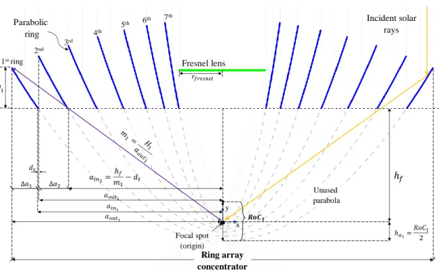
Fig. 1. Schematics of the RAC unit with seven rings. The blue lines represent the cross section of the parabolic rings and the green line represents the cross section of the Fresnel lens. Δa1 is the ring width of the first ring, 𝒂𝒐𝒖𝒕𝟏is the outer aperture of the first ring, 𝒂𝒊𝒏𝟏 is the inner aperture of the first ring, hf is the focal length, 𝒉𝒂𝟏is the ring height deviation
of the first ring, H1 is the height of the first ring, RoC1 is the radius of curvature of the first ring and m1 is the mathematical slope traced from the first ring to the origin. dt is the thickness of the ring and rfresnel is the radius of the Fresnel lens. The single RAC furnace consists of various rings, each one being a truncated section of a parabolic mirror, concentrically positioned within a circular area. The remaining central area is occupied by a Fresnel lens. Fig. 1 shows a cross-sectional view of the RAC furnace unit. Each parabolic mirror ring was analytically designed so that no ring would obstruct the focusing light path. The Fresnel lens focused the remaining central solar rays that do not intercept the rings.
2.2-Analytical and numerical methods for the single RAC solar furnace unit 2.2.1- Analytical single RAC design method
The ring-array concentrator uses the same focusing principle as a common parabolic mirror, sharing the same equations. Each ring has its own distinctive characteristics (Fig. 1), such as ring width (∆𝑎𝑛, with n as the ring number), radius of curvature (RoCn). All rings share the
same focal length (ℎ𝑓). The width of a ring is defined by the difference between the outer aperture (𝑎𝑜𝑢𝑡𝑛) and the inner aperture (𝑎𝑖𝑛𝑛); therefore, ∆𝑎𝑛 = 𝑎𝑜𝑢𝑡𝑛 − 𝑎𝑖𝑛𝑛.
The design of the RAC furnace unit is based mostly on the parameters of the outmost ring (first ring). On one hand, the outer aperture of the first ring (𝑎𝑜𝑢𝑡1) is the radius of the RAC furnace. On the other hand, the width of the first ring (∆𝑎1) determines the parameters of all other inner
1string 2nd 3rd 4th 5th 6th 7 th Fresnel lens ℎ𝑓 ℎ1= 1 Ring array concentrator Unused parabola Focal spot (origin) 𝑎𝑜𝑢𝑡1 𝑎𝑖𝑛 = ℎ𝑓 1 − 𝑡 𝑎1 Incident solar rays 1 𝑎𝑖𝑛 1 𝑡 𝑎𝑜𝑢𝑡 𝑎 ` 𝒐 𝟏 x y Parabolic ring 𝑓 𝑛
7
rings, such as the width, positional height, radius of curvature, alignment, dimension and position of the Fresnel lens. 𝑎𝑜𝑢𝑡1, ∆𝑎1 and ℎ𝑓 are the key starting parameters to design a RAC.
The radius of curvature of an arbitrary parabolic ring is defined by equation 1:
𝑛 = √ℎ𝑓 − 𝑎𝑖𝑛𝑛 − ℎ𝑓 ( 1 )
The maximum ring height ( 𝑛) of an arbitrary ring is calculated by equation 2:
𝑛 = 1
( 𝑜𝑢𝑡𝑛
𝑅𝑜𝐶𝑛 − 𝑛) ( 2 )
The ring height deviation at the vertex of the parabola (ℎ 𝑛), which is necessary to ensure a common focal spot to all the rings, is defined by equation 3:
ℎ𝑛 = 𝑅𝑜𝐶𝑛
( 3 ) The equations 1, 2 and 3 are essential to finalize each ring.
For others subsequent rings, the inner aperture is defined by equation 4 and the outer aperture by equation 5.
𝑎𝑖𝑛𝑛 = ℎ𝑓
𝑚𝑛−1− 𝑡 ( 4 )
𝑎𝑜𝑢𝑡𝑛 = 𝑎𝑖𝑛𝑛−1− 𝑡 ( 5 )
Where dt is the thickness of the ring and m is defined by equation 6
𝑛 = 𝐻𝑛
𝑜𝑢𝑡𝑛 ( 6 )
With the outer and the inner ring apertures defined, it is possible to design the nth ring by following the equations 1, 2 and 3.
At last, the Fresnel lens positioned at the center of the RAC has its height position (ℎ𝑓 𝑛 ) defined by equation 7.
ℎ𝑓 𝑛 = 𝑁𝑎𝑖𝑛𝑁 ( 7 )
The Fresnel lens radial aperture ( 𝑓 𝑛 ) is the same as the inner aperture of the last ring (N), as shown by equation 8.
𝑓 𝑛 = 𝑎𝑖𝑛𝑁 ( 8 )
A seven-ring RAC was numerically generated by considering the starting dimensions in Table 2. The design parameters are presented in Table 3.
8
Table 2 – Starting dimensions for a RAC furnace unit.
RAC radius (mm) Focal Length, hf (mm) Fresnel thickness (mm) Ring thickness, 𝑡 (mm) First width ∆𝑎1 (mm) 500 500 3 1.5 31.5
Table 3 – Design parameters of the seven-ring RAC unit.
Ring number, n Aperture width, ∆𝑎𝑛 (mm) Outer aperture, 𝑎𝑜𝑢𝑡𝑛 (mm) Inner aperture, 𝑎𝑖𝑛𝑛 (mm) Radius of curvature, 𝑛 (mm) Ring height, 𝑛(mm) 1st ring 31.5 500.0 468.5 185.0 76.0 2nd ring 40.3 467.0 427.8 158.0 108.0 3rd ring 48.7 426.3 380.6 128.0 145.0 4th ring 53.6 379.1 329.8 99.0 184.0 5th ring 54.0 328.3 278.6 72.0 220.0 6th ring 50.1 277.1 320.2 50.0 251.0 7th ring 43.5 228.7 186.8 34.0 274.0
2.2.2 – Single RAC solar furnace unit optimization by ZEMAX®
ZEMAX® software offers optical-geometrical tools to design optical components of any shape. Moreover, it enables users to write macro in ZEMAX® programing language (ZPL) to adapt new optical elements and provide automation procedures. ZPL is essential to design the RAC as a new integrated optical object. Non-sequential mode was used for numerical calculation of solar flux and full width at half maximum (FWHM) of the focal spot. In Fig. 2b is shown a cross-sectional view of a RAC solar furnace and the associated solar rays reflected by the ring mirror surface and concentrated onto a flat detector. The mechanical support of the RAC unit was also included in the design.
9
Fig. 2. a) Seven ring RAC representation and b) cross-sectional view of the RAC solar furnace unit and the solar rays trajectory.
A solar irradiance (I) of 1000 W/m2 was assumed. The standard solar spectrum for one-and-a-half air mass (AM1.5) was utilized as reference data by consulting the spectral irradiance (W/m2/nm) at each wavelength from the solar spectrum; the Sun-Earth half-angle of 0.265° subtended by the Sun was also considered (ASTM Standard G173-03, 2012). A reflectivity of 59% was considered for the RAC mirrors, the same as the measured reflectivity of the MSSF parabolic mirror, PROMES-CNRS (Almeida et al., 2015; PROCÉDÉS, 2018), which was the combined measured reflectivity of the heliostat (78%) and parabolic mirror (76%) (Almeida et al., 2015). Five million rays were used for the numerical calculation. The RAC with 0.5 m radius had an input solar power of 785 W. The ring thickness and the mechanical support blocked 1.2% of the receiving solar rays, reducing slightly the transmission efficiency. A focal solar flux of 9.29 W/mm2 and a FWHM of 4.43 mm were numerically obtained on the detector at the focal spot of the RAC solar furnace. Fig. 3 shows a flowchart of a ray-trace routine for the RAC solar furnace numerical optimization.
Fresnel lens Rings
RAC
Fresnel lens
Focal spot with detector Mechanical support a) b) Solar rays Cross-sectional view Mechanical support X Y Z X Y Z
10
Fig. 3. Flowchart execution for RAC analysis in ZEMAX®.
2.2.3 – Example for number of rings optimization of a single RAC solar furnace
Analytical and numerical approaches to optimize both the number of rings and the solar flux of the RAC furnace are presented here. A typical single RAC with 1.0 m diameter (0.79 m2 collection area) and 0.5 m focal length was analyzed by ZEMAX®.
11
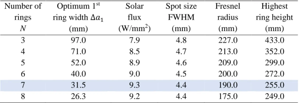
In Fig. 4 is shown the solar flux as a function of the ring width for 3 to 8 rings. The RAC with seven rings had the highest solar flux of 9.3 W/mm2, while the RAC with three rings had the lowest flux of 7.9 W/mm2. The increase in the number of rings beyond the seventh ring was disadvantageous for the solar flux enhancement.
Table 4 shows the numerically calculated solar flux and focal spot size for an optimal ∆𝑎1 for different number of rings. From one hand, the Fresnel lens associated with a small number of rings (3 rings) had a large radius, and the innermost ring had the highest ring height. On the other hand, as the number of rings increased, the radius of the Fresnel lens decreased, resulting in the reduction of the RACs height. The seven rings setup were finally chosen for the single RAC solar furnace.
Table 4 - Optimization of the RAC solar furnace unit parameters for 0.5 m radius RAC.
Number of rings N Optimum 1st ring width ∆𝑎1 (mm) Solar flux (W/mm2) Spot size FWHM (mm) Fresnel radius (mm) Highest ring height (mm) 3 97.0 7.9 4.8 227.0 433.0 4 71.0 8.5 4.7 213.0 352.0 5 52.0 8.9 4.6 209.0 299.0 6 40.0 9.0 4.5 200.0 272.0 7 31.5 9.3 4.4 190.0 255.0 8 26.3 9.2 4.4 175.0 249.0
2.3 – Temperature analysis of the MSSF parabolic mirror and the single RAC solar furnaces.
ZEMAX® non-sequential ray-trace code for solar flux calculation and ANSYS® finite element
analysis for temperature calculation were both used for evaluating the performance of each solar furnace. This method allows thermal-optical calculation that deal with complex geometric shape and boundary conditions, enabling the approximation of variables in a volume or surface element that changed across the element. Thus, the variation of the field variables can be specified to increase degrees of approximations (An et al., 2005) (Li et al., 2015) (Rinker et al., 2018) (Khalil et al., 2019).
The PROMES-CNRS MSSF parabolic mirror of 1 m radius, 0.85 m focal length and 59% combined reflectance (heliostat + parabolic mirror) has the highest solar flux compared to other existing solar furnaces (Table 1). Therefore, the temperature of this solar furnace was firstly numerically analyzed, serving as a reference for the temperature analysis of the single RAC. The typical solar irradiance of 1000 W/m2 in Odeillo, France, was taken into the consideration
in the analysis.
A squared black body (emissivity ε = 1) detector of 20 × 20 mm2 area with 101 × 101 pixels
was used to calculate the solar flux at the focal spot of the MSSF parabolic mirror in ZEMAX®. 16.2 W/mm2 peak solar flux was calculated, which is in concordance with the measured solar flux (PROCÉDÉS, 2018). The data was then imported to ANSYS® workbench through “External data” component and loaded as heat flux source.
12
ANSYS® 2019 finite element analysis was used to analyze the temperature achieved by a graphite disk receiver of 20 mm diameter and 5 mm thickness at the focus of the MSSF parabolic mirror. Graphite with 2250 kg/m3 constant density, 24 W/m.K thermal conductivity and 709 J/Kg.K specific heat was chosen from ANSYS® internal material library. The disk receiver was divided by tetrahedrons meshing method with sizing element of 0.4 mm. It contains approximately 1600 elements, which is enough for FEA calculations (Ozakin and Kaya, 2019). The boundary conditions of convection were applied onto the disk surfaces with heat transfer coefficient of 5×10⁻⁶ W/mm2/K, representing natural stagnant air convection. The radiation exchange between surfaces in ANSYS® was restricted by a gray-diffuse surface. The emissivity for graphite disk surfaces was considered as ε = 0.85, which is an average emissivity of graphite at working temperature above 3000 K (Kostanovskii et al., 2005). 295.15 K ambient temperature was considered. The MSSF with 3.14 m2 collection area had a peak solar flux of 16.2 W/mm2 calculated by ZEMAX®. It is equivalent to a maximum temperature of 3827 K in ANSYS® calculations (Fig. 5 a), which is nearly the same as the reported value of 3800 K (PROCÉDÉS, 2018). The same analysis method was then used for the single RAC with the same collection area of 3.14 m2, attaining a 16.0 W/mm2 in ZEMAX®, resulting in a maximum temperature of 3778 K (Fig. 5 b). Both solar furnaces presented a nearly similar maximum to minimum temperature range by the same receiver, as shown in Fig. 5.
Fig. 5. Temperature at the focal spot of the (a) the PROMES-CNRS MSSF parabolic mirror and (b) the single RAC solar furnace with the same collection area of 3.14 m2.
3 – Numerical optimization of the 3D RAC solar furnace
In Fig. 6 is shown the proposed 3D RAC solar furnace, which consists of five RAC units focusing the incoming solar light into a common focal spot. These RACs formed a compact box-shaped solar furnace with an opening at the rear side for an easy access to a focal spot in the center. The concentrating process is shown in Fig. 7. The main RAC receives the incoming solar light reflected by the heliostat, while the four lateral RACs receive the reflected sunlight firstly by the heliostat and then by the four plane folding mirrors of 95% reflectivity.
Single RAC
b)
MSSF parabolic mirror
13
Fig. 6. 3D RAC solar furnace composed of five identical seven-ring RACs and four folding mirrors.
Fig. 7. Schematics of the cross-sectional view of the 3D RAC solar furnace with solar rays being concentrated to a common spot.
3.1 – Heat load analysis of the 3D RAC, the MSSF parabolic mirror and the Fresnel lens solar furnaces.
The heat load analysis of the solar furnaces was conducted with a 15 mm × 15 mm × 15 mm volume detector in ZEMAX®. To ensure an accurate comparison with the performance of the 3.14 m2 (1 m radius) MSSF parabolic mirror, each RAC unit had 0.447 m radius, corresponding to 0.628 m2 collection area; therefore, a combined 3.14 m2 collection area was achieved for the five RAC units mounted together to form the 3D RAC solar furnace. 59% reflectivity was assumed for all the rings and 95% reflectivity for the folding mirrors. The heat load analysis of an optimal non-imaging PMMA Fresnel lens, with the same collection area and 0.5 m focal length, was also numerically calculated.
Main RAC solar furnace unit (59% reflectivity) Plane folding mirror (95% reflectivity) Small Fresnel Lens Plane folding mirror
Side RAC solar furnace unit
(59% reflectivity)
Mechanical support
Main RAC solar furnace unit
Plane folding mirror (95% reflectivity) Focal spot Side RAC furnace unit Fresnel lens Mechanical support
14
The heat load distributions and the FWHM dimensions of the focal spots of the 3D RAC, the MSSF parabolic mirror and the Fresnel lens solar furnaces are shown in Fig. 8.
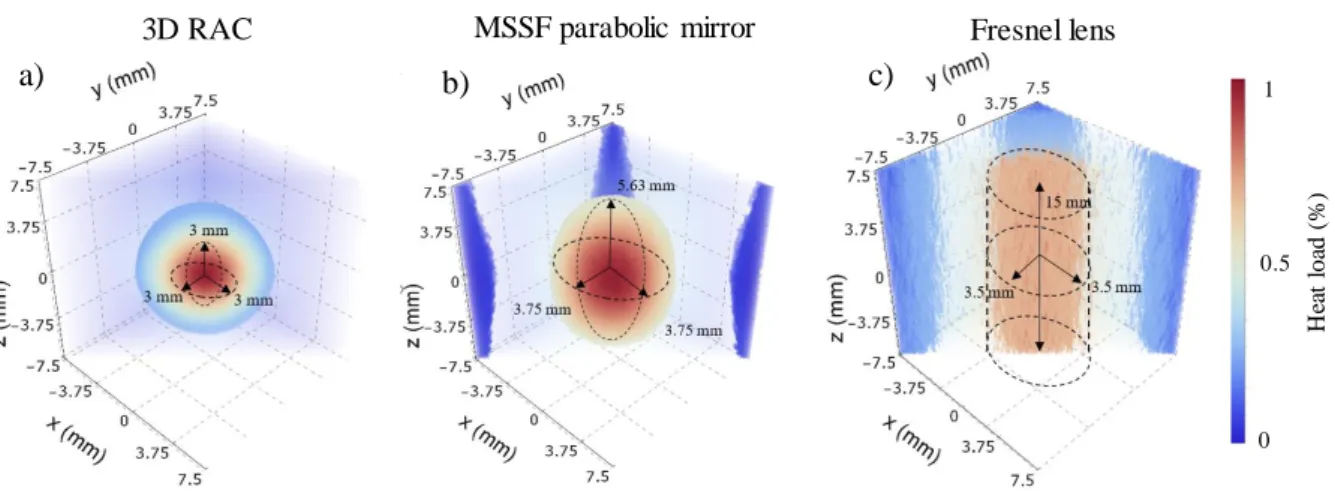
Fig. 8. Cross-sectional view of the heat load distribution at the focal spot of (a) the 3D RAC, (b) the MSSF parabolic mirror and (c) the Fresnel lens solar furnaces.
Due to the short focal length of 0.447 m for each 3D RAC unit, a considerably small spherical focal volume of 3 mm × 3 mm × 3 mm (27 mm3) was obtained, as compared to that of the MSSF parabolic mirror, which obtained a large ellipsoidal-shape focal volume of 3.75 mm × 3.75 mm × 5.63 mm (41.45 mm3). The Fresnel lens presented a significantly large cylindrical focal volume of 3.5 mm × 3.5 mm × 15 mm (577 mm3).
The unique combination of the five RAC’s units ensured therefore a considerably enhanced solar flux as compared to that of the conventional parabolic mirror solar furnace. This also may open a door for the high flux solar pumping of laser media, such as Alexandrite that requires very high pumping flux within a small volume (Kerridge-Johns and Damzen, 2018).
3.2 – Improvement of solar concentration ratio by the 3D RAC solar furnace and its consequent influence on both thermal and optical efficiencies
3.2.1 – Improvement of solar concentration ratio by the 3D RAC furnace
The concentration ratio C is defined by the input aperture area of the focusing collector over the receiver area (C = Sconcentrator /Sreceiver) (Rabl, 1985). By using the edge-ray principle
(Welford and Winston, 1978) and assuming θa = 0.265° Sun-Earth acceptance half-angle
subtended by the Sun (Rabl, 1985), the maximum radius of a spherical receiver (rsphere) at the
focus of a parabolic mirror can be determined by the parabola’s radial aperture (rparabola) and its
rim angle (Φ) (Romero and Steinfeld, 2012) (Goswami, 2015), as indicated by equation 9 and
Fig. 9a.
𝒓𝒔𝒑𝒉𝒆𝒓𝒆 = 𝒓𝒑𝒂𝒓𝒂𝒃𝒐𝒍𝒂 𝒔𝒊𝒏 𝜽𝒂
𝒔𝒊𝒏 𝜱 ( 9 )
The maximum solar concentration ratio for an ideal perfectly specular 3D paraboloid rim angle aligned to the Sun, is given by equation 10 (Rabl, 1985).
3D RAC MSSF parabolic mirror Fresnel lens
1 0 0.5 H ea t l oa d (%) a) b) c)
15 𝒑𝒂𝒓𝒂𝒃𝒐𝒍𝒂 = 𝑺𝒑𝒂𝒓𝒂𝒃𝒐𝒍𝒂 𝑺𝒔𝒑𝒉𝒆𝒓𝒆 = 𝝅 𝒓𝒑𝒂𝒓𝒂𝒃𝒐𝒍𝒂𝟐 𝟒 𝝅 𝒓𝒔𝒑𝒉𝒆𝒓𝒆𝟐 = 𝒔𝒊𝒏𝟐𝜱 𝟒 𝒔𝒊𝒏𝟐 𝜽 𝒂 ( 10 )
Fig. 9. Solar concentration schemes of a) the parabolic mirror and b) the 3D RAC solar furnaces, both with the same collection
area S; SRAC1, SRAC2, SRAC3, and SRAC4, SRAC5 (not seen in Fig.9) are the collection areas of each single RAC; rRAC is the radius
of a single RAC; r’RAC is the inner radius of the outmost ring of the RAC; rsphere and r’sphere are the radius of the receiver
spheres of the parabolic mirror and the 3D RAC solar furnaces, respectively ; Φ and Φ’ are the rim angles of the parabolic mirror and the 3D RAC solar furnaces, respectively; θa is the Sun-Earth acceptance half-angle.
The 3D RAC furnace total collection area (S3DRAC) is given by the combination of the five
single RACs collection area (SRACi), as shown in Fig. 9b and equation 11.
𝑺𝟑𝑫 𝑨 = ∑𝟓𝒊=𝟏𝑺 𝑨 𝒊 ( 11 )
Since the 3D RAC furnace is composed of five single RACs with the same aperture and focal length, by the edge-ray principle, the radius of the spherical receiver of the 3D RAC (r’sphere)
can be determined by the inner radius of the outmost ring of a RAC (r’RAC), its rim angle (Φ’)
and the Sun-Earth acceptance half-angle (θa = 0.265°), as shown in equation 12:
𝒓′𝒔𝒑𝒉𝒆𝒓𝒆 = 𝒓′ 𝑨 𝒊 𝒔𝒊𝒏 𝜽𝒂
𝒔𝒊𝒏 𝜱′ ( 12 )
From equations 11 and 12, the concentration ratio of the 3D RAC can then be calculated by:
𝟑𝑫 𝑨 = 𝑺𝟑𝑫 𝑨 𝑺′ 𝒔𝒑𝒉𝒆𝒓𝒆 = ∑𝟓𝒊=𝟏𝑺 𝑨 𝒊 𝟒 𝝅 𝒓′𝒔𝒑𝒉𝒆𝒓𝒆𝟐 = ∑𝟓𝒊=𝟏𝝅 𝒓 𝑨 𝒊𝟐 𝒔𝒊𝒏 𝟐𝜱′ 𝟒 𝝅 𝒓′ 𝑨 𝟐 𝒔𝒊𝒏𝟐 𝜽𝒂 = 𝟓 𝟒 𝒓 𝑨 𝟐 𝒔𝒊𝒏 𝟐𝜱′ 𝒓′ 𝑨 𝟐 𝒔𝒊𝒏𝟐 𝜽𝒂 ( 13 ) 𝑜 ′ 𝑅 𝐶 1 𝑅 𝐶 𝑅 𝐶 𝑅 𝐶 = 𝑅 𝐶 𝑖 𝑖=1 a) b) lane folding mirror ( reflectivity 𝑜 ′ ℎ ℎ lane folding mirror ( reflectivity ′𝑅 𝐶 𝑅 𝐶
16
The MSSF parabolic mirror with rparabola = 1000 mm has 60° rim angle and 850 mm focal
distance. For the same collection area (S = 3.14 m2), each RAC has r
RAC = 447 mm,
r’RAC = 420 mm, 447 mm focal distance and 43° rim angle. By using the edge-ray principle, the
spherical receiver surface areas of 358.42 mm2 (rsphere = 5.34 mm) and 101.47 mm2 (r’sphere =
2.84 mm) were calculated for the MSSF parabolic mirror and the 3D RAC furnaces, respectively. The concentration ratios of 8765 for the MSSF parabolic mirror and 30962 for the 3D RAC solar furnace were finally obtained, respectively, as summarized by Table 5.
Table 5 – Comparison of the MSSF parabolic mirror concentration ratio with that of the 3D RAC furnace
3D RAC furnace MSSF parabolic mirror
Collection area (m2) 3.14 3.14
Sphere radius (mm) 2.84 5.34
Concentration ratio 30962 8765
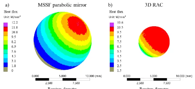
Fig. 10 shows the incident solar flux distribution onto the spherical receivers of both the MSSF parabolic mirror (rsphere = 5.34 mm) and the 3D RAC (r’sphere = 2.84 mm) solar furnaces. The
large receiver surface of the MSSF parabolic mirror has one single light spot with high flux at its top, while little or no presence of light irradiance at its bottom, as shown in Fig. 10a. For the small 3D RAC receiver, the majority of its surface area is irradiated more uniformly than that of the MSSF parabolic mirror by high flux solar power, as shown in Fig. 10b.
Fig. 10. The solar flux distribution profile on the surface of the spherical receivers from a) the MSSF parabolic mirror and b) the 3D RAC solar furnace.
3.2.2 – Improvement of solar thermal efficiency by the 3D RAC furnace
An ideal solar thermal energy conversion efficiency is given by equation 14 (Romero and Steinfeld, 2012) (Steinfeld, 2019): 𝜼 𝑺𝒐𝒍𝒂𝒓 𝒕𝒉𝒆𝒓𝒎𝒂𝒍, 𝒊𝒅𝒆𝒂𝒍= [𝟏 − (𝝈𝑻𝒉𝟒 𝑰 )] [𝟏 − ( 𝑻𝟎 𝑻𝒉)] ( 14 )
17
where I is the solar radiation (1000 W/mm2), σ is the Stefan-Boltzmann constant, Th isthe
receivers temperature and T0 is the ambient temperature. Increasing concentration ratio is
advantageous to attain higher temperatures and reduce the re-radiation losses from a smaller solar receiver’s surface, but at the expense of more precise and costly optics, as in the case of the 3D RAC furnace. Fig. 11 shows the thermal efficiency tendency versus the variation of the receiver’s temperature for the two types of furnaces. The MSSF parabolic mirror with 8765 concentration ratio had an equivalent 3530 K stagnant temperature. In contrast, the 3D RAC furnace with a smaller collector surface area attained a much higher concentration ratio of 30962, attaining 4833 K stagnant temperature. However, in practice, when considering convective and conductive losses in addition to radioactive losses, as well as the inherent optical losses of the solar concentrating system, the efficiency presents a much lower value.
Fig. 11. Thermal efficiency of the 3D RAC solar furnace, the parabolic mirror and their respective concentration ratios.
3.2.3 – Improvement in optical efficiency by the 3D RAC solar furnace
The optical efficiency is defined as the ratio between the absorbed solar powerby a receiver and the incoming solar power of a solar collector. Fig. 12 shows the comparison of the optical efficiencies of the MSSF parabolic mirror and 3D RAC furnace, for various spherical receiver sizes. For the MSSF parabolic mirror, 37.8% optical efficiency was numerically achieved for the 2rsphere = 10.68 mm diameter spherical receiver, while less optical efficiency of 29.5% was
numerically attained for the 2r’sphere = 5.68 mm diameter spherical receiver of the 3D RAC.
However, for receiver spheres of same diameter, the 3D RAC furnace offered a significantly higher optical efficiency compared to that of the MSSF parabolic mirror. For example, for the 10.68 mm diameter, 51.0% optical efficiency was numerically achieved by the 3D RAC, which is 1.35 times more than that of the parabolic mirror. For receiver sphere larger than 15 mm diameter, the 3D RAC suffers from a slight decrease in optical efficiency.
C=8765
18
Fig. 12. Optical efficiency comparisons between the 3D RAC and the MSSF parabolic mirror at different receiver diameters.
Finally, the product of the thermal efficiencies in Fig. 11 and the optical efficiencies in Fig. 12 can result in the final absorption efficiencies by the receiver spheres for both the 3D RAC solar furnace and the MSSF parabolic mirror, respectively, as given by equation 15:
𝜼 𝑺𝒐𝒍𝒂𝒓 𝒕𝒉𝒆𝒓𝒎𝒂𝒍= 𝜼 𝒐𝒑𝒕𝒊𝒄𝒂𝒍[𝟏 − (𝝈𝑻𝒉𝟒
𝑰 )] [𝟏 − ( 𝑻𝟎
𝑻𝒉)] ( 15 )
3.3 – Temperature performance analysis of the solar furnaces
Since the focused solar light at the focal spot of the 3D RAC are from five different directions (Fig. 7), the use of the disk receiver is not suitable to analyze the temperature. Therefore, a spherical receiver was used to analyze the temperature for both the MSSF parabolic mirror and the 3D RAC solar furnaces.
In ZEMAX®, a stereolithographic (STL) sphere of 2.84 mm radius with a total of 5624 superficial pixels was firstly used to replace the disk receiver at the focus of the MSSF parabolic mirror. The center of the sphere coincided with the center of the focal spot, as shown in Fig. 13a. The maximum temperature of 3582K, the minimum temperature of 2371 K and the average temperature of 2841 K were numerically achieved, as shown in Fig. 13.
37.8% 29.5%
5.68 10.68
19
Fig. 13. a) Spherical graphite receiver at the focal spot. b) Top view and c) cross-sectional view of the temperature distribution at the focal spot of the MSSF parabolic mirror.
A 2.84 mm radius spherical STL detector was then used for the temperature analysis of the 3D RAC furnace. The maximum temperature of 3756K, the minimum temperature of 3344K and the average temperature of 3632 K were numerically achieved, as shown in Fig. 14.
Fig. 14. a) Spherical graphite receiver at the focal spot. b) Top view and c) cross-sectional view of the temperature distribution at the focal spot of the 3D RAC furnace.
The collection area of the solar furnace and the size of the receiver are critical factors to determine the amount of solar radiation reaching the focal spot. The 3D RAC, the parabolic mirrors and the Fresnel lens furnaces were analyzed for the temperature comparison at their focal spot. Fig. 15 shows the maximum attainable temperature for collection area up to 100 m2. 5.68 mm, 10.68 mm, 15mm and 20 mm diameter spherical receivers were used.
20
For collection areas smaller than 3.14 m2, the MSSF offered the highest temperature and the 3D RAC furnace provided a slightly reduced temperature, while the Fresnel lens produced the lowest temperature. However, for the 5.68 mm diameter receiver, the 3D RAC exceeded the maximum temperature of the MSSF parabolic mirror, when the collection area was larger than 3.14 m2. For collection areas varying from 3.14 m2 to 100 m2, 1.1 times gradual enhancement
in maximum attainable temperature were numerically calculated. The maximum temperature of the 3D RAC furnace also increased faster than that of the MSSF parabolic mirror for all receivers, as shown in Fig. 15.
Fig. 15. Maximum temperature of 3D RAC, parabolic mirror and Fresnel lens as a function of the collection area for receiver diameter of a) 5.68 mm, b) 10.68 mm, c)15 mm and d) 20 mm.
Due to its short focal length, the 3D RAC furnace had the advantage of achieving effective solar concentration within a smaller focal spot and only a small portion of the focused rays missed the smaller diameter receiver, when compared to that of the parabolic mirror with an enlarged focal spot. For large collection area, the 3D RAC had an evident tendency for attaining higher temperature than that of the parabolic mirror. Moreover, a multiple side heating together with less heat dissipation from the small focal spot of the 3D RAC furnace also enabled a higher temperature than that of the parabolic mirror.
Maximum temperature
a)
b)
c)
d)
3.14 3.14
21
The Fresnel lens presented about 45% reduction in the maximum temperature performance, as compared to the above-mentioned parabolic mirror and 3D RAC schemes. No significant variation in temperature was attained neither with more collection area nor with larger receiver. Besides the importance of the maximum temperature, average and minimum temperatures are also vital parameters to characterize the working temperature capacity of a solar furnace. Fig. 16 shows the influence of the receiver size and the collection area on average and minimum temperatures for each type of solar furnace. The 3D RAC furnace presented advantages in average and minimum temperatures for all collection areas.
Fig. 16. Average and minimum temperature of 3D RAC, MSSF parabolic mirror and Fresnel lens as a function of the collection area for receiver diameter of a) 5.68 mm, b) 10.68 mm, c) 15mm and d) 20 mm.
With the 5.68 mm diameter receiver and the collection area varying from 3.14 m2 to 100 m2, the average and minimum temperatures of the 3D RAC furnace were significantly improved by 870 K and 1140 K, respectively, as compared to that of the parabolic mirror, as shown in Fig. 16a. Even for a large diameter receiver, the superiority of the 3D RAC furnace in both average and minimum temperature operation remained. With the 20 mm diameter receiver and 100 m2 collection area, for example, the 3D RAC furnace achieved about 870 K average temperature and 1140 K minimum temperature enhancements, respectively, over that of the
Average and minimum temperature
a)
b)
c)
d)
3.14 3.14 3.14 3.14 Average temperature: Minimum temperature:22
parabolic mirror, as shown in Fig. 16d. The Fresnel lens presented significantly reduced average and minimum temperature values among these three types of solar furnaces.
3.4 – Influence of convection coefficient on the temperature performances of both the 3D RAC solar furnace and the MSSF parabolic mirror
The temperature performances of both the 3D RAC and the parabolic mirror solar furnaces depend strongly on the convection coefficient. ANSYS simulation tool was used to analyze this dependency. For 5×10⁻⁶ W/mm2/K convection coefficient, corresponding to the stagnant air situation in the previous sections, maximum, average and minimum temperatures of 3756 K, 3632 K and 3344 K, respectively, were numerically calculated for the 3D RAC furnace with 5.86 mm diameter receiver sphere; while maximum, average and minimum temperatures of 3582 K, 2841 K and 2371 K, respectively, were numerically calculated for the parabolic mirror furnace with 10.68 mm diameter receiver sphere. Therefore, 4.6%, 21.8% and 29.1% more maximum, average and minimum temperature, respectively, were obtained by the 3D RAC furnace. With the increase in convection coefficient, the advantage of the temperature performance of the 3D RAC solar furnace became more evident. For 1.2×10⁻³ W/mm2/K convection coefficient, maximum, average and minimum temperatures of 3321 K, 3182 K, 2865 K, respectively, were calculated for the 3D RAC furnace and 3014 K, 2137 K, 1580 K, respectively, for the parabolic mirror solar furnace. The receiver sphere with large surface area of the MSSF parabolic mirror resulted in more convection losses than that by the receiver sphere with small surface area of the 3D RAC furnace. The 3D RAC solar furnace produced nearly 9.2%, 32.8% and 44.9% more maximum, average, minimum temperature, respectively, than that by the MSSF parabolic mirror scheme, indicating that there were more thermal losses in the parabolic mirror scheme.
Fig. 17. Influence of convection coefficient on the temperature performances of both the 3D RAC solar furnace and the MSSF parabolic mirror.
23
3.5 – Tracking error analysis of the 3D RAC and the parabolic mirror solar furnaces
Tracking error causes the change of the focal spot from the optimal position, resulting in a substantial change of efficiency. In Fig. 17a is shown the efficiency loss of the spherical receiver of 15 mm diameter as function of tracking error in altitude and azimuth directions for MSSF parabolic mirror and 3D RAC solar furnace.
Fig. 18. (a) The absorbed energy by black body detector with the tracking error in altitude and azimuth directions. (b) The heat load distributions of the 3D RAC (1)(2)(3)(4)(5) and the MSSF parabolic mirror (1’)(2’)(3’)(4’)(5’).
At 0.25° altitude and azimuthal tracking errors, about 11% and 42% loss were obtained for 3D RAC and MSSF parabolic mirror, respectively. However, at 0.50° on only one of the axes, a 26% and 68% power loss was obtained for 3D RAC and MSSF parabolic mirror, respectively. At the extreme case of tracking error by 0.50° on both axes, the efficiency was nearly extinguished for the MSSF parabolic mirror and a 60% loss was obtained for 3D RAC. In summary, the 3D RAC furnace had a generally better tracking error performance as compared to the parabolic mirror furnace. Fig. 17b shows the tracking error with heat load efficiency distribution at the focal spot by the 8 mm × 8 mm × 8 mm detector. For small tracking errors,
0% 0.0º, 0.0º E ffi c ie n c y (% ) 0% 3 D R A C M S S F P a ra b o li c m ir ro r 0.25º, 0.0º 0.25º, 0.25º 0.50º, 0.0º 0.50º, 0.25º 0.50º, 0.50º
Tracking error (azimuthº, altitudeº)
(1) (2) (3) (4) (5) (6) (1’ (2’ (3’ (4’ ( ’ (6’ 0 100 50 0 100 50 H e a t lo a d e ff ic ie n c y ( % ) (1) (1’) (a) (b) -26% -26% -11% -4% -4% -60% -36% -36% -42% -22% -22% -78% -78% -68% -68% -92% (2) (2’) (3) (3’) (4’) (4) (5) (5’) (6) (6’)
24
the 3D RAC produced an enhanced heat load distribution at the center of the detector, as compared to that of the parabolic mirror furnace.
4 – Conclusions
Analytical and numerical models were firstly used to optimize the single RAC solar furnace unit parameters. The single RAC, with seven ring-arrays and a small Fresnel lens at the center, provided nearly the same temperature range as that of the 3.14 m2 MSSF parabolic mirror from
PROMES-CNRS. The 3D RAC solar furnace, consisting of five RAC furnace units, was then proposed and numerically optimized in ZEMAX® software. It formed a compact box-shaped solar furnace with an opening at the rear side for an easy access to the common focal spot at the center. By adopting the edge-ray principle, 3.53 times higher concentration ratio was calculated for the 3D RAC furnace, as compared to that of the parabolic mirror, leading to considerably improved thermal and optical efficiencies. The temperature performance of the 3D RAC and its dependency on both the receiver size and collection area were then numerically evaluated in ANSYS® software and compared to that of the MSSF with same collection area. For the 6.5 mm diameter receiver, the 3D RAC exceeded the maximum temperature of the MSSF parabolic mirror for the collection area larger than 3.14 m2. For large collection areas varying from 3.14 m2 to 100 m2, 1.1 times gradual enhancement in the maximum attainable temperature was numerically calculated. With the increase of the collection area, the maximum temperature of the 3D RAC furnace also increased faster than that of the MSSF parabolic mirror for all receivers. For a large size receiver (20 mm diameter for example), 870 K and 1140 K enhancements in average and minimum temperatures, respectively, in relation to that with MSSF, were numerically obtained. This shows the superiority of the 3D RAC, especially for achieving both average and minimum attainable temperatures. In addition, the 3D RAC solar furnace presented better temperature performance with convection loss and an overall enhanced tracking error compensation capacity, as compared to that of the MSSF.
Funding Information Financial support of the strategic project (UID/FIS/00068/2019) of the
Science and Technology Foundation of Portuguese Ministry of Science, Technology and Higher Education (FCT - MCTES) is acknowledged.
Acknowledgment The FCT-MCTES fellowship grants PD/BD/142827/2018, PD/BD/128267/2016, SFRH/BPD/125116/2016, of D. Garcia, B. D. Tibúrcio and C. R. Vistas, respectively, and the Contract CEECIND/03081/2017 of J. Almeida are acknowledged.
25
References
A. Gomes, M., 1899. The Pyreheliophoro, in: INPI (Ed.). France.
Agrafiotis, C., von Storch, H., Roeb, M., Sattler, C., 2014. Solar thermal reforming of methane feedstocks for hydrogen and syngas production-A review. Renew Sust Energ Rev 29, 656-682. Ahmed, F.E., Hashaikeh, R., Hilal, N., 2019. Solar powered desalination - Technology, energy and future outlook. Desalination 453, 54-76.
Almeida, J., Liang, D., Vistas, C.R., Guillot, E., 2015. Highly efficient end-side-pumped Nd:YAG solar laser by a heliostat-parabolic mirror system. Appl. Opt. 54(8), 1970-1977. An, W., Ruan, L.M., Qi, H., Liu, L.H., 2005. Finite element method for radiative heat transfer in absorbing and anisotropic scattering media. J. Quant. Spectrosc. Radiat. Transf. 96(3-4), 409-422.
ASTM Standard G173-03, 2012. Standard Tables for Reference Solar Spectral Irradiances: Direct Normal, and Hemispherical on 37º Tilted Surface.
Bellos, E., Tzivanidis, C., 2019. Alternative designs of parabolic trough solar collectors. Progress in Energy and Combustion Science 71, 81-117.
Camacho-Lopez, T., 2019. National Solar Thermal Test Facility. https://energy.sandia.gov/energy/renewable-energy/solar-energy/csp-2/nsttf/.
Datas, A., Ramos, A., Marti, A., del Canizo, C., Luque, A., 2016. Ultra high temperature latent heat energy storage and thermophotovoltaic energy conversion. Energy 107, 542-549.
Fend, T., Hoffschmidt, B., Pitz-Paal, R., Reutter, O., Rietbrock, P., 2004. Porous materials as open volumetric solar receivers: Experimental determination of thermophysical and heat transfer properties. Energy 29(5-6), 823-833.
Fernandez-Gonzalez, D., Ruiz-Bustinza, I., Gonzalez-Gasca, C., Noval, J.P., Mochon-Castanos, J., Sancho-Gorostiaga, J., Verdeja, L.F., 2018. Concentrated solar energy applications in materials science and metallurgy. Sol. Energy 170, 520-540.
Funken, K.H., Becker, M., 2001. Solar chemical engineering and solar materials research into the 21st century. Renewable Energy 24(3-4), 469-474.
Goswami, D.Y., 2015. Principles of solar engineering. CRC Press, Boca Raton FL.
Haueter, P., Seitz, T., Steinfeld, A., 1999. A new high-flux solar furnace for high-temperature thermochemical research. Journal of Solar Energy Engineering-Transactions of the Asme 121(1), 77-80.
Hussain, M.I., Menezo, C., Kim, J.T., 2018. Advances in solar thermal harvesting technology based on surface solar absorption collectors: A review. Sol. Energy Mater. Sol. Cells 187, 123-139.
Islam, M.T., Huda, N., Abdullah, A.B., Saidur, R., 2018. A comprehensive review of state-of-the-art concentrating solar power (CSP) technologies: Current status and research trends. Renew Sust Energ Rev 91, 987-1018.
Kalogirou, S.A., 2004. Solar thermal collectors and applications. Progress in Energy and Combustion Science 30(3), 231-295.
Kasaeian, A., Tabasi, S., Ghaderian, J., Yousefi, H., 2018. A review on parabolic trough/Fresnel based photovoltaic thermal systems. Renew Sust Energ Rev 91, 193-204. Kerridge-Johns, W.R., Damzen, M.J., 2018. Temperature effects on tunable cw Alexandrite lasers under diode end-pumping. Optics Express 26(6), 7771-7785.
Khalil, I., Pratt, Q., Spitler, C., Codd, D., 2019. Modeling a thermoplate conical heat exchanger in a point focus solar thermal collector. International Journal of Heat and Mass Transfer 130, 1-8.
26
Kostanovskii, A.V., Zeodinov, M.G., Kostanovskaya, M.E., 2005. The determination of thermal conductivity and emissivity of graphite at high temperatures. High Temp. 43(5), 793-795.
Li, B., Oliveira, F.A.C., Rodriguez, J., Fernandes, J.C., Rosa, L.G., 2015. Numerical and experimental study on improving temperature uniformity of solar furnaces for materials processing. Sol. Energy 115, 95-108.
Liang, D.W., Almeida, J., Vistas, C.R., Guillot, E., 2017. Solar-pumped Nd:YAG laser with 31.5 W/m(2) multimode and 7.9 W/m(2) TEM00-mode collection efficiencies. Sol. Energy Mater. Sol. Cells 159, 435-439.
Liu, G.H., Xu, J.L., Wang, K.Y., 2017. Solar water evaporation by black photothermal sheets. Nano Energy 41, 269-284.
Lovegrove, K., Burgess, G., Pye, J., 2011. A new 500 m(2) paraboloidal dish solar concentrator. Sol. Energy 85(4), 620-626.
Matos, R., Liang, D., Almeida, J., Tiburcio, B.D., Vistas, C.R., 2018. High-efficiency solar laser pumping by a modified ring-array concentrator. Optics Communications 420, 6-13. Meinel, A.B., 1979. Applied solar energy. an introduction. Addison-Wesley, Reading.
Mouzouris, M., Brooks, M.J., 2009. Nonimaging solar thermal collector for high temperature terrestrial and space applications, SPIE Optical Engineering and Applications. SPIE, p. 12. Ozakin, A.N., Kaya, F., 2019. Effect on the exergy of the PVT system of fins added to an air-cooled channel: A study on temperature and air velocity with ANSYS Fluent. Sol. Energy 184, 561-569.
Prieto, A., Knaack, U., Auer, T., Klein, T., 2019. COOLFACADE: State-of-the-art review and evaluation of solar cooling technologies on their potential for facade integration. Renew Sust Energ Rev 101, 395-414.
PROCÉDÉS, M.E.É.S.U., 2018. MSSF horizontal - PROMES.
https://www.promes.cnrs.fr/index.php?page=mssf-horizontal. (Accessed 7/3/2019 2019). PROCÉDÉS, M.E.É.S.U., 2019. Mega Watt Solar Furnace - PROMES. https://www.promes.cnrs.fr/index.php?page=mega-watt-solar-furnace. (Accessed 7/3/2019 2019).
PSA-CIEMAT, 2009. BIANUUAL REPORT 2008-2009. Rabl, A., 1985. Active solar collectors and their applications.
Reinalter, W., Ulmer, S., Heller, P., Rauch, T., Gineste, J.M., Ferriere, A., Nepveu, F., 2008. Detailed performance analysis of a 10 kW dish/Stirling system. Journal of Solar Energy Engineering-Transactions of the Asme 130(1).
Rinker, G., Solomon, L., Qiu, S.G., 2018. Optimal placement of radiation shields in the displacer of a Stirling engine. Applied Thermal Engineering 144, 65-70.
Romero, M., Steinfeld, A., 2012. Concentrating solar thermal power and thermochemical fuels. Energy Environ. Sci. 5(11), 9234-9245.
Steinfeld, A., 2019. Concentrated solar energy - the path for efficient thermal conversion to power and fuels. Sci. Bull. 64(8), 485-486.
Tiburcio, B.D., Liang, D., Almeida, J., Matos, R., Vistas, C.R., 2018. Improving solar-pumped laser efficiency by a ring-array concentrator. Journal of Photonics for Energy 8(1).
Trombe, F., Foex, M., 1957. The Production of Cold by Means of Solar Radiation. Sol. Energy 1(1), 51-52.
Vasylyev, V.P.T., Oleg G., 2003. Expected Optical Performances of Novel Type Multi-element High-heat Solar Concentrators. Conference Proceedings.
Welford, W.T., Winston, R., 1978. The optics of nonimaging concentrators : light and solar energy. Academic Press, New York; London.
Winston, R., 1974. Principles of Solar Concentrators of a Novel Design. Sol. Energy 16(2), 89-95.
27
Xie, W.T., Dai, Y.J., Wang, R.Z., Sumathy, K., 2011. Concentrated solar energy applications using Fresnel lenses: A review. Renew Sust Energ Rev 15(6), 2588-2606.