CoBlast
TM
industrial process validation
Ana Sofia Azevedo Oliveira
Supervisor: Eduardo Ascenso Pires, PhD
Co-Supervisor: Fernando Jorge Monteiro, PhD
Integrated Master in Bioengineering
Master in Biomedical Engineering
ii
iii
iii
The present document is based on the work carried out during a curricular internship at the Portuguese company Ceramed S.A., under the local supervision of Doctor Eduardo Ascenso Pires, chief executive officer of Ceramed, and the scientific supervision of Professor Fernando Jorge Monteiro, professor of the Department of Metallurgical and Materials Engineering of Faculty of Engineering - University of Porto.
iv
v
v
Abstract
Each year, a critical number of people is affected by healthcare-associated infections due to implantation of total hip and total knee prostheses and trauma implants. These last have an increased tendency for infection, mainly due to the fact that they are applied to repair complex injuries and open fractures. Infection together with the eventual loosening of an orthopaedic implant explains the limited lifespan of an orthopaedic device.
Research over the years focused on finding the best materials to develop a range of implant coatings with the ability to improve implant binding to the host bone tissue and avoid infection.
Hydroxyapatite based coatings are still one of the most frequently used implant coatings in the field of orthopaedic surgery and trauma, resulting in improved implant ingrowth and a longer lifespan of the prosthesis.
A great number of technologies are currently used to deposit implant coatings. While some of them require high temperatures that can alter coating crystallinity and compromise coating bioactivity, others act under room temperatures to apply coatings with limited thermal stability. Nevertheless coating delamination and cracking are still frequent.
Plasma-spray is the most used and accepted method for Hydroxyapatite coating application. This deposition process frequently affects coating crystallinity due to the high temperatures used in processing. Phase transformations tend to occur, what will enhance the resorption process of coating leading to implant instability.
Therefore, it is urgent for innovative and effective coating technologies, that do not require high temperatures, to reach the market of medical coatings, since those may help to accomplish a combined situation of a coating with both antimicrobial and osteoconductive properties.
It is crucial for the market of medical coatings to understand this urgency and to provide time, attention and investment to research and development of new technologies with industrial applicability. An insightful way of doing this is picking existing technologies with basic principles reported, observed and characteristic proof-of-concept demonstrated and seek their implementation in industrial production.
Ceramed S.A. is a Portuguese company with ten years of history, specialized in medical
devices coatings, which counts on great number of partnerships focused on research and development of new concepts and technologies for the sector. This company comprehends the sector and market needs and is interested in making the industrial validation of an innovative technology for Hydroxyapatite coating application.
vi
vi
CoBlast is a cleaning, roughening, and coating technology that works under room temperature and pressure, with minimal substrate alteration developed by a co-founder of a company named Enbio Limited, which can offer the solution this field is waiting for.
This master thesis contributes to this by providing a Master Validation Plan for CoBlast process and performing the major Validation steps of this new coating technology.
Process validation is a key part of the Quality Management System for medical device manufacturers. It intends to establish by objective evidence that a process consistently produces a result or a product meeting its predetermined specifications.
On the course of this master thesis, the different phases of process validation were carried out. Installation Qualification was successfully accomplished, the objectives proposed for Operational Qualification have been meet, and a study of Performance was developed. Further works should focuses on going where this work had no time to go: process mass flow rate optimization.
Keywords: CoBlast, Medical device coating processes, Process Validation, Bioactive coatings, Hydroxiapatite.
vii
vii
Resumo
Todos os anos, um número significativo de pessoas é afetado por infeções relacionadas com a assistência médica de aplicação de próteses de substituição total de anca e joelho e implantes de traumatologia. Estes apresentam uma tendência superior para a infeção, devido ao facto de serem aplicados para reparar lesões complexas e fraturas expostas. A infeção somada à eventual rejeição do implante ortopédico explica o tempo de vida útil limitado deste tipo de dispositivos.
Ao longo do tempo, a investigação científica tem vindo a focar-se em encontrar os melhores materiais para desenvolver um leque de revestimentos para implantes com a capacidade de melhorar a fixação destes ao tecido ósseo do paciente e evitar infeções.
Os revestimentos baseados em Hidroxiapatite continuam a ser os mais frequentemente aplicados em implantes médicos na área da cirurgia ortopédica e de trauma, resultando numa melhor aceitação do implante e num aumento do seu tempo de vida útil.
Atualmente, um número considerável de tecnologias são usadas na aplicação de revestimentos em implantes. Enquanto algumas utilizam temperaturas altas que podem alterar a cristalinidade do revestimento e comprometer a sua bioatividade, outras atuam à temperatura ambiente de forma a aplicar revestimentos com baixa estabilidade térmica. Apesar disso, a delaminagem e fratura do revestimento continuam a ser frequentes.
A deposição por plasma continua a ser a tecnologia mais bem aceite e utilizada para aplicação de revestimentos de Hydroxiapatite em dispositivos médicos. Este método afeta frequentemente a cristalinidade do revestimento devido às altas temperaturas envolvidas no processo, o que pode levar a uma rápida reabsorção do mesmo provocando instabilidade na zona do implante.
Por este motivo, é urgente que tecnologias inovadoras e eficientes que não necessitem de altas temperaturas cheguem ao mercado dos revestimentos de dispositivos médicos. Estas podem ajudar a atingir o objetivo de combinar num só revestimento tanto características antimicrobianas como osteocondutoras.
É crucial que este mercado entenda esta urgência e aja no sentido do investimento em investigação e desenvolvimento de novas tecnologias com aplicabilidade industrial. Uma forma perspicaz de o fazer, é trabalhar tecnologias promissoras com os seus princípios básicos já reportados e provas de conceito feitas e procurar a sua implementação na produção industrial.
A Ceramed S.A. é uma empresa Portuguesa com dez anos de existência, especializada na aplicação de revestimentos em dispositivos médicos, que conta com um número de parcerias focadas em investigação em desenvolvimento de novos conceitos e tecnologias no sector. A
viii
viii
Ceramed entende as necessidades do mercado e está empenhada em fazer a validação industrial de uma tecnologia inovadora para a aplicação de revestimentos de Hidroxiapatite em dispositivos médicos.
O CoBlast é uma tecnologia que limpa, cria rugosidade e reveste a uma temperatura e pressão ambiente, com mínima alteração do substrato, desenvolvida pelo cofundador da empresa Enbio Limited, que pode oferecer a solução que este sector espera.
Esta tese de mestrado contribui para isto ao fazer um Plano piloto de Validação para o processo de CoBlast e ao concluir os passos chaves dessa Validação de processo.
A Validação de Processos é uma parte chave dos Sistemas de Gestão da Qualidade em empresas de aplicação de revestimentos médicos. O seu intuito é provar com base em evidências objetivas que o processo é capaz de atingir um resultado ou produto de acordo com as suas especificações predeterminadas.
No decorrer desta dissertação de mestrado, as diferentes fases de Validação do Processo foram levadas a cabo. A Qualificação da Instalação foi bem sucedida, os objetivos propostos para a Qualificação Operacional foram cumpridos, e um estudo de Performance do processo foi feito.
Os trabalhos futuros deverão focar-se em fazer a otimização do fluxo de massa do processo.
Palavras-chave: CoBlast, Processos de aplicação de revestimentos em dispositivos médicos, Validação de processo, Revestimentos bioativos, Hidroxiapatite.
ix
ix
Acknowledgements
I would like to thank Dr. Eduardo Ascenso Pires for accepting and welcoming me at Ceramed and allowing me to take part in the company that he created, unique in Portugal. I am sincerely grateful for his supervision, support and knowledge, and foremost, for being an inspiring person, a man who fights for what he believes in.
I would like to express my sincere gratitude to Professor Fernando Jorge Monteiro. There are two moments that I am thankful for in the course of my master thesis planning: the day that I decided to contact Ceramed, and the day that I came to Professor Fernando Jorge Monteiro to ask him to be my supervisor in the Faculty of Engineering. Professor Fernando Jorge Monteiro was flawless in every aspect, an honest and forthright person that I am grateful to have met and have as my supervisor.
In full gratitude I would like to acknowledge all Ceramed, namely all the people that I had the pleasure to work with during this last four months. Because of you, getting up to work everyday was really easy. My special thanks to Ana Duarte, Director of Ceramed, Vânia Miranda, Regulatory Affairs Manager, André Baião, Responsible for Quality Control, Pedro Moura, Responsible for Plasma-Spray and Francisco Vale, Financial Director. From Ceramed affiliated companies, I would like to thank Hugo Araújo from Astrolabe and Luis Pinto and José Manuel Ventura from Altakitin.
I would like to thank Enbio Limited team for advising and helping me whenever I needed. Particularly, I would like to thank John O’Donoghue, Chief Executive Officer at Enbio and inventor of CoBlast technology, Barry Twomey, Vice President of Research and Development, John Collins, Conformity and Compliance Manager and Conor Dunne, PhD researcher at University College Dublin.
I must also acknowledge Faculty of Science and Technology, Universidade Nova de Lisboa (FCT/UNL), represented by Professor João Paulo Borges, for providing the resources and support to perform Scanning electron microscopy, X-ray diffraction and X-ray fluorescence on my samples. My honest thanks to Professor João Paulo Borges and Professor João Pedro Veiga.
Without a doubt, I would like to thank my parents. Not only for the great life I have led thanks to them but also for the moment I am experiencing now, finishing my undergraduate studies. There are really no words for how much I am thankful to them. I would also like to thank to my brother, an influencer that I am pleased to have in my life.
A very special thanks goes out to my Lisbon house mates. I moved four months ago, and I shared a place with three awesome house mates: Vânia Pacheco, Gonçalo de Almeida and
x
x
Ana Carolina Leite. I want their names to be recorded here. With both little and big gestures they managed to make my day better when it wasn’t being that bright, especially because of being far away from my loved ones. You rocked, guys.
I would like to thank my friends, both my childhood and my faculty friends that have always had a smile, two open arms, and a free spirit that keeps me young. I am sure they will celebrate with me this joyful moment.
Last but not least, I would like to thank all of the professors in FEUP that I had the pleasure to have as teachers, for all the lessons and enlightening that made me capable of doing this work today.
xi
xi
“Every great advance in science has issued from a new audacity of imagination.”
xii
xiii xiii
Contents
Abstract... v Resumo ... vii Acknowledgements ... ix Contents ... xiiiList of Figures ... xvii
List of tables ...xix
List of Abbreviations ...xxi
Chapter 1 ... 1 Introduction ... 1 1.1 Motivation ... 1 1.1.1. Ceramed ... 2 1.1.2. Enbio Limited ... 2 1.2 Objective ... 2 1.3 Contributions ... 3 1.4 Document Structure ... 3 Chapter 2 ... 5
Bioactive coating materials ... 5
2.1. Calcium orthophosphates ... 5
Chapter 3 ... 9
Overview of medical device coating processes ... 9
3.1 Abrasive blasting ... 9
3.2 Thermal spraying techniques ... 9
2.2.1. Plasma spray ... 10
2.2.2. Flame spray ... 10
2.2.3. High velocity oxygen fuel (HVOF) ... 11
2.2.4. Electrical arch spray ... 11
3.3 Electrodeposition ... 11
3.4 Sputtering ... 12
3.5 Chemical vapour deposition (CVD) ... 12
3.6 Physical vapour deposition (PVD) ... 13
3.7 Pulsed laser deposition (PLD) ... 13
3.8 Sol-gel immersion technique ... 14
3.9 Sintering ... 14
xiv
xiv
CoBlastTM ... 15
4.1 Invention ... 16
4.2 Deposition conditions and parameters ... 18
4.3 Reviewed Publications ... 20
Chapter 5 ... 27
Process Validation ... 27
5.1 Purpose ... 27
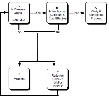
5.1.1. Process Validation Decision ... 27
5.1.2. Statistical Principles ... 29
5.2 Phases of process validation ... 30
5.2.1_Installation Qualification (IQ) ... 31
5.2.2_Operational Qualification (OQ) ... 31
5.2.3_Performance Qualification (PQ) ... 31
5.3 Monitor, Control and Revalidation ... 32
5.4 Regulatory specifications ... 32
Chapter 6 ... 33
CoBlast Validation Plan ... 33
6.1 Raw materials and substrate ... 34
6.2 Equipment ... 35
6.2.1 _Advanced Lathe ... 35
6.2.2 _Powder feeder ... 37
6.2.3 _Vacuum cleaner ... 38
6.2.4 _Blender ... 38
6.3 Static Parameters & Parameters under Evaluation ... 40
6.4 Process requirements ... 42 6.5 Validation Protocol ... 43 6.5.1 _Installation Qualification ... 44 6.5.2 _Operational Qualification ... 44 6.5.3 _Performance Qualification ... 48 Chapter 7 ... 52
CoBlast Process Validation ... 52
7.1 Installation Qualification ... 52
7.1.1CoBlast equipment IQ_ ... 52
7.1.2Blending equipment IQ ... 57
7.1.3 _Result and report of installation qualification... 61
7.2 Operational Qualification ... 61 7.2.1 _Blending OQ ... 61 7.2.2 _Blasting OQ ... 65 7.3 Performance Qualification ... 81 7.3.1 _Monitoring plan ... 85 7.4 Internal procedures ... 86 7.5. Economic Evaluation ... 87 References ... 90 Appendix A ... 96 Calculations ... 96
Raster Offset determination for each nozzle height... 97
Appendix B ... 100
Equipment IQ checklists ... 100
CoBlast equipment IQ checklists ... 101
xv
xv
Result of IQ checklist ... 109
Appendix C ... 110
Production Internal documentation ... 110
Work instructions ... 111
Appendix D ... 114
Raw material Certificates of Compliance ... 114
Ti-6Al-4V compliance certificate ... 115
HA compliance certificates ... 116 Al2O3 compliance certificate ... 118 MCD 180 compliance certificate ... 119 Appendix E ... 120 CNC codes ... 120 SUB STEP A ... 120 SUB STEP B ... 121 SUB STEP C... 124 ADHESION ... 126 SCREW ... 128 Appendix F ... 130
xvi
xvii
xvii
List of Figures
Figure 3.1 – Schematic of a conventional DC arc spray torch with a nozzle ... 10
Figure 3.2 - Typical pulsed laser deposition (PLD) system ... 13
Figure 4.1 – CoBlast technology readiness level ... 15
Figure 4.2 - CoBlast application approach using fluid jet ... 17
Figure 4.3 – Schematic diagrams of three different nozzle configuration to deliver the dopants and abrasives of CoBlast to a surface ... 18
Figure 4.4 – Schematic of CoBlast deposition system with two nozzles ... 19
Figure 4.5 – Etched cross-sections of titanium substrates ... 25
Figure 5.1 – Process Validation decision tree. Adapted from GHTF (2004). ... 28
Figure 5.2 – Illustration of a stable and unstable process ... 29
Figure 5.3 – Process capability study possible results illustration... 30
Figure 5.4 – Control Chart ... 32
Figure 6.1 - Spinal fixation screw system ... 33
Figure 6.2 - Ti-6Al-4V substrates used for CoBlast validation tests ... 34
Figure 6.3 – Comco LA3250 Advanced Lathe exterior frame and inside chamber furnished with a single nozzle configuration. ... 35
Figure 6.4 – Comco LA3250 Advanced Lathe part tooling ... 36
Figure 6.5 - Comco LA3250 Advanced Lathe user interface ... 36
Figure 6.6 – Powder feeder Single-10C from Sulzer Metco ... 38
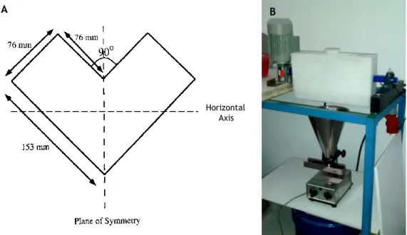
Figure 6.7 – Model of the inner structure of the machined PTFE V-blender made of two hollow cylindrical shells joined at an angle of 90º ... 39
Figure 6.8 – Schematic drawing of the set up put in place for powders blending OQ ... 46
xviii
xviii
Figure 6.10 – Schematic drawing of the result of TestSamples CNC code ... 49
Figure 7.1 – V-blender horizontality testing made using a level tool ... 58
Figure 7.2 - HA, MCD and HA/MCD apparent density curves after 0 minutes of blending on a 1 liter V-blender. ... 62
Figure 7.3 - HA, Al2O3 and HA/Al2O3 apparent density curves after 0 minutes of blending on a 1 liter V-blender. ... 62
Figure 7.4 - HA, MDC and HA/MCDapparent density curves after 3 minutes of blending on a 1 liter V-blender ... 63
Figure 7.5 - HA, MCD and HA/MCD apparent density curves after 5 minutes of blending on a 1 liter V-blender ... 64
Figure 7.6 - HA, Al2O3 and HA/Al2O3 apparent density curves after 3 minutes of blending on a 1 liter V-blender ... 64
Figure 7.7 - HA, Al2O3 and HA/Al2O3 apparent density curves after 5 minutes of blending on a 1 liter V-blender ... 64
Figure 7.8 – SEM imaging of hydroxyapatite (HA) and blast media MCD (sHA) and Al2O3. ... 65
Figure 7.9 - Scanning Electron Microscopy images of Ti-6Al-4V as received, HA blasted samples and CoBlast samples prepared using HA as dopant media and Al2O3 or MCD as blasting media ... 67
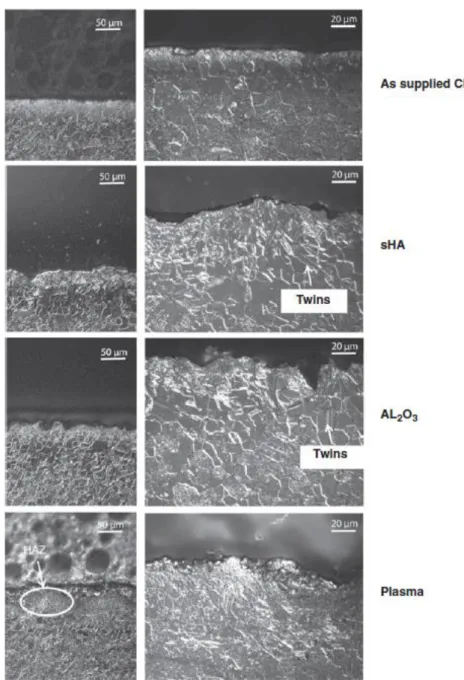
Figure 7.10 - Cross-sections of the Ti-6Al-4V coupons blasted with HA, HA/MCD and HA/Al2O3 for three different nozzle heights ... 68
Figure 7.11 – Coating thickness evaluation results ... 69
Figure 7.12 – Coating roughness evaluation before acid etching ... 70
Figure 7.13 - Coating roughness evaluation after acid etching ... 71
Figure 7.14 - Normalized XRD patterns ... 72
Figure 7.15 - Shewhart X-bar and R control chart of roughness profile of samples blasted over time with HA/MCD. ... 83
Figure 7.16 - Shewhart X-bar and R control chart of roughness profile of samples blasted over time with HA/Al2O3. ... 83
Figure 7.17 - Minitab® process capability report for roughness profile evaluation of HA/MCD blasted samples over time. ... 84
Figure 7.18 - Minitab® process capability report for roughness profile evaluation of HA/MCD blasted samples over time ... 84
xix
xix
List of tables
Table 2.1 - Existing calcium orthophosphates and their major properties ... 6
Table 6.1 – Programming quick reference for CoBlast using ... 37
Table 6.2 – Regulatory specifications for HA coatings. ... 42
Table 7.1 – Coatings thickness evaluation ... 69
Table 7.2 – Surface roughness before acid etching ... 70
Table 7.3 – Surface roughness after nitric acid at 65% etching ... 71
Table 7.4 – Ratio between the normalised intensity of 211 characteristic reflection of HA and 101 reflection of Ti corresponding to 31.5º and 40.2º (2θ), respectively... 73
Table 7.5 – D-spacing of the ten peaks used for HA coating crystallinity evaluation according to ISO 13779-3. ... 73
Table 7.6 – Integrated intensity of the peaks found in the XRD analysis of HA, Plasma, HA only, HA/MCD, HA/AL2O3 samples from the ones referenced in ISO 13779-3 for HA coating crystallinity determination. ... 74
Table 7.7 – Crystallinity according to ISO13779-3 ... 75
Table 7.8 – Crystallinity values obtained according to equation (7.1). ... 75
Table 7.9 – Highest peak of each phase to be identified if present in the samples analysed .. 76
Table 7.10 – Limits on heavy metals’ content as stated on ISO 13779-2 for HA coatings ... 78
Table 7.11 – Chemical elements detected using XRF analysis of samples coated using CoBlast with different nozzle heights ... 78
Table 7.12 – Adhesion tests performed according to ISO 13779-4 results ... 80
Table 7.13 – HA/MCD blasted surfaces over time roughness appraisal ... 81
Table 7.14 - HA/Al2O3 blasted surfaces over time roughness appraisal ... 81
Table 7.15 – Economic factors taken into consideration in the economical evaluation made... 87
xx
xxi
xxi
List of Abbreviations
List of abbreviations
ACP Amorphous Calcium Phosphates ALP Alkaline Phosphatase
Ang Angiopoietin APS Air plasma spray
ASTM American Society of Testing of Materials BCA Bicinchoninic Acid
bFGF Basic Fibroblast Growth Factor BG Bioactive Glass
CATiM Center for Technical Support to Metalworking Industry CDHA Calcium-Deficient Hydroxyapatite
CFR Code of Federal Regulations CO3A Carbonate Apatite
CNC Computer Numerical Control CVD Chemical Vapour Deposition DC Direct Current
ECDC European Centre for Disease Prevention and Control ECM Extracellular Matrix
EDX Energy Dispersive X-ray spectroscopy ESA European Space Agency
EU European Union FA Fluoro Apatite
FDA Food and Drug Administration
FEUP Faculdade de Engenharia da Universidade do Porto GHTF Global Harmonization Task Force
HA Hydroxyapatite
HAI Healthcare-Associated Infections HAZ Heat Affected Zone
HVOF High-Velocity Oxygen Fuel
IAPMEI Institute for Support to Small and Medium Enterprises and Investment ICP-OES Inductively Coupled Plasma Optical Emission Spectroscopy
iNOS Inducible Nitric Oxide Synthase IQ Installation Qualification
xxii
xxii
ISO International Organization for Standardization LCL Lower Control Limit
LSL Lower Specification Limit sHA Sintered Apatite
MgA Magnesium Apatite
MIB Integrated Master on Bioengineering MIT Massachusetts Institute of Technology
NASA National Aeronautics and Space Administration OQ Operational Qualification
PQ Performance Qualification PS Plasma-spray
PTFE Polytetrafluoroethylene PVD Physical Vapour Deposition PXRD Powder X-ray Diffraction RPM Revolutions Per Minute SBF Simulated Body Fluid
SEM Scanning Electron Microscopy SPC Statistical Process Control TCP Tricalcium Phosphate TRLs Technology Readiness Levels UCL Upper Control Limit
USA United States of America USL Upper Specification Limit VAC Volts in alternating current VPS Vacuum Plasma Spray WHO World Health Organization XPS X-ray Photoelectron Spectroscopy XRD X-ray Diffraction List of symbols θ Angle (-) Anode (+) Cathode ξ Mean ρ Density σ Standard Deviation V Volume ∆ Variation m Mass h Height
Chapter 1
Introduction
After the implantation of a medical device (e.g. orthopaedic device), a race for the surface takes place with bacterial colonization and tissue integration competing in order to conquer the surface of the implant (Gristina, 1987, Busscher et al., 2012). Bacterial biofilm may occur if the bacteria have the opportunity to adhere to the surface, divide and encapsulate themselves in a protective matrix that shields the bacteria from the effect of the systemically administered antibiotic. Subsequently, bacteria start to form colonies and the biofilm internal pressure may increase to a point where it bursts releasing the bacteria. This can cause infection of the surrounding tissue or expansion of the biofilm on a different location. When the infection persists local bone resorption takes place, leading to bone loss and implant loosening. On the other hand, eukaryotic cell adhesion (e.g. adhesion of osteoblasts) can lead to implant ingrowth followed by cell division and collagen matrix production. At last, subsequent calcification of the matrix allows bone apposition on the implant surface. Taking this into consideration, coatings that promote early tissue integration alone can be seen as a strategy to reduce infection.
1.1
Motivation
Each year, over six hundred million people are affected by healthcare-associated infections (HAI) worldwide with approximately 2% of the HAI being due to implantation of total hip and total knee prostheses, without taking trauma implants into account (WHO, 2012, ECDC, 2007). Trauma implants (e.g. plates, screws and stabilizing frames) have an even increased tendency for infection, mainly due to the fact that they are applied to repair complex injuries and open fractures. Infection together with the eventual loosening of an orthopaedic implant explains the limited lifespan of an orthopaedic device. HA-based coatings are still one of the most frequently used implant coatings in the field of orthopaedic surgery and trauma, resulting in improved implant ingrowth and a longer lifespan of the prosthesis (Capello et al., 2006).
Coatings may vary from releasing (e.g. RGD1 or antibiotic-containing coatings) to
non-releasing coatings (e.g. hydroxyapatite). Releasing coatings, are mostly applied to the surface
1 Extracellular matrix domain of three aminoacids, arginine (R), glycine (G) and asparagine (D), that
2
2
by dip or spin coating, due to their limited thermal stability, while non-releasing are normally applied using high temperatures which may damage crystallinity and create unwanted or amorphous phases. Sol-gel technologies or electrophoretic deposition can be used to coat porous alloys (e.g. titanium), but still the production of crack free coatings remains challenging (Boccaccini et al., 2010).
Therefore, it is urgent for innovative and effective coating technologies, that do not require high temperatures, to reach the market of medical coatings, since those may help to accomplish a combined situation of a coating with both antimicrobial and osteoconductive properties. CoBlast is a cleaning, roughening, and coating technology that works under room temperature and pressure, with minimal substrate alteration developed by a co-founder of a company named Enbio Limited, which can offer the solution this field is waiting for.
1.1.1. Ceramed
Ceramed is a Portuguese company created in 2005 after four years of incubation with the support of the Center for Technical Support to Metalworking Industry (CATiM). The company is specialized in medical devices coatings and its services comprise plasma-spray coating with titanium and hydroxyapatite, surgical instruments coating with Physical Vapour Deposition, and titanium anodizing. Ceramed was the first European company to be ISO 13485:2003 certified, and is also ISO 9001:2008 certified for medical devices coating services (2015a).
Partnerships of this company include several Portuguese and Spanish institutes and universities, Massachusetts Institute of Technology (MIT) Portugal, Enbio Limited Ireland, Medovent Germany, Institute for Support to Small and Medium Enterprises and Investment (IAPMEI) Portugal, Flemish Institute for Technological Research (VITO Belgium) and Veterinary Hospital of São Bento Portugal (2015b).
Recently, Ceramed premises were moved to Loures, and equipment from Enbio for the production of CoBlast coatings was acquired. The company intends to optimize and validate the process in order to make the coatings deposited with this innovative room temperature technology a new service available to its clients.
1.1.2. Enbio Limited
Enbio Limited is a partnership established by Ceramed in 2007. This company was founded in 2006 to exploit the CoBlast concept (2015c). Currently, Enbio focuses the production, research and development on coatings for aviation and aerospace industries made using CoBlast. The company is achieving great successes in this field, having recently developed a partnership with the European Space Agency (ESA) to develop thermal control coatings for the Solar Orbiter mission in 2017 (2015f).
1.2
Objective
This work intends to provide a solid review on the existing medical implant coating techniques and the basic principles observed and reported in the development of an innovative coating technique called CoBlast.
3
3
Furthermore, the aim of this dissertation is to elaborate a Master Validation Plan for CoBlast technology and perform the validation of this innovative coating process and its further implementation as a new service to be provided by Ceramed within the scope of medical devices coating.
1.3
Contributions
A review on calcium orthophosphates used in medical device coatings, coating processes frequently adopted in medical device industry and CoBlast invention and principles.
A thorough explanation on how and why a Process Validation of a manufacturing process for medical devices should be carried out, and a compilation of the regulatory specifications needed to be taken into account to successfully validate a process to produce HA coatings.
A Validation Plan for CoBlast technology, the protocols and the results of all the tests performed at Ceramed. An economical appraisal of the process and future recommendations.
1.4
Document Structure
This dissertation is organized in seven major chapters: Introduction, Bioactive coating materials, Overview of medical device coating processes, CoBlastTM, Process Validation,
CoBlast Validation Plan and CoBlast Process Validation.
The present chapter, Introduction, brings out the motivations, objectives and contributions of this dissertation.
Chapter 2 clarifies the importance of bioactive coatings in the medical field with a wide-ranging analysis of the use of calcium orthophosphates in orthopaedic prosthesis.
Chapter 3 provides an overview on the most frequently adopted medical device coating processes in medical industry in order to understand their properties, their weaknesses and strengths, and the global landscape where CoBlast will be inserted.
Chapter 4 presents the state-of-the-art of CoBlast technology since its invention until nowadays. It summarizes CoBlast processing principles and provides a small review of publications.
Chapter 5 reveals Process Validation within the Quality Management System requirements and its applicability to manufacturing processes for medical devices. A synopsis of statistical concepts, important considerations, and steps of process validation is made.
Chapter 6 focuses on the planning of CoBlast validation conducted at Ceramed and discloses the Validation Protocol implemented in the first validation of CoBlast. An overview on the equipment installed, raw materials used, parameters studied, requirements of the process and a clarification to the strategy adopted is made here.
Chapter 7 reveals the results obtained during the implementation of CoBlast validation protocol and infers about the state of validation of this process. This chapter is a validation report itself. Furthermore this chapter includes an economic analysis of the process in order to infer about the costs involved in a situation of production with the equipment and parameters in place.
4
Chapter 2
Bioactive coating materials
Most metals used in medical implants lack biologically active surface that promote osteointegration or wards off infection. Research over the years focused on finding the best materials to develop a range of coatings with the ability to improve implant binding to the host bone tissue.
Bioceramics, extracellular matrix proteins, biological peptides or growth factors have been used to enhance bioactivity and biocompatibility to the metallic surface of conventional orthopaedic prosthesis (Zhang et al., 2014). Coatings must be biocompatible in order not to trigger significant immune or foreign-body response, osteoconductive to promote osteoblasts adhesion, proliferation and growth on the surface of the implant to form a secure bone-implant bonding and osteoinductive to recruit various stem cells from surrounding tissue and circulation and induce differentiation into osteogenic cells (Albrektsson and Johansson, 2001). Furthermore the coating must have sufficient mechanical stability to withstand stresses associated with locomotion without detaching from the implant surface. Ultimately, addition of silver, nitric oxide, antibiotics, antiseptics and antimicrobial peptides, can improve anti-microbial properties minimizing the risk of prosthetic infection (Zhang et al., 2014).
2.1.
Calcium orthophosphates
Calcium orthophosphates became known in history due to their great chemical similarity to the inorganic part of bones and teeth of mammals (Dorozhkin, 2013). All calcium orthophosphates (listed in Table 2.1) consist of three major chemical elements: calcium (oxidation state +2), phosphorus (oxidation state +5), and oxygen (oxidation state −2). The chemical composition may include hydroxyl ions as an acidic orthophosphate anion such as HPO42− or H2PO4−, and/or incorporated water as in dicalcium phosphate dihydrate (CaHPO4 ·
2H2O) (Dorozhkin, 2007). Most calcium orthophosphates are moderately soluble in water, but
all dissolve in acids. Calcium to phosphate molar ratio (Ca/P) and solubility are important parameters to distinguish between the phases (i.e. phase purity and crystallinity have major influence on solubility) (Wang and Nancollas, 2008).
Hydroxyapatite (HA), one of the least soluble calcium orthophosphate, is a bioactive material that in a dense state dissolves slightly, but promotes the formation of a biological
6
6
apatite layer before interfacing directly with the tissue at the atomic level resulting in the formation of a direct chemical bond with bone. Less dense composites of tricalcium phosphate (TCP) and HA (i.e. β-TCP+HA and α-TCP+HA) or calcium-deficient hydroxyapatite (CDHA) and/or amorphous calcium phosphates (ACP) appear to be the good bioresorbable materials that dissolve and allow a newly formed tissue to grow into any surface irregularities but may not necessarily interface directly with the material (Dorozhkin, 2007).
Due to their poor mechanical properties (i.e. brittleness), bulk calcium orthophosphates bioceramics have limited load-bearing applications. The application of calcium orthophosphates coatings on metals, which support high loads but do not form mechanically stable links between the implant and bone tissues, allows the implant to participate in bone remodelling responses similar to natural bones. Phase purity and crystallinity of such coatings will have major influence on coating solubility, influencing coatings stability and bone response (Dorozhkin, 2012, 2009, 2011, 2013, Wang and Nancollas, 2008).
Plasma-spray is the most used and accepted method for HA coating application. Due to the high temperatures achieved during this deposition process, coating crystallinity decreases, and phase transformations may occur. Plasma-sprayed HA-coated implants are essentially composed of a mixture of crystalline, amorphous, and non-apatite phases such as Ca3(PO4)2 (TCP), Ca4(PO4)2O (TTCP) or even CaO. The presence of TCP and TTCP phases may
enhance the resorption process of HA coating leading to implant instability (Klein et al., 1994, Radin and Ducheyne, 1992). Therefore, it is important to explore other coating Table 2.1 - Existing calcium orthophosphates and their major properties. From Dorozhkin (2009) and Dorozhkin (2011) cited in Dorozhkin (2012).
7
7
techniques that do not require high temperatures for the application of HA bioactive coatings that promote osteogenesis and prevent infections.
Requirements and regulations for HA coatings are described in the Food and Drug Administration (FDA) guidelines as well as in the ISO standards and European Medical Regulations (Veselov et al., 2012).
8
Chapter 3
Overview of medical device coating processes
Surface modification of medical devices has been adopted over the years to retain key bulk properties of the device material while modifying the surface to improve biocompatibility. These surface engineering strategies tailor chemical and structural properties in a thin surface layer of the substrate in order to meet with design and functional requirements. This chapter gives an insight on the most commonly applied surface modification processes used in the medical field.
3.1
Abrasive blasting
Techniques such as grit blasting, shot blasting, sand blasting, shot peening and micro abrasion generally involve the mixing of an abrasive material with a fluid and delivery at high velocity to impinge the surface to be treated, and are here stated as abrasive blasting techniques. The delivery of the abrasive material can be classified as wet or dry depending on the fluid medium used to deliver the abrasive to the surface, gaseous or liquid.
Abrasive blasting techniques have many applications like metal cutting, cold working metallic surfaces and pre-treatment of surfaces to create surface roughness to improve further coating materials adhesion. In the biomedical sector, titanium implants are regularly grit blasted with alumina or silica to create a level of surface roughness that maximizes the adhesion of plasma sprayed HA coatings on the surface of the implants (Yang et al., 2009).
3.2
Thermal spraying techniques
Thermal spraying comprises a group of processes in which metallic and non-metallic materials are deposited in a molten or semi-molten state on a prepared substrate (Pawlowski, 2008). It uses a concentrated heat source to melt feedstock materials and process jets to propel the molten particles toward a prepared surface. The heat source can be generated chemically through combustion of fuels with oxygen or air, or electrical heating of industrial gases. Devices used to achieve this work are called guns or torches (Davis and Committee, 2004).
10
10 3.2.1. Plasma spray
In plasma-spray processing, powder materials are injected into a high temperature plasma2 (i.e. radio frequency discharges) or plasma jets (i.e. direct current arc) being rapidly
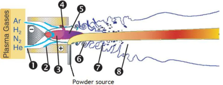
heated and accelerated before they flatten and solidify onto the substrate. Conventional direct current (DC) arc spray torch is represented in Figure 3.1. Temperatures over 8000K at atmospheric pressure are normally reached allowing the melting of any material. In order to avoid low deposition efficiency, the melting temperature must be at least 300K lower than the vaporisation or decomposition temperature (Fauchais, 2004).
Characteristic coatings of HA deposited using plasma spray are 20-300 µm thick and 3-6 µm rough (Sun et al., 2001). It was verified an increased cell proliferation on plasma-sprayed HA-coatings when compared with simply HA-grit-blasted surfaces (Borsari et al., 2005).
Oxide formations are frequent in air plasma spray (APS) processing. An option to avoid those is plasma-spray process conducted under controlled-environment spraying like low pressure or vacuum plasma spray (VPS). It is able to produce clean coatings with virtually no oxide inclusions (Davis and Committee, 2004).
3.2.2. Flame spray
Conventional flame spray requires combustion of a jet of fuel and oxygen in front of the torch, external to nozzle. Fuel and oxygen rates and ratio can be adjusted to induce the desired thermal output. Oxyacetylene torches are the most common, using acetylene as fuel in combustion with oxygen to generate high combustion temperatures. During processing the jet gas speed is below 100 m/s, and particles reach 80 m/s before impact. Open-flame (i.e. externally combusted) jet temperatures are generally above 2900K, and are controlled by mixing patterns of the combustion gases with the surrounding air as well as by the combustion
2 Plasma is the term used to describe gas which has been raised to such a high temperature that it
ionizes and becomes electrically conductive (Birka et al., 2012).
Figure 3.1 – Schematic of a conventional DC arc spray torch with a nozzle composed by a stick type thoriated tungsten cathode (+) and a anode (-); 1 – Plasma forming gas injection, 2 – Cold boundary layer ate the anode wall, 3 – Arc column, 4 – Connecting arc column, 5 – Plasma jet exiting the nozzle, 6 – Large scale eddies, 7 – Surrounding atmosphere bubbles entrained by engulfment process, 8 – Plasma plume. Adapted from Fauchais (2004).
11
11
temperatures of the fuel/oxygen mixture. Powder is fed into these spray torches either by carrier gases or by gravity (Davis and Committee, 2004).
3.2.3. High velocity oxygen fuel (HVOF)
High velocity oxygen fuel (HVOF) requires extended internal-confined combustion and operates on a continuous, steady-state basis. High volume combustible gases are fed into a combustion chamber, like a long confining nozzle or barrel, through which the combustion gases exit the device with velocities ranging from 1525 to 1825 m/s, at the nozzle exit. High velocity combustion spray devices can be divided into two distinct classes according to their combustion chamber pressure: high velocity (i.e. pressure exceeding 241 kPa and heat inputs of 527 MJ) and hypervelocity (i.e. pressure ranging from 620 to 827 kPa and heat inputs of approximately 1GJ). These last use normally kerosene as fuel and air or oxygen to support combustion. The HVOF guns are air or water cooled where fuel/oxygen mixtures under pressure accelerate the gas stream down a confined cooled tube or nozzle. Powder materials are fed into the nozzle borne by a carrier gas, and become entrained into the confined high pressure flame/jet (Davis and Committee, 2004).
3.2.4. Electrical arch spray
Electrical arch spray, also called twin wire arc, arc spray or wire arc spray, uses a DC electric arc between two consumable electrode wires performing direct melting of particles. Molten particles are sprayed through the surface by a high-velocity air jet located behind the intersection of the wires, as the wires are fed into the arc and melted. The airflow ranges from 0.8 to 1.8 m3/min at up to 690 kPa, as the power supply design of the arc limits most
systems to operating above 50A DC. Since the wires are melted directly by the arc in this technique, higher thermal efficiency is registered when compared with other thermal spray processes. However, the droplets are already molten when picked up and entrained in the jet, and, unlike other processes, the particles begin to cool immediately after leaving the arc zone. In order to minimize this effect combined with the effect of oxidation, short standoff distances and high atomizing air flows can be used (Davis and Committee, 2004).
3.3
Electrodeposition
Electrodeposition is a useful process for applying thin films to electrically conductive surfaces. In its simplest form, also known as electroplating, there is an electrodeposition bath containing metal ions, an electrode or substrate on which the deposition is desired, and a counter electrode. When a current flows through the electrolyte, the cations and anions move, according to their charges, toward the cathode and the anode, and may deposit on the electrodes after undergoing a charge transfer reaction. This process is directly related with Faraday’s laws of electrolysis. Faraday’s second law relates the mass (∆m) deposited over a unit area to the current density j flowing for a time t:
12
12
An important implication of Faraday’s second law is that the ratio of the mass of the electrodeposit to its gram-equivalent weight is a constant equal to 96,500 coulombs. The amount of material electroplated depends directly upon the current on the substrate, and thus, a uniform current distribution is compulsory to generate a uniform film. Most materials that can be deposited through electrodeposition can roughly be delivered using other physical or chemical methods (e.g. thermal-spray, chemical vapour deposition, physical vapour deposition), nevertheless, electrodeposition can be more cost-effective in some applications (Pandey et al., 1996).
3.4
Sputtering
Sputtering is known as a deposition process capable of grow thin films of material on a substrate that uses irradiation of energetic species. The phenomenon occurs when a solid surface is bombarded with energetic ions and surface atoms of the solid are scattered backward due to collisions between the surface atoms and the energetic particles. Typical sputtering systems include DC diode, radiofrequency diode, magnetron diode and ion bean sputtering. The simplest model is the DC diode sputtering system composed by a pair of planar electrodes, a cathode and an anode, inside a sputtering chamber. The front surface of the cathode is conveniently covered with target materials to be deposited, as the substrates are placed on the anode. The sputtering chamber is filled with gas (e.g. Argon) at 1 to 5 Pa. Under the application of DC voltage between the electrodes, a glow discharged is maintained and Ar+ ions formed in it are accelerated at the cathode fall and sputter the cathode target
resulting in the deposition of thin films of the cathode target on the substrates (Wasa, 2012). Conventional sputtering techniques have shown some advantages over the commercially available plasma spraying method, the most utilized technique to deposit HA. However, sputtered films are usually amorphous which can cause some serious adhesion problems when post-deposition heat treatment is needed (Hong et al., 2007).
3.5
Chemical vapour deposition (CVD)
Every chemical vapour deposition (CVD) process involves reactions that create a solid from gases in a synthesis process in which the chemical constituents react in the vapour phase near or on a heated surface. The material to be deposited is vaporized and is injected into the CVD chamber to make their way to the substrate. When the gaseous compounds react the solid deposit is formed as well as by-products gases which are removed by gas flow through the reaction chamber. In CVD the absolute temperature varies from 300K to 1200K, and pressure varies from few 0.1 Pa (i.e. low pressure chemical vapour deposition) to 100 kPa (i.e. atmospheric pressure chemical vapour deposition). The use of precursor chemicals almost always introduces impurities in the solid films (Dobkin and Zuraw, 2003).
13
13
3.6
Physical vapour deposition (PVD)
Physical vapour deposition (PVD) is a process in which a material to be deposited is vaporized from a solid or liquid source and transported in the form of a vapour through a vacuum or low pressure gaseous or plasma environment to the substrate, where it condenses (Mattox, 2010). The vacuum deposition comprises evaporating the source material in a vacuum chamber below 1x10⁻⁴ Pa. Kinect energies of evaporating source material atoms are
1000-3000K and can be attained by resistive heating or electron beam deposition. PVD rate of condensation of vapour depends on the evaporation rate of the source material, source geometry and its position relative to the substrate, and condensation coefficient. The method allows the treatment of substrates with complex geometries and very small to very large size (Wasa, 2012).
3.7
Pulsed laser deposition (PLD)
A pulsed laser deposition (PLD) system is composed by three essential parts: substrate, solid target and laser source (Figure 3.2). The principles of action are similar to the ones explored in other processes herein explored, where the material of the target experiences evaporation and subsequent condensation on the substrate. The evaporation occurs as consequence of the incidence of laser pulses. There are many classes of high-power ultraviolet pulsed lasers, being Nd:YAG and KrF excimer (1 J/cm2) the most successfully used
in HA deposition (Kurella and Dahotre, 2005).
Figure 3.2 - Typical pulsed laser deposition (PLD) system. Laser pulses, irradiated though a quartz window, evaporate the target materials which condense on the substrate. From Zeng and Lacefield (2000).
14
14
3.8
Sol-gel immersion technique
Sol-gel processing requires colloidal suspensions (i.e. sols) conversion to viscous gels and drying. A wide range of inorganic and organic/inorganic composite materials can be prepared using this approach. Sol-gel thin layers can be applied to substrates using both spin coating and dip coating. In spin coating process the film is applied and dried in a few seconds, whereas in dip coating the film is applied at a rate of few centimeters per minute. Both techniques result in an inverse relation between the thickness of the film and its density: thin films are denser than thick films. These techniques allow the preparation of composite coatings which cannot be obtained by other methods, such as organic-inorganic hybrid materials (Wright and Sommerdijk, 2000).
3.9
Sintering
Sintering processing comprises the application of thermal energy to a powder compact, densifying it and increasing the average grain size (Kang, 2004). It aims to produce sintered parts with reproducible and designed microstructure through control of sintering variables (e.g. powder shape, size, composition, sintering temperature, time and pressure). Sintering is a process that leads to a reduction of the total interfacial energy of the powder compact. Ceramic coating sintering can result in considerable coating thermal conductivity and elastic-modulus increase, but can also lead to shrinkage-cracking, eventually causing spallation of the coating (Xu and Guo, 2011).
Chapter 4
CoBlast
TM
CoBlastTM is a one-step metal transformation technology developed by John O’Donoghue,
co-founder and current co-director of Enbio Limited. This technology is commercially applied to remove a metal’s oxide layer and replace it with a desired functional coating. (2015d) It uses conventional grit-blasting or micro-blasting equipment, and is performed at room temperature and pressure. These properties allow it to be applied to sensitive substrates without damage, preserving properties that are easily destroyed by heat treatment processes. Simultaneous roughening, chemical activation and coating adhesion achieved with this technique are great for substrates that normally surfer poor coating adhesion. Currently, CoBlast is a surface treatment with its basic technology research complete in respect to biocompatibility, lubrication and hydrophobicity in the medical field (Figure 4.1) (2015e).
Technology readiness levels (TRLs) are used as the metric to assess the maturity of a technology. It consists in a scale developed firstly by National Aeronautics and Space Administration (NASA) in the 70s, that was lately approved by the Department of Defense Figure 4.1 – CoBlast technology readiness level concerning properties like thermo-optical control, biocompatibility, corrosion resistance, lubrication, hydrophobicity in the fields of space, aerospace, oil and gas, oceanic, industrial, and medical. From 2015c).
16
16
(DOD) of the United States of America (USA) and adopted world-wide (Mankins, 2009). TRL scale ranges from one to nine with definitions as followed (DOD and (DUSD(S&T)), 2003) :
TRL 1: Basic principles observed and reported;
TRL 2: Technology concept and/or application formulated;
TRL 3: Analytical and experimental critical function and/or characteristic proof-of-concept;
TRL 4: Component and/or breadboard validation in a laboratory environment; TRL 5: Component and/or breadboard validation in a relevant environment;
TRL 6: System/subsystem model or prototype demonstration in a relevant environment; TRL 7: System prototype demonstration in an operational environment;
TRL 8: Actual system completed and qualified through test and demonstration; TRL 9: Actual system proven through successful mission operations.
4.1
Invention
CoBlast is the trade name for a method of doping surfaces patented by O'donoghue and Haverty (2008), that comprises the removal of the oxide layer from a metal’s surface and provision of dopant particles in fluid jet that impregnates the surface with the dopant.
Invention background lies in surface treatment techniques of bombardment of metal surfaces with abrasive materials, e.g. abrasive blasting techniques. Knowing that during the blasting some of the abrasive metal becomes impregnated in the surface of the metal, attempts of using abrasive blasting techniques as a means of putting a hydroxyapatite layer directly onto titanium surfaces were made (Ishikawa et al., 1997). Still, since the deposited layer could be removed under ultra-sonication with water after few minutes, it seems like no proper bond with the surface of the metal is achieved.
In this method, the metal oxide layer is removed by abrasively blasting the metal oxide surface with an abrasive material – e.g. silica, alumina, zirconia, barium titanate, calcium titanate, sodium titanate, titanium oxide, glass, biocompatible glass, diamond, silicon carbide, calcium phosphate, calcium carbonate, metallic powders, metallic wires, carbon fiber composites, polymers, polymeric composites, titanium, stainless steel, hardened steel, chromium alloys – by the same means used on the exploited abrasive blasting techniques described in section 3.1. This process focuses on the intentional addition of a material of choice to the surface – the dopant – that can be a polymer, metal, ceramic and combinations thereof. Respecting biomedical applications the dopant can be hydroxyapatite, modified calcium phosphates, therapeutic agents, silica, zirconia, biocompatible glass, carbon, chitosan/chitin, and others. These last can induce desirable chemical, physical and biological properties on the surface of biomedical implants. The addition of the dopant happens prior to reoxidation of the newly formed oxide layer. To prevent its early formation the removal of the oxide layer can be performed under an inert atmosphere. This procedure takes, thus, advantage of the inherent reactivity of metals to modify their surface. By having an abrasive impacting with sufficient energy (i.e. a material with sufficient particle size, density and hardness) to break the oxide layer and feeding the surface simultaneously with a dopant material, this last may be taken up while the oxide layer reforms around it. Thereof, the dopant material can become strongly bound within the oxide layer of the surface.
Different approaches can be adopted to achieve this. In one embodiment there is an almost synchronously delivery of a first set of particles containing a dopant and a second set
17
17
of particles with an abrasive from one fluid jet to a surface of an article to impregnate the surface of the article with the dopant (Figure 4.2).The energy dissipated at the impact site of the abrasive may be sufficient for the dopant to become ceramicised or otherwise bonded to the surface.
Dopants and abrasives can be either contained in the same reservoir and delivered to the surface from the same jet (nozzle) or separated in different reservoirs and delivered by multiple jets. Three different nozzle configurations can be implemented to deliver dopant particles and abrasive particles to the surface (Figure 4.3). A single nozzle can be used as previously stated (Figure 4.3, A) or a combination of multiple nozzles (Figure 4.3, B and C) where two or more streams of particles are used where at least one stream abrasively blasts the oxide surface to expose the new metal surface and another stream bombards the new metal surface with dopant.
Concerning multiple jets, the particles of each jet can have the same (Figure 4.3, B) or different incident angles hitting the same spot on the surface simultaneously (Figure 4.3, C). To sum up, the final variables that must be considered in order to apply this technology are the abrasive particle, the abrasive particles size, the dopant, the dopant particles size, the stream carrier fluid (i.e. gaseous, liquid, basic etching liquid, acidic etching liquid), the number of nozzles used, incident angle(s) (ranging from 10 to 90º) power feeder pressure (ranging from 50 to 10000 kPa), deposition direction, speed of the movement of the nozzles over the surface, distance of the nozzles to the surface and raster offset. This topic is further explored in the following section 4.2.
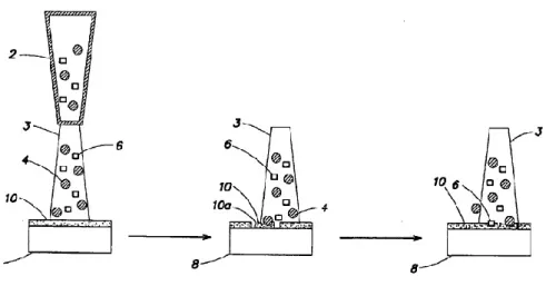
Figure 4.2 - CoBlast application approach using fluid jet (nozzle) (2) to bombard the surface (10) of the substrate (8) with abrasive (4) and dopant particles (6) almost simultaneous in the same stream (3). During the impact of the abrasive particles a new surface (10a) of the substrate is exposed. From O'donoghue and Haverty (2008).
18
18
The working ability of these systems is related with the use of converging-diverging nozzles, commonly known as De Laval nozzles. Converging-diverging characteristic design of the De Laval Nozzle allows the generation of supersonic gas exit flow velocity after a subsonic entry velocity. It was named after Karl Gustaf Patrik de Laval by the end of the 19th century
and is often employed in propelling equipment like rockets and high-pressure jet engines.
4.2
Deposition conditions and parameters
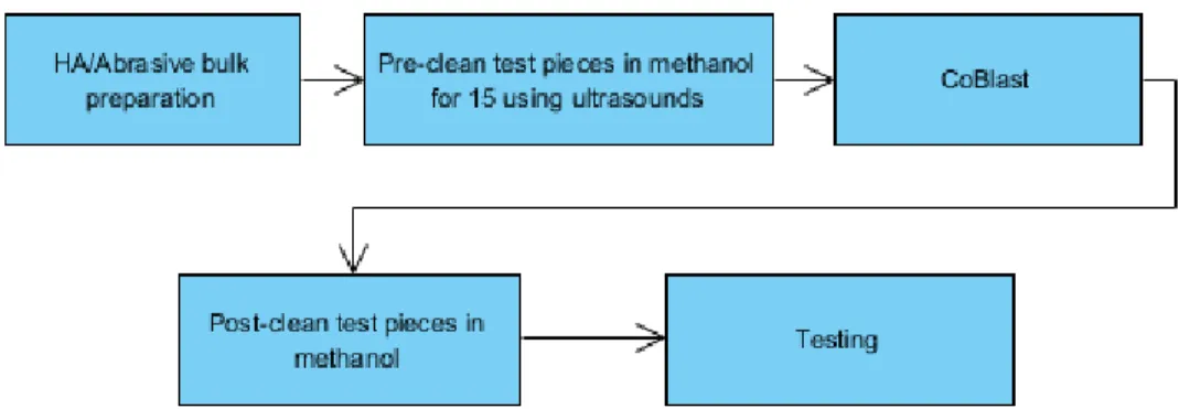
CoBlast pre-deposition processing can include steps like mechanical polishing of substrates (e.g. using 1200 grit size silicon carbide paper) to provide uniform surface roughness (Barry and Dowling, 2012, Tan et al., 2012, Barry et al., 2013). Frequently, metal substrates are washed with 1M HCl (O'Hare et al., 2010, Keady and Murphy, 2013) and ultrasonically cleaned using isopropanol (O'Hare et al., 2010, Fleming et al., 2011, Keady and Murphy, 2013) to remove any contaminants. When metal polish is preformed, methanol and acetone ultrasonic wash is generally applied to remove loosely adherent particles (Barry and Dowling, 2012, Tan et al., 2012, Barry et al., 2013).
CoBlast processing is regularly applied using twin nozzles to deliver one stream of dopant and one stream of abrasive to a common area on the substrate surface (i.e. “blast-zone”) (Keady and Murphy, 2013, Byrne et al., 2013, Barry et al., 2013), or using a single nozzle where dopant and abrasive are part of a mix media sprayed at the substrate in the same stream (O'donoghue and Haverty, 2008, Dunne et al., 2013). The angle of deposition can be adjusted, and it is common to be adopted an angle ranging from 75º to 82º when two nozzles are used with different nozzle angle for the abrasive and the dopant (Tan et al., 2011, Fleming et al., 2011) or the same angle for the abrasive and the dopant (Tan et al., 2012), or Figure 4.3 – Schematic diagrams of three different nozzle configuration to deliver the dopants and abrasives of CoBlast to a surface at a distance D: single nozzle (A), multiple nozzles with dopants and abrasives delivered from separate reservoirs where one nozzle is within another nozzle (B), and multiple separate nozzles with dopants and abrasives delivered from separate reservoirs (C). Elements: 20 – single nozzle; 23 – single stream; 24 – abrasive particles; 26 – dopant particles; 28 – substrate; 30 – one nozzle; 33 – stream of abrasive particles; 40 – another nozzle; 43 – stream of dopant particles. From O'donoghue and Haverty (2008).
19
19
90º when a single nozzle is used (Dunne et al., 2013, Dunne, Twomey, and Stanton, 2015, Dunne, Twomey, Kelly, et al., 2015).
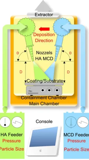
Figure 4.4 presents in red the deposition parameters that according Tan et al. (2012) are essential to acquire HA coatings and in black the core components of a CoBlast processing system with two nozzles. Nozzles height (i.e. distance to the surface), nozzles speed over the surface, and feed pressure are often settled to a range between 8 and 23 mm, 12 and 15 mm/s (Fleming et al., 2011, Tan et al., 2012, Keady and Murphy, 2013), and approximately 414 to 620 kPa (Fleming et al., 2011, Tan et al., 2012) respectively.
When a single nozzle is used, it is held at 90º to the surface (O'donoghue and Haverty, 2008). Its height is settled at 50 mm and pressure of the feeder ranges approximately from 500 to 550 kPa (O'donoghue and Haverty, 2008, Dunne et al., 2013).
The perfect combination of such parameters will be always dependent on the type of substrate, powder particles, and fluid carrier used. Nevertheless, the implementation of such standards is based on the experience of research teams that work directly and repeatedly Figure 4.4 – Schematic of CoBlast deposition system with two nozzles. Θ stands for the deposition angle and D for the distance to the substrate. MCD is a commercial granular apatitic abrasive made of sintered apatite (sHA). Black texts represent the core components of the system while red texts are the essential parameters to acquire the coatings. Adapted from Tan et al. (2012).
20
20
with CoBlast and, thus, has its intrinsic value. Unanimously, compressed air was used as fluid carrier by all of the groups mentioned herein.
Substrates are bombarded to ensure that the area of interest is covered. When more complex shapes pieces are processed by CoBlast, several strategies can be adopted. Keady and Murphy (2013) performed a three passes process applying 120º rotations to completely coat a wire. The same team coated stents by placing them in a mandril, rotating the mandril and coating the stent with a helical pattern.
Post-deposition processing may include air-cleaning of the samples using compressed air (O'Neill et al., 2009, O'Sullivan et al., 2010) sonication in isopropanol (Tan et al., 2011), storage in a desiccator and autoclave processing at 121ºC for 20 minutes prior to packaging and use. Samples may also be simply ultrasonically washed in de-ionized water (O’Sullivan et al., 2011, Barry and Dowling, 2012), to remove any loose powder from the surface, followed by autoclave prior to use.
4.3
Reviewed Publications
O'Neill et al. (2009) reported on the capability of CoBlastprocess to deposit substituted apatites. Water contact angle of Ti-6Al-4V surface treated sheets with HA, Fluoro apatite (FA), Magnesium apatite (MgA) and Carbonate apatite (CO3A) revealed significant surface
modification for each material. XPS analysis showed that all surfaces exhibit minimal levels of titanium and high amounts of Ca, P, O and C after treatment consistent with complete treatment of the accessible surface. EDX revealed otherwise, finding significant levels of titanium in samples pointing to a limited depth of treatment. Adventitious carbon was also found in the XPS analysis. Coating thickness was estimated between 7 and 10 µm and SEM images unveiled roughening by the abrasive blasting and regions of titanium which appear to be folded in the outer HA layer in the metal-HA interface. Such apatite adhesion was attributed to the combination of kinetic energy resulting tribochemical bonding with mechanical interlocking due to substrate surface disruption. Standard tape adhesion test (ASTM D3359-02) lead to no evidence of coating delamination on each coated sample. The present study exposed also that substituted apatites had higher ion release likely attributed to the lower level of crystallinity determined by XRD. Finally, MTT assay showed comparable levels of MG-63 osteosarcoma-derived cell proliferation after 24h and significant enhanced cell proliferation on the carbonate samples after 72h. The authors conclude by saying that the combination of ion elution and XRD analysis suggests that the crystallinity of the dopant is conserved in the coating process as expected in a non-thermal processing method like CoBlast.
A year later, O'Hare et al. (2010) characterized the difference between surfaces produced by simple HA surface blasting and surfaces treated with CoBlast using alumina (Al) as abrasive and HA as dopant. In vitro response of osteoblast-like cells and bone growth in an in vivo animal model were observed. XPS surface analysis revealed the chemistry of the outermost surface region with significant levels of Ca, P and O on both samples (i.e. HA-microblast and CoBlast), and no significant level of titanium, suggesting effective deposition of HA into the surface and good surface coverage with both techniques. Differences between the two surfaces were found using EDX and Secondary Ion Mass Spectroscopy (SIMS): a smooth