Revista Sul-Americana de Engenharia Estrutural
ISSN 2316-2457Humberto Araujo Machadoa,b, e-mail:[email protected], [email protected]
F. M. Monticelib, e-mail: [email protected]
L. H. Coutinho Jr.b , e-mail: [email protected]
P. N. Linharesb , e-mail: [email protected]
Newton G. C. Leiteb , e-mail: [email protected] , [email protected]
a- Departamento de Ciência e Tecnologia Aeroespacial – DCTA, Instituto de Aeronáutica e Espaço – IAE, Av. Brigadeiro Faria Lima, 1.941, Parque Martim Cererê, São José dos Campos – SP, CEP 12.227-000
b- Universidade do Estado do Rio de Janeiro – UERJ, Faculdade de Tecnologia - FAT Departamento de Mecânica e Energia – DME, Centro de Fontes Renováveis de Energia – CFRE, Rodovia Presidente Dutra, km 298, Pólo Industrial, Resende – RJ, CEP 27.537-000
ECONOMIC VIABILITY OF THERMO-STRUCTURAL INTEGRATED SYSTEM IN THE SARA SUB-ORBITAL PLATFORM
Humberto Araujo Machado a,b; F.M. Monticellib;, P.N. Linharesb;Newton G.C.Leite
Abstract: Space and suborbital vehicles reach high speeds while flying in the atmosphere, which results in aerodynamic heating and structural loads due the dynamic pressure on the surface. High resistance materials are employed to support such requirements, increasing the spacecraft weight and launching costs. The use of an integrated thermal structural protection (TISSC) was proposed, in order to improve the overall performance, resulting in a significant reduction in weight and cost and increasing the life cycle of the vehicle. This work is aimed in analyzing the economic viability of these structures, applied to the SARA suborbital platform, which is being developed by IAE (Institute of Aeronautics and Space) for experiments in micro-gravity environment. Possible combinations of materials to be employed, including their cost and manufacturability, were analyzed, concluding that the use of this system represents an advantage when compared to the conventional thermal protection system.
Keywords: Transport engineering; modern transport; friendly environmental transport; sustainable transport.
INTRODUCTION
Space and suborbital vehicles reach high velocities within the atmosphere, which results in aerodynamic heating and high wall heat fluxes. The high temperatures may negatively affect the mechanical behavior of the structures and the operation of on board equipment, besides the fact that payload preservation is always mandatory. These problems are solved by using an efficient Thermal Protection System (TPS). As a consequence, TPS design is a critical aspect of a rocket design, since under sizing may result loss of the payload, and the oversizing implies in increasing mass and cost.
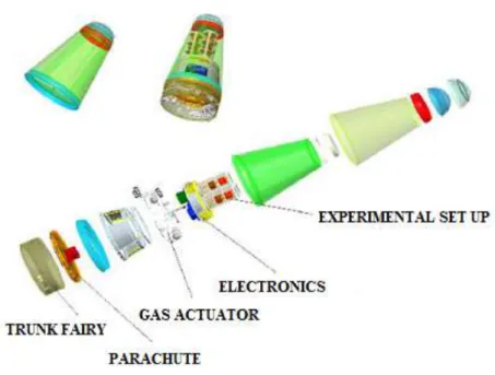
Suborbital platforms are a low-cost alternative for micro-gravity research. SARA sub-orbital platform, Fig. 1, is being developed by IAE/CTA for such application. It has a total mass of 250 kg for a payload of about 25 kg and is designed to provide 6 minutes of micro-gravity environment. SARA reaches the speed of 9300 km/h in atmospheric flight (Moraes, 1998).
Figure 1. SARA sub orbital and its internal systems.
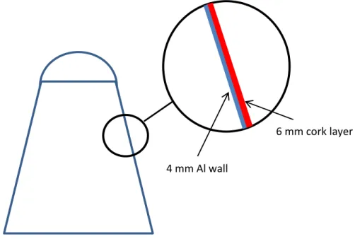
The current design uses a conventional cork layer as TPS to protect its lateral surface, with the trade-off of large mass. As an option, Thermally Integrated Structural Sandwich Core (TISSC) would insulate the vehicle from aerodynamic heating as well
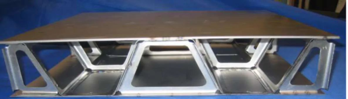
as carry primary vehicle loads (Poteet and Hsu, 2004). It consists of a structural sandwich panel in a three-layer plate with two face sheets and a core. Two thin, stiff and strong faces are separated by a thick, light and weaker core, Fig. 2. The advantages of using such a structure are that it is lightweight, multifunctional, offering insulation as well as load bearing capabilities, low maintenance, and low life-cycle cost. Commonly used materials for facings and core are ceramic matrix composite laminates and metals.
4 mm Al wall
6 mm cork layer
Figure 3. Schematics of current TPS design - Sandwich Core (TISSC) – NASA concept.
A Thermally Integrated Structural Sandwich Core (TISSC) was proposed to replace SARA´s current thermal protection system, and the results were presented in a previous work (Machado et al., 2013). In that work the TISSC was demonstrated to provide higher strength than the current configuration of the TPS/structure design.
TPS modifying straightly results in a mass variation of SARA platform, which influences dimensioning and material choices and consequently, the final trajectory, manufacturing and launching costs. All those parameters must be selected in order to find the equilibrium point (Machado & Leite, 2010). In this work, the economic feasibility of such replacement is studied, through the comparison between the costs of the current thermal protection and the proposed TISSC configuration. Some material
combinations are tested, considering their costs and manufacturing processes in order to determine the best options and its viability in replacing the current TPS design.
Figure 2. Thermally Integrated Structural.
Behind the mass, the cost is also influenced by the time available for the experiment performing within the payload. The corresponding costs for several micro-gravity facilities are showed in Fig. 4 (Corrêa & Moraes 1999). In this work, the benchmark adopted was the sounding rocket value, with a microgravity cost of US$ 10,000 for kg.h, resulting in 7a total amount of US$ 250,000 for a whole SARA mission (25 kg payload during 6 minutes of microgravity environment).
US$ 1 Milhão US$ 100.000,00 US$ 10.000,00 US$ 10,00 US$ 1,00 Torre de Queda Livre
Voo Parabólico Foguete de
Sondagem
Ônibus Espacial
Estação Espacial
Free fall tower Million
Parabolic flight Sounding rocket Space shuttle ISS
1. METHODOLOGY
The global methodology used in engineering design and applied to SARA project and its components, including TPS, is divided in three steps, which can describe all work phases. Figure 5 shows the organization flux of time steps since planning the mission to platform assembling (DefesaNET, 2014):
• Engineering development: study, simulations and calculations of the system that comprehends thermo-structural behavior (Machado et al., 2013), pressure load and aerodynamic warming (Machado & Villas Boas, 2006; Machado et al., 2012), ballistic atmospheric reentry simulation (Schulz & Moraes, 2004), etc.
• Qualification: prototype assembling and testing.
• Flight: all studies are concluded and a real flight is to be performed.
At this point, SARA was considered to be at the first step (engineering development). Engineering
development Qualification Flight
Determine possible materials in the proposed structure
Compare with materials previously used in the current configration TPS with high cost and low
stranghet
Estimate manufacturing costs
Evaluate TPS mass with new material
Estimate gains in strength and mass reduction
Calculate savings in manufacturing ans launching
High performance TPS at low cost
Cost estimative
Evaluate economic viability
Non feasible Feasible N
o n f easi b le F easi b le
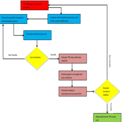
Figure 6. Flux diagram for material selection and analysis.
The sequence considered in this work is showed in Fig. 6, through a flux diagram, where one can see the material selection and the cost analysis. Obtaining this cost was the first obstacle to go ahead with the work, since some uncommon materials were selected. After the simulation the proposed configuration for TPS was considered validated, and showed lower cost, lower mass and a better performance than the current TPS design.
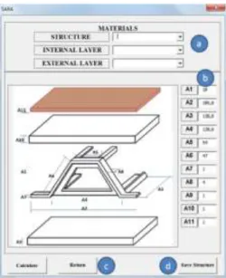
The software for simulation used in the economic viability analysis was built in Visual Basic for Applications (VBA). Its interface is showed in Fig. 7, where the inputs considered are listed (structure material, internal/external cover layer and TPS dimensions).
Materials considered for use in the proposed structure were Aluminum 2024 (Al 2024), Aluminum 7075 (Al 7075), Aluminum-Beryllium (Al-Be) and the composite Carbon fiber-Phenolic resin (CF). Such materials present excellent strength/weight ratio. Figure 8 presents material properties (Callister & Rethwisch, 2010). Both aluminium alloys are commonly used in aerospace industry and have high mechanical
strength and low weight. The Al-Be alloy is one of the lightest metallic material (only Mg has lower density) and presents higher strength than the Al alloys and consequently a high cost/benefit rate. The main advantages of the Carbon fiber are the very low density with high strength and the fact this material is not vulnerable to corrosion. However, it presents the highest costs and is the most difficult to manufacture, when compared with the previous metallic materials.
Figure 7. Interface of VBA software built for the analysis.
Density Tensile strength
Figure 8. Material properties.
Thermal insulation was provided by cork in the current configuration and Saffil® (alumina fiber) in TISSC. Both materials present low density and low thermal diffusivity. According with the previous work of Machado et al. (2013), their properties are 0.0242 g/cm³ and 0.9-0.12 W/m.K for Saffil® and 0.140 g/cm³ and 0.039-0.045 W/m.K for cork (UNIFRAX®, 2014; Gil, 2008).
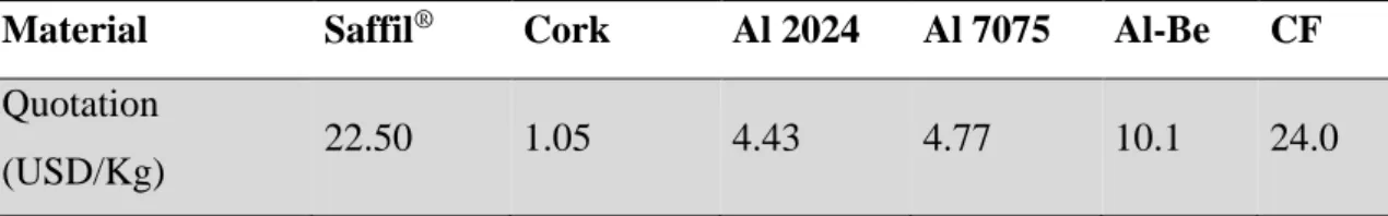
Material prices in USD/kg were obtained from diverse suppliers in Europe, Asia and USA. Three-five quotations for each material were considered, and used to obtain average values, showed in Table 1. In this work, taxes, political conditions for acquisition and depreciation were neglected.
Table 1. Average quotations for selected materials.
Material Saffil® Cork Al 2024 Al 7075 Al-Be CF
Quotation
(USD/Kg) 22.50 1.05 4.43 4.77 10.1 24.0
2. RESULTS
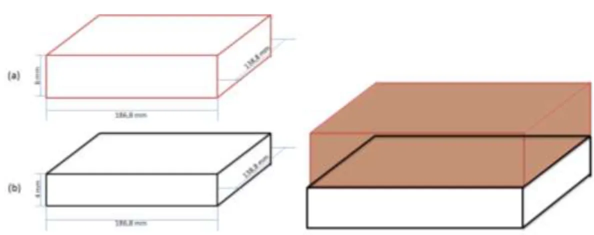
Dimensioning of the SARA according with the proposed TISSC protection was based on the previous work of (Martinez & Blosser, 2006). A unitary cell was used to generate the whole structure around the conic section. Figure 9 shows the adopted dimensions for every component and Fig. 10 shows the assembled elements in the cell. A cork layer with 1 mm thickness was included in the TISSC design, in order to avoid the external temperature of the structure overpasses the maximum limit allowed, as recommended in the previous work of (Damilano et al., 2015). In order to perform a straight comparison with the conventional TPS, an equivalent unitary cell was also created for this system, showed in Fig. 11. The resulting full TISSC structure, shown in Fig. 12, was modeled in three dimensions through the commercial software CATIA V5, where the material densities were extracted from After analysis, total mass and cost of the current configuration and the proposed configuration of TPS were compared, as showed in Figs. 13-14.
Figure 9. Adopted dimensions for the TISCC unitary cell: (a) cork, (b) structure, (b’) trusses and (c) Saffil®.
Figure 10. Assembled elements in the TISSC unitary cell.
Figure 11. Individual and assembled elements in the conventional TPS unitary cell. (a) cork layer and (b) metallic structure.
Figure 12. 3-D model of the proposed TPS configuration.
Results for the original TPS configuration are provided in Tabs.2,3. The results for TISSC configuration with all materials are shown in Tabs, 4-7.
Table 2. Volume, weight and cost of the current TPS – Al 2024 (unitary cell). Structure Cork layer Total
Volume (cm3) 103.71 155.57 259.28
Mass (g) 288.32 21.78 310.10
Cost (USD) 1.2758 0.0237 1.2995
Table 3. Volume, weight and cost of the current TPS – Al 7075 (unitary cell). Structure Cork layer Total
Volume (cm3) 103.71 155.57 259,28
Mass (g) 290.39 21.78 312.17
Cost (USD) 1.3842 0.0237 1.4079
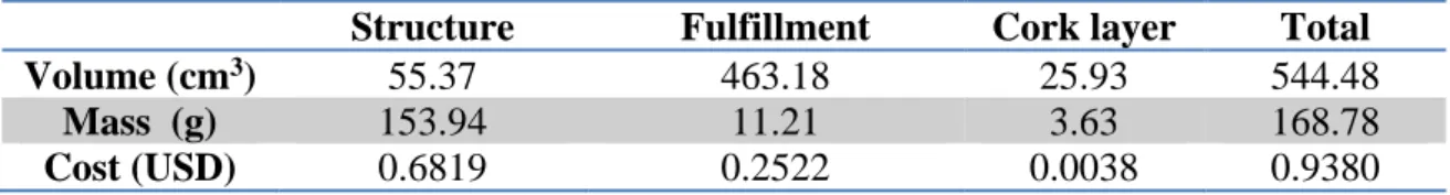
Table 4. Volume, weight and cost of proposed TISSC – Al 2024 (unitary cell).
Structure Fulfillment Cork layer Total
Volume (cm3) 55.37 463.18 25.93 544.48
Mass (g) 153.94 11.21 3.63 168.78
Cost (USD) 0.6819 0.2522 0.0038 0.9380
Table 5. Volume, weight and cost of proposed TISSC – Al 7075 (unitary cell). Structure Fulfillment Cork layer Total
Volume (cm3) 55.37 463.18 25.93 544.48
Mass (g) 155.05 11.21 3.63 169.88
Table 6. Volume, weight and cost of proposed TISSC – Al-Be (unitary cell). Structure Fulfillment Cork layer Total
Volume (cm3) 55.37 463.18 25.93 544.48
Mass (g) 120.16 11.21 3.63 135.00
Cost (USD) 1.2136 0.2522 0.0038 1.4696
Table 7. Volume, weight and cost of proposed TISSC – FC (unitary cell). Structure Fulfillment Cork layer Total
Volume (cm3) 55.37 463.18 25.93 544.48
Mass (g) 105.2092 11.21 3.63 120.0482
Cost (US) 2.5250 0.2522 0.0038 2.7810
CF
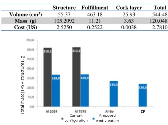
Figure 13. Mass variation according with the configuration proposed for every selected material.
Figure 14. Cost reduction according with the configuration proposed for every selected material.
According with results, a reduction of 45.56 % was obtained keeping the original materials (Al) and modifying the structure layout to the proposed configuration. When Al-Be and Carbon Fiber are used, the mass reduction rises to 56.46% and 61.30%, respectively. These reductions can be straight converted in cost reductions. However, when the final costs are compared, these materials present different results. Keep on using Al 2024 and Al 7075 results in a total cost reduction of 29% and 23%, respectively. These costs can be amortized with a higher quality manufacturing process, although this procedure could yield a higher initial cost.
Use of Al-Be results in a rising cost of 13 % when compared with the current configuration, even neglecting any additional cost related to manufacturing processes. Although Carbon fiber presented highest mass reduction, this material presents the highest cost, with an increment of 114 % when compared with the current configuration. This cost shall be even higher, considering that the manufacturing processes for this composite is more complex than the previous materials.
The mass reduction can be converted in payload increment, adding 15 to 20 kg plus to the 25 already available. According with (Corrêa & Moraes, 1999), the mass reduction can also extend the time available for microgravity experiments, adding 23 to 32 seconds. If such parameters (payload and microgravity environment time) were kept constant, the mas reduction can be converted in cost reduction, resulting in an economy of USD 15,000, which assures the economic viability of the proposed TPS configuration. Figures 15-16 summarizes the possible gains in every parameter according with the material selected. Such gains can be considered alone or in combination, according with the mission demands. Tables 8-10 summarize results for all materials.
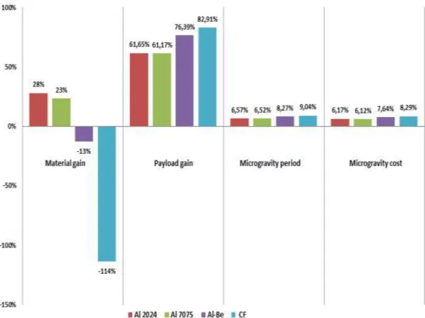
Figure 15. Summary of relative gains in every parameter.
Figure 16. Summary of total gains in every parameter.
Table 8. Mass variation according with material.
Mass current config(kg) 33.82 33.82 33.82 33.82 proposed config(kg) 18.41 18.53 14.72 13.09 Mass reduction (kg) 15.41 15.29 19.10 20.73 Total payload (kg) 40.41 40.29 44.10 45.73 Payload gain (%) 61.65 61.17 76.39 82.91
Table 9. Microgravity period according with material.
Al 2024 Al 7075 Al-Be CF Microgravity cost 10,000 10,000 10,000 10,000 Period of microgravity (min) 6.39 6.39 6.50 6.54 Increase in microgravity period (s) 23.65 23.46 29.77 32.55 Gain in time (%) 6.57 6.52 8.27 9.04
Table 10. Cost variation according with material.
Cost Al 2024 Al 7075 Al-Be CF
current config. (USD) 1.30 1.30 1.30 1.30
proposed config. (USD) 0.94 1.00 1.47 2.78
Cost reduction (USD) 0.36 0.30 -0.17 -1.48
Relative cost saving 28% 23% -13% -114%
Total cost saving (USD) 15,413 15,292 19,097 20,727
3. CONCLUSION
In this work, the economic viability of the use of a TISSC configuration to replace the conventional TPS of SARA sub orbital platform was studied. Since the technical viability was already verified and the dimensions to be considered were obtained from previous works, it was possible to estimate the gains due the mass reduction. These gains may consist in cost reduction or increasing of the payload or time of microgravity environment of the mission. In all cases, the manufacturing costs were not accounted.
If Aluminum is kept as structural material, both types used (Al 2024 and Al 7075) provide reduction in cost and mass, which confirms the economic viability of the proposed configuration. The best material seems to be Al-Be, since even considering
the manufacturing costs (due the fact this material is toxic when being processed) a reduction of 56.46% in mass was obtained, increasing the payload in 76.39 % when compared with the current configuration, resulting in USD 19,096.87 savings in the microgravity total cost. It should be emphasized the better processing characteristics of this material, when compared with both types of Al and the CF composite.
The Carbon Fiber composite shall provide a high mass reduction but also a high cost increasing. In this case, when manufacturing is accounted the cost rises greatly, since it can reach 1,000 EU/kg in an aerospace application. As an alternative, a re-dimensioning of the structure for CF composite could reduce the dimensions, and consequently, the cost for the use of this material, considering its high strength/weight ratio.
4. REFERENCES
CALLISTER, W. D. AND RETHWISCH, D. G. 2010. Materials Science and Engineering an introduction. 8 ed, United States, p.407-409;626-662.
CORRÊA, F. A. AND MORAES. P. Jr. 1999. Scientific and Technological Experiments in Microgravity Environments. XV Brazilian Congress of Mechanical Engineering - COBEM, Brasília, Brazil. (in Portuguese).
Damilano, J. G., Machado, H. A., AGUIAR, D. S., ALMEIDA, F. E., DUARTE, J. A. A. AND AZEVEDO, J. L. F., 2015. Configuration Study of Structurally Integrated Thermal Protection Systems for a Sub-Orbital Platform. J. Aerosp. Technol. Manag., São José dos Campos, Vol.7, No 2.
DefesaNET. 2014. MECTRON Supplies Equipments to SARA Suborbital Platform. 13 May 2015.
< http://www.defesanet.com.br>. (in Portuguese).
GIL, L. 2008. Cork – Production, Technology and Uses. Ed INETI, Lisbon, Portugal, p. 16-33. (in Portuguese).
MACHADO, H. A. AND LEITE, N. G. C. 2010. Two-dimensional simulation of ablation due to aerodynamic heating in the SARA sub-orbital platform. 13rd Brazilian Congress of Thermal Sciences and Engineering, Proceedings of ENCIT 2010. Uberlândia, Brazil.
MACHADO, H. A. AND VILLAS BOAS, D. J. F. 2006. Pressure Calculation in Surfaces Subjected to Aerodynamic Heating. Proceedings of the 11th Brazilian
Congress of Thermal Sciences and Engineering – ENCIT 2006. Braz. Soc. of Mechanical Sciences and Engineering - ABCM, Curitiba, Brazil.
MACHADO, H. A., PIRES, M., AMELOTI, G. B. AND MIRANDA, R. F. 2013. Structurally Integrated Thermal Protection Applied in The Sara Suborbital Platform. XXXIV CILAMCE, Pirenópolis, Brazil.
MACHADO, H. A., DÓREA F. T. AND MIRANDA, R. F. 2012. Simulation of ablation in a composite thermal protection system via an interface tracking method. Journal of Aerospace Technology and Management (Online), v. 4, p. 331-340.
MACHADO, H. A., SOUZA, C. E. AND MIRANDA, R. F. 2015. Thermal Performance Evaluation of TISSC Thermal Protection System in the Sara Sub-Orbital Platform. 23rd International Congress of Mechanical Engineering – COBEM, Rio de Janeiro, Brazil.
MARTINEZ, O. AND BLOSSER, M. 2006. Micromechanical Analysis of Composite Truss-core Sandwich Panels for Integral Thermal Protection Systems. 47th AIAA/ASME/ASCE/AHS Structures, Structural Dynamics, and Materials Conference, Newport.
MORAES Jr. P. 1998. Design Aspects of the Recoverable Orbital Platform SARA. Proceedings of 8th Chilean Congress of Mechanical Engineering. Concepcíon, Chile. POTEET C. C. AND HSU S. 2004. Preliminary Thermal-Mechanical Sizing of a Metallic Thermal Protection System. Journal Spacecraft & Rockets, v. 41, no. 2, p. 173-182.
Sandwich Panels for Integral Thermal Protection Systems. 47th AIAA/ASME/ASCE/AHS Structures, Structural Dynamics, and Materials Conference, Newport, May 2006.
SCHULZ AND MORAES JUNIOR, 2004. Re-entry trajectory simulation of a small ballistic recoverable satellite. Advances in space dynamics 4: celestial mechanics and astronautics. H. K. Kuga, Editor, 297-307, Instituto Nacional de Pesquisas Espaciais – INPE, São José dos Campos, SP, Brazil.
UNIFRAX®, 2014. “Ceramic Fibers UNIFRAX® for Thermal and Acoustic Insulation”. 18 Dec. 2014 <http://www.unifrax.com.br/>. (in Portuguese).