The Carbon Nanotubes Effect into Single-lap Joint Failure Modes and Load Capacity: a
Macromechanical Analysis
Elvis Carneiro Monteiroa*, Antonio Ferreira Avilab
Received: April 30, 2017; Revised: December 06, 2017; Accepted: December 08, 2017
This study investigates the influence of the adhesive (epoxy resin) thickness and the dispersions of non-functionalized carbon based nanostructures (carbon nanotubes - CNT) on mechanical properties of single-lap bonded joints. To achieve this goal, three CNT concentrations (0.5%, 1.0% and 2.0% m/m); and three different bondline thicknesses (0.05 mm, 0.15 mm and 0.40 mm) were evaluated. The mechanical properties were measured using the apparent shear tensile test, based on ASTM D5868. The results showed that the addition of 1.0 wt% CNTs improved the interface strength, leading to an increase on delaminated areas in failure region up to 55.36% and also improving the peak force up to 13.85%. Decrease in adhesive thickness from 0.40 mm to 0.05 mm promoted a stress redistribution inside adhesive layer improving the peak force up to 13.91%. CNT seems to promote changes in failure modes, light fiber tear (LFT) failure significantly increases up to 45.96%, indicating that interface strength between adhesive and adherent was improved.
Keywords: Bonded joints, nanocomposites, polymer, load capacity, carbon nanotubes.
*e-mail: [email protected].
1. Introduction
In recent years, the application of composite materials has been growing in many sectors of industry: civil engineering, aerospace, naval and automotive. Its main advantages are low density, high mechanical and corrosion resistance, the low cost of manufacture process and maintenance1. In most cases, traditional fastening methods (screws and rivets) may not be suitable for fiber reinforced composites. This is due to the stress concentration generated into the fibers/layers when holes are created for passing these fasteners. According to Wahab et al.2, adhesive joints are an interesting alternative for composites because their many advantages compared to traditional joints. Between them, weight and cost reduction, structural performance increase and fatigue resistance. The efficiency of bonded process is highly dependent of bonded area, adhesive strength and the quality of the adherent's surfaces. As commented by Cruz et al.3 and Banea and Silva4, bonded joints are frequently expected to sustain static or cyclic load for considerable periods of time without any adverse effect on the load-bearing capacity of the structure. They must hold a high stability towards a variety of mechanical, chemical and physical changes under service conditions. Many studies are developed in order to predicting possible failures in bonded joints. However, this is a difficult task due to the variations in joint's properties caused by the different manufacturing procedures. The effect of bondline thickness on the performance of various types of joints has been reported by several researchers over the years.
SLJs are widely used in industries to validate bonding solutions and have been studied extensively, however the effects of bondline thickness on the performance of single-lap joints is still a controversial issue (Akhavan-Safar et al.5). According Akhavan-Safar et al.5, numerical analysis
and classical analytical methods showed that joint strength increases when adhesive thickness increases due to more uniform strain and stress distribution along the adhesive layer, while experimental results showed that lap-joint strength decreases as the bondline thickness increases. Tamblin et al.6 studied several bondline thicknesses varying from 0.4 mm to 3 mm, using three types of adherents: Aluminum Alloy (2024-T3), carbon fabrics and glass fiber fabrics. They observed a decrease in the values of the peak shear stress with the increase of the adhesive thickness. Kahraman et al.7 investigated the influence of adhesive thickness on the single-lap joints properties. In their study, the thickness of the adhesive ranged from 0.03 mm to 1.3 mm, the adherents was made from aluminum and the adhesive was filled with aluminum powder. The results showed a decrease of 35-40% in joints shear strength, when bondline thickness increased from 0.03 mm to 1.3 mm. Park et al.8 proposed that thicker bondlines have more internal defects such micro-cracks and voids, which lead joints to early failures. Due difficult to determine the number and distribution of this defects, their hypothesis could not be validated. According to Grant et al.9 single-lap
joints under tensile stress are very sensitive to the thickness of the adhesive layer. As the adhesive layer increases, there is an increase in momentum under the overlap region due to eccentricity of the forces. Consequently the joint's strength
aUniversidade Federal de Minas Gerais, Programa de Pós-Graduação em Engenharia Mecânica, 31270-901, Belo Horizonte, MG, Brazil
bUniversidade Federal de Minas Gerais, Departamento de Engenharia Mecânica, 31270-901, Belo
decreases. Gleich et al.10 correlated the adhesive thickness influence in SLJs to the shear and peel stresses at interface and near the bondline end. In their analysis, the shear and peel stresses increases with increasing the bondline thickness, which could explain the effect of adhesive thickness in SLJs.
Epoxies resins are the polymeric systems most used as high-performance structural adhesive. As commented by Kahraman et al.7 epoxy resins are attractive for metal-bonding adhesive systems because of their ability to cure without producing volatile by-product and their low shrinkage upon cure. Epoxies, also are able to bond well to a variety of treated or untreated metal surface. In recent application, like aeronautic and aerospace industries, polymeric adhesives are often modified by adding fillers to enhance physical properties. Among the fillers, one of the most promising is the Carbon nanotubes or simply called CNT's.
The discovery of carbon nanotubes (CNT's) has opened vast areas of research in the nano-scale reinforcements for composites, in order to improve their mechanical, thermal and electrical properties. The CNTs was first reported in 1991 by Iijima et al.11 but reports of the existence of "worm-like" carbon structures date back to the 1950's, when Russian researchers observed the formation of long filaments of carbonic crystals with a diameter of approximately 50 nm in soot resulting from the decomposition of CO on iron particles at 600 ºC. Morphologically CNT can be compared to a graphene sheet rolled up, having at the end a hemispherical structure derived from a fullerene (C60).12 Commercially, single-wall carbon nanotubes (SWCNT) are found with diameters varying between 0.3 and 2.0 nm and with length up to 50 µm.13 Despite the difficulty in manipulating objects on a nanometric scale, several articles in the literature report direct experimental measurements of the Young's modulus of CNTs.14 Treacy et al.15 concluded in their experiments
that the modulus of elasticity SWCNTs ranges from 0.9 to 1.9 TPa. Krishman et al.16 reached results of 1.3_0.4 TPa. Hernandez et al.17 obtained values of 1.24 TPa. Popov et al.18 found values close to 1.0 TPa. The great variability of the results can be attributed to the forms of measurement and the difficulty of handling such small structures. Multi-wall carbon nanotubes MWCNTs can be considered as a set of concentric SWCNTs with different diameters. For MWCNTs, studies show different results to those found for SWCNTs due to the interaction between the various concentric tubes (Van der Waals forces). Natsuki et al.19 obtained values of
0.8 to 1.6 TPa for elasticity modulus of MWCNTs. Different values obtained by Wong et al.20 who in his study found 1.28 -0.59 TPa.
Thostenson et al.21 pointed out the advantages of dispersing CNT into epoxy systems. Gojny et al.22 tested the behavior of epoxidized resins reinforced with functionalized and non-functionalized nanotubes. According to their results, a 43% increase in the fracture strength of the resin was observed with the addition of 0.5% of functionalized nanotubes (MWCNTs).
In another work, Gojny et al.23 have shown through their study that epoxy/fiberglass composites modified by the addition of 0.3 wt% MWCNTs-NH2 (amino-functionalized) have delamination resistance 19% higher than traditional composite. Godara et al.24 observed an increase in crack initiation energy
(GIc) up 75% in MWCNT-epoxy system with a compatibilizer compared to the benchmark carbon epoxy system. Davis et al.25 tested carbon fiber reinforced epoxy composite with
different amounts of fluorine functionalized CNTs. Their results showed that sample with 0.5wt. % f-CNT showed an average increase of 18% in strength and 24% in stiffness, compared against neat material. Ashrafi et al.26 performed impact and compression-after-impact (CAI), Mode I and Mode II Interlaminar fracture toughness tests in modified epoxy resin filled with different quantities of functionalized single-wall nanotubes. They found that addition of 0.1 wt. % of SWCNT resulted in a 5% reduction of damage in impact area, a 3.5% increase in CAI strength, a 13% increase in Mode I and 28% in Mode II of fracture toughness.
This study investigates the influence of the adhesive thickness and the dispersions of carbon based nanostructures (carbon nanotubes-CNT) on mechanical properties of single-lap bonded joints. Experiments were performed on SLJs with three different bondline thickness and three different concentrations of CNT dispersed into the polymeric system used as adhesive. Joint strength, failure modes and CNT dispersion were evaluated.
2. Experimental Procedures
The adherents were manufactured using a plain weave glass fiber fabric (300 g/m2) and an epoxy system supplied by Huntsman Inc (RenLam M and HY956). The mixing ratio was 100 parts of resin to 20 parts of hardener and the gel time is 30 minutes at 25 º C. The final resin has a density of 1.1 g /cm3. The cure was performed for 24 hours at room temperature and post cure for 6 hours at 60 ºC. The adherents were made using the ratio of 60% fiber and 40% resin. The composite plates were made in 250 mm x 250 mm, all of them consisting of 9 layers of fibers, leading to an average thickness of 2.37 mm. To obtain the final dimensions of the adherents and tabs (in accordance with ASTM-D5868), the plates were cut and sanded (using sandpaper grit 50 and 300).
The weight ratios of the carbon nanotubes/epoxy resin were set to 0 wt%, 0.5 wt%, 1.0 wt%, 2.0 wt%, Table 1 lists the test groups developed. Based in Munhoz29, an
ultrasonic bath Norking at 42 kHz and 160 W was used to disperse the CNTs into resin. In his work, Munhoz29 used the
same ultrasonic bath for 15 min and achieved good results at concentrations of nanostructures up to 0.3 wt% (CNT, graphene, CNT + graphene). Due to the high concentrations used in this work, mixture resin/CNT was sonicate for 80 min. Each cycle of the ultrasonic bath has 8 minutes on and another 1 minute to restart a new cycle. To help control the temperature of the mixture, cooled water and ice cubes were used around the beaker. Every two cycles the water used to cool the mixture was replaced. The mixture temperature was kept in 35ºC, monitored with a thermometer.
The hardener was manual mixed in the solution of resin and MWCNT. The adherents were sanded with 200 grit sandpaper (overlap region only) to increase surface roughness, and then, cleaned with acetone. The specimens were bonded using a device developed to maintain the alignment of joints. The adhesive was cured for 24 hours at room temperature and post cure was performed for 6 hours at 80 º C. Atomic Force Microscopy (AFM) analyses were conducted to verify the quality of CNT dispersion into polymeric system.
The mechanical tests were performed according to the specifications of Standard ASTM-D5868 in load frame testing. The displacement velocity of the head was set at 13 mm /min. The load cell has a maximum capacity of 100 kN. The obtained data were exported to other software for the accomplishment of calculations, generation of the graphs and data analysis. The damage areas were measured using the ImageJ, an image processing and analysis software.
3. Results and Discussions
Two different approaches can be employed during data analysis. The first one was considering how the bonded joint ultimate load and the failure modes were related to the carbon nanotube quantities dispersed into the epoxy system. The second approach focused on adhesive thickness effects into the bonded joint load capacity.
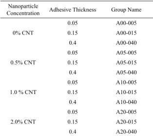
Analyzing the influence of CNT addition on joint mechanical behavior, the best results was observed in the samples with adhesive thickness of 0.15 mm. In this groups a significant change occurred in failure mode with the increase of CNT concentration. In the tested samples, the addition of CNT in epoxy adhesives promote an increase in delaminated areas during failure process in samples tested, called light fiber tear (LFT), as could be observed in figure 1. Standard ASTM 557330 describes the light fiber tear (LFT) as a failure occurring within the substrate, close to the surface, characterized by tearing the surface layer of matrix, completely or partially exposing the reinforcement fibers. Figure 2 shows a diagram of a LFT failure. Figure 3 shows the Figure 3(b) showed that samples with 0.0 wt% of CNT (group A00-015) have an LFT failure area corresponding of 61.72% from the total failure region. This value was increase up to 77.89% for samples with 0.5 wt% CNT (group A05-015), 95.89% for samples with 1.0 wt% CNT (group A10-015) and 92.23% for samples with 2.0 wt. % CNT (group A20-015). It was observed an increase in load capacity up to 13.85% for group with 1.0 wt. % CNT (group A10-015), compared against group with pure epoxy adhesive. Similar effect was observed in figure 3(a) for adhesive thickness of 0.05 mm and figure 3(c) for 0.40 mm. For all three bondline thickness tested, the LFT failures and load capacity increase with increasing CNT concentration up to 1.0 wt%. At concentrations exceeding this value, this parameters begin to decrease, in some cases, to levels below that of the pure epoxy, as observed in figure 3(c).
Similar results was found by Wernick et al.31 In their study, mechanical properties of carbon nanotubes reinforced epoxy adhesives were investigated experimentally. Their results indicated that largest improvements occurs between 1.0 wt% and 1.5 wt% of CNT. At higher concentrations, exceeding these values, the properties begin to degrade. They hypnotized that this phenomena occurs mainly due to the agglomeration of CNTs at high concentrations. They observed increases of 50% and 500% in the size of agglomerations when CNT concentration increased from 1.0 wt% to 2.0 wt% and 3.0 wt%, respectively. The tendency to form CNT agglomerates due the increase in concentration dispersed was also reported by Munhoz29.
Table 1. Test Groups Nanoparticle
Concentration Adhesive Thickness Group Name
0% CNT 0.05 A00-005 0.15 A00-015 0.4 A00-040 0.5% CNT 0.05 A05-005 0.15 A05-015 0.4 A05-040
1.0 % CNT
Figure 1. Failure modes for groups with 0.15 mm of thickness. (a) Group A00-015; (b) Group A05-015; (c) Group A10-015; (d) Group A20-015. Areas in red indicating the LFT failures.
Figure 2. Diagram of a light-fiber tear failure.
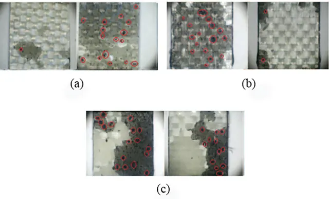
To evaluate the dispersion of CNTs into epoxy system, atomic force microscopy (AFM) analysis was performed. The AFM analyses in figure 4 showed the CNT distribution inside the adhesive for all three concentration. As could be observed, with the increase of CNT amount dispersed in epoxy adhesive, agglomerates begin to form. This phenomena can be observed macroscopically in figure 5, where black dots in failure area seems to be CNT agglomerates. These black dots seems to be randomly dispersed and their size increases with CNT concentration. For 0.5 wt.% CNT concentration (group A05-015) the average diameter for these agglomerates was 0.24 mm, this value increased to 0.29 mm and 0.32 mm for groups with 1.0 wt. % CNT (A10-015) and 2.0 wt.% CNT (A20-015), respectively. Agglomerates usually act as stress concentrators, reducing the overall capacity of CNT to improve mechanical properties.
These changes in failure modes and also load capacity, could be related to the stress redistribution caused by the dispersion of CNT. The CNT may have interacted with the polymer chains creating a mechanical barrier, reducing the nucleation and propagation of cracks. This interaction could be provide a better surface adhesion between adhesive and adherent, creating a stronger interface32. Sydlik et al.32 observed the presence of different surface morphology along the crack if CNT are present in the adhesive. At microscopic level the fracture surface roughness was observe to increase with the increasing lap shear strength, suggesting less facile crack propagation. At macroscopic level their failure mode was primarily adhesive failure. Since the crack propagated across the epoxy as it transferred once from one face to the other, they hypothesized that CNT deflected the crack as it propagated through the adhesive layer, promoting an increasing in joint strength.
Figure 3. Peak force and LFT failure percentage: (a) Thickness: 0.05 mm; (b) Thickness: 0.15 mm; (c) Thickness: 0.40 mm
Figure 5. CNT agglomerates visible on failure region: (a) Group A05-015; (b) Group A10-015; (c) Group A20-015.
Figure 7. Failure modes for pure adhesive. (a) Group A00-005; (b) Group A00-015; (c) Group A00-040. Areas in red indicating the LFT failures.
Figure 8. Failure modes for adhesive + 0.5 wt% CNT. (a) Group A05-005; (b) Group A05-015; (c) Group A05-040. Areas in red indicating the LFT failures.
A00-005. According Budhe et al.33, this behavior could be related to two main factors: redistribution of stress inside the adhesive layer and the number of internal defects, such voids, which increases with the adhesive layer.
Figure 9. Failure region for groups with 0.05 mm: (a) Group A10-005; (b) Group A10-015; (c) Group A10-040
Table 2. Mechanical properties and percentage delaminated area
Peak Force (N)
CNT concentration (wt. %) Thickness (mm) Group ID Average value Std. Dev. Delaminated Area (%)
0.0
0.05 A00-005 7104.49 226.60 66.46
0.15 A00-015 6937.63 250.93 63.73
0.40 A00-040 6236.96 180.19 55.22
0.5
0.05 A05-005 7531.35 305.46 70.99
0.15 A05-015 7310.68 145.27 77.89
0.40 A05-040 6608.76 207.56 57.70
1.0
0.05 A10-005 7710.68 201.89 84.23
0.15 A10-015 8053.26 150.32 95.86
0.40 A10-040 6653.26 289.03 59.19
2.0
0.05 A20-005 6328.07 194.85 80.64
0.15 A20-015 7250.68 241.96 92.23
0.40 A20-040 5185.29 124.03 51.16
to 84.22% (group A05-005), with decrease in adhesive thickness. Comparing the results between pure adhesive and adhesive with 0.5 wt.% CNT, the addition of CNT promote an increase in delaminated area to all bondline thickness tested.
Groups with 1.0% and 2.0% showed best results in adhesive thickness of 0.15 mm instead 0.05 mm, as observed in figure 6(c) e figure 6(d), respectively. Samples with 1.0% CNT and 0.15 mm of adhesive layer (A10-015) showed 95.86% of LFT failure and a peak shear stress 57.12% higher than samples with 0.40 mm (A10-040). This behavior could be linked to an increase in number of agglomerates observed in samples
with 0.05 mm, with increasing CNT concentration. In figure 9, the CNT agglomerates seems randomly dispersed and their average diameter increases from 0.26 mm in group A05-005 to 0.32 mm in group A10-005 and 0.38 mm in group A20-005.
Table 2 summarizes the mechanical strength and percentage delaminated area for all groups tested.
4. Conclusion
in delaminated areas (LFT). Groups with bondline thickness of 0.15 mm, showed a relative increase of 55.36%, when delaminated areas changed from 61.72% of failure region in group A00-015 (pure adhesive) to 95.89% in group A10-015 (adhesive + 1.0% CNT). Also an improvement of 13.85% in peak force was reported in group with 1.0 wt% CNT. These effects could be associated to interactions between CNT and polymeric chains leading to formation of a mechanical barrier, reducing the nucleation and propagation of cracks and improving the adhesion between adhesive and adherent. The presence of CNT agglomerates in some samples could be reduce the CNT capacity of improve mechanical properties.
Decrease in adhesive thickness showed influence in peak force and also in failure modes. Improvements in peak force over 13.91% was observed when bondline thickness was reduced. In same case an increase in delaminated areas up to 45.96 % also was observed. This effect could be related to the redistribution of stress inside overlap region due to bondline thickness decrease.
5. Acknowledgments
The authors are grateful to the Coordination for the Improvement of Higher Education Personnel (CAPES) and Department of Mechanical Engineering of Universidade Federal de Minas Gerais for the support in this research.
6. References
1. Gouda SPS, Kulkarni R, Kurbet SN, Jawali D. Effects of multi walled carbon nanotubes and graphene on the mechanical properties of hybrid polymer composites. Advanced Materials Letters. 2013;4(4):261-270.
2. Wahab MMA, Ashcroft IA, Crocombe AD. A comparison of failure prediction methods for an adhesively bonded composite beam. Journal of Strain Analysis for Engineering Design.
2004;39(2):173-185.
3. Cruz TDL, Silva Neto A, Avila AF. Nano-Modified Adhesives By Graphene: The Effect Ageing Investigation. In: Proceedings of 54th AIAA/ASME/ASCE/AHS/ASC Structures, Structural Dynamics, and Materials Conference; 2013 Apr 8-11; Boston,
MA, USA.
4. Banea MD, Silva LFM. Adhesively bonded joints in composite materials: an overview. Journal of Materials Design and Applications. 2009;223:1-18.
5. Akhavan-Safar A, Ayatollahi MR, da Silva LFM. Strength prediction of adhesively bonded single lap joints with different bondline thickness: A critical longitudinal strain approach.
International Journal of Solids and Structures.
2017:109:189-198.
6. Tamblin JS, Yang C, Harter P. Investigation of Thick Bond Line Adhesive Joints. Washington: U.S. Department of Transportation/
Federal Aviation Administration; 2001.
7. Kahraman R, Sunar M, Yilbas B. Influence of adhesive thickness and filler content on the mechanical performance of aluminum single-lap joints bonded with aluminum powder filled epoxy adhesive. Journal of Materials Processing Technology.
2008;205(1-3):183-189.
8. Park JH, Choi JH, Kweon JK. Evaluating the strengths of thick aluminum-to-aluminum joints with different adhesive lengths and thicknesses. Composite Structures. 2010;92(9):2226-2235.
9. Grant LDR, Adams RD, da Silva LFM. Experimental and numerical analysis of single lap joints for the automotive industry. International Journal of Adhesion & Adhesives. 2008;29(4):405-413.
10. Gleich DM, Van Tooren MJL, Beukers A. Analysis and evaluation of bondline thickness effects on failure load in adhesively bonded structures. Journal of Adhesion Science and Technology. 2001;15(9):1091-1101.
11. Iijima S. Helical microtubules of graphitic carbon. Nature.
1991;354:56-58.
12. Pereira GC. Nanocompósitos híbridos modificados com nanotubos de carbono: síntese e caracterização. [Dissertation].
Belo Horizonte: Universidade Federal de Minas Gerais; 2013. 13. Kang I, Heung YY, Kim JH, Lee JW, Gollapudi R, Subramaniam
S, et al. Introduction to carbon nanotube and nanofiber smart materials. Composites Part B: Engineering. 2006;37:382-394.
14. Prasek J, Drbohlavova J, Chomoucka J, Hubalek J, Jasek O, Adam V, et al. Method for carbon nanotubes synthesis - review.
Journal of Materials Chemistry. 2011;21(40):15872-15884.
15. Treacy MMJ, Ebbesen TW, Gibson JM. Exceptionally high Young's modulus observed for individual carbon nanotubes.
Nature. 1996;381:678-680.
16. Krishman A, Dujardin E, Ebbesen T, Yianilos PN, Treacy PYM. Young's modulus of single-walled nanotubes. Physics Review B. 1998;58(20):14013-14019.
17. Hernandez E, Goze C, Bernier P, Rubio A. Elastic Properties of C and BxCyNz Composite Nanotubes. Physics Review Letters.
1998;80(20):4502-4505.
18. Popov V, van Doren VE, Balkanski M. Elastic properties of single walled carbon nanotubes. Physical Review B. 2000;61(4):3078-3084.
19. Natsuki T, Tantrakarn K, Endo M. Effects of carbon nanotubes structures on mechanical properties. Applied Physics A.
2004;79(1):117-124.
20. Wong EW, Sheehan PE, Lieber CM. Nanobeam Mechanics: Elasticity, Strength, and Toughness of Nanorods and Nanotubes.
Science. 1997;277(5334):1971-1975.
21. Thostenson ET, Li C, Chou TW. Nanocomposites in context.
Composite Science and Technology. 2005;65:491-516.
22. Gojny FH, Wichmann MHG, Fiedler B, Bauhofer W, Schulte K. Influence of nano-modified on the mechanical and electrical properties of conventional fibre-reinforced composites. Composites Part A: Applied Science and Manufacturing. 2005;36(11):1525-1535.
24. Godara A, Mezzo L, Luizi F, Warrier A, Lomov SV, van Vuure AW, et al. Influence of carbon nanotube reinforcement on the processing and the mechanical behavior of carbon fiber/epoxy composites. Carbon. 2009;47(12):2914-2923.
25. Davis DC, Wilkerson JW, Zhu J, Ayewah DOO. Improvements in mechanical properties of a carbon fiber epoxy composite using nanotube science and technology. Composite Structures.
2010;92(11):2653-2662.
26. Ashrafi B, Guan J, Mirjalili V, Zhang Y, Chun L, Hubert P, et al. Enhancement of mechanical performance of epoxy/carbon fiber laminate composites using single-walled carbon nanotubes.
Composites Science and Technology. 2011;71(13):1569-1578.
27. Barracuda Advanced Composites. Standard product specification AR-300. Technical Data Sheet; 2015.
28. Ferlauto AS, de Florio DZ, Fonseca FC, Esposito V, Muccillo R, Traversa E, et al. Chemical vapor deposition of multi-walled carbon nanotubes from nickel/yttria-stabilized zirconia catalysts.
Applied Physics A. 2006;84(3):271-276.
29. Munhoz VC. Funcionalização não covalente de nanotubos de carbono e grafeno para aplicação em compósitos carbono/ epóxi. [Dissertation]. Belo Horizonte: Universidade Federal
de Minas Gerais; 2016.
30. ASTM International. ASTM D5573-99 (2012) - Standard Practice for Classifying Failure Modes in Fiber-Reinforced-Plastic (FRP) Joints. West Conshohocken: ASTM International;
2012.
31. Wernik JM, Meguid SA. On the mechanical characterization of carbon nanotube reinforced epoxy adhesives. Materials & Design. 2014;59:19-32.
32. Sydlik SA, Lee JH, Walish, JJ, Thomas EL, Swager TM. Epoxy functionalized multi-walled carbon nanotubes for improved adhesives. Carbon. 2013;59:109-120.
33. Budhe S, Banea MD, de Barros S, da Silva LFM. An updated review of adhesively bonded joints in composite materials.
International Journal of Adhesion and Adhesives.