DOI: 10.1590/S1516-14392011005000059
*e-mail: [email protected]
Enhanced Electrochemical Activity Using Vertically Aligned Carbon Nanotube
Electrodes Grown on Carbon Fiber
Evandro Augusto de Morais*, Gaston Alvial, Rafael Longuinhos, Jose Marcos Andrade Figueiredo,
Rodrigo Gribel Lacerda, Andre Santarosa Ferlauto, Luiz Orlando Ladeira
Departamento de Física, Universidade Federal de Minas Gerais – UFMG,
CEP 31270-901, Belo Horizonte, MG, Brazil
Received: April 11, 2011; Revised: July 8, 2011
Vertically aligned carbon nanotubes were successfully grown on flexible carbon fibers by plasma enhanced chemical vapor deposition. The diameter of the CNT is controllable by adjusting the thickness of the catalyst Ni layer deposited on the fiber. Vertically aligned nanotubes were grown in a Plasma Enhanced Chemical Deposition system (PECVD) at a temperature of 630 °C, d.c. bias of –600 V and 160 and 68 sccm flow of ammonia and acetylene, respectively. Using cyclic voltammetry measurements, an increase of the surface area of our electrodes, up to 50 times higher, was observed in our samples with CNT. The combination of VACNTs with flexible carbon fibers can have a significant impact on applications ranging from sensors to electrodes for fuel cells.
Keywords: vertically aligned carbon nanotubes, plasma enhanced chemical vapor deposition, cyclic voltammetry
1. Introduction
Carbon nanotubes (CNTs) have specific physical and chemical properties, such as high electrical conductivity, high ratio aspect and high mechanical resistance, becoming a promising material for applications in a wide variety of fields1,2. In particular, the combination
of its high conductivity and high surface area makes CNTs very attractive to be used as electrodes in electrochemical applications as well as electron field emission sources3-8. Specially, CNTs and carbon
nanofibers (CNFs) have become key materials as electrodes in proton exchange membranes (PEM) fuel cells6-15. For instance, the intrinsic
properties of carbon fibers such as high flexibility, mechanical and chemical stability can ensure a higher durability, versatility and lifetime of the electrode11,13. For instance, Maheshwari et al. have
demonstrated the best performance in PEM fuel cell with CNTs coated onto carbon fibers8. Recently, supports using carbon fibers
and carbon nanotubes have been used as electrodes in PEM fuel cells in order to overcome some issues related to carbon black supports. These limitations include mass transport at high current densities, due to dense structure of carbon black, and its susceptibility to hostile work environments of the PEM fuel cells11. Also, importantly, the
possibility to improve cell efficiency and to promote cost reduction by decreasing the Pt catalyst loading is one of main advantages of the carbon fiber/paper-based electrodes9. Besides that, the interactions
between the gases with the catalysts nanoparticles on the external wall of the CNTs are more efficient than those interactions at the internal porous of carbon black12. Another advantage related with
the growth of CNTs on CFs, is the direct electron conduction due to the weak interaction between the deposited catalyst and the carbon substrate15. Additionally, a higher electron emission was
also observed in CNT grown on carbon fibers compared to CNT on Si, revealing that multiwalled carbon nanotubes (MWCNTs) on carbon fibers has a great potential for emission displays5. However,
the growth of VACNTs on carbon fibers still has not been deeply explored16-18 as observed on Si and other substrates19-21. VACNTs
have some advantages when compared with the ones grown without
any orientation. One of the most important is the lack of interaction between neighbor tubes, allowing the full exploration of the entire surface area of the CNTs as well as a more efficient and stable electron emission16,18. It is also to be expected that the fact that the nanotubes
are vertically aligned would provide a more efficient coverage of its surface with Pt nanoparticles catalysis, and hence, improve the efficient of the PEM fuel cells22. In this context, we present in this
work a systematic study of VACNTs directly grown on carbon fibers by plasma enhanced chemical vapor deposition (PECVD). Scanning electron microscopy images of our grown material are presented. Cyclic voltammograms were also performed to asset the improved performance of CNTs grown on the carbon fibers.
2. Experimental
Commercially available hydrophobic carbon cloths (fibers) coated with PTFE, roughly 8.3 µm width, 1.75 g.cm–3 of density and 0.33 mm
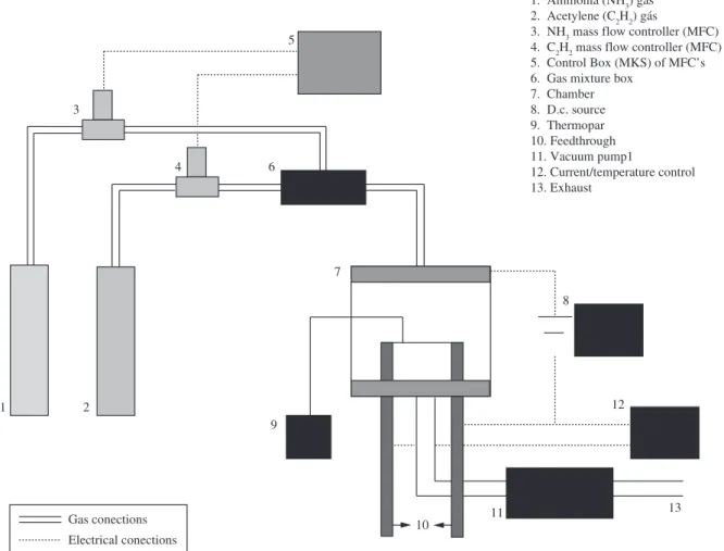
of thickness were used as flexible substrate to promote CNT growth. Here, CF names the non-treated carbon fiber and VACNT names the vertically aligned carbon nanotubes grown on carbon fibers by PECVD using Ni as catalyst particles. The synthesis process follows the same procedure described elsewhere23,24 (see schematic diagram
in Figure 1). Initially, the fiber was covered with a layer of Nickel via thermal evaporation at 10–6 Torr. Then, we heated the sample
(CF) with the previously desired thickness of Ni, in a low vacuum (5 × 10⁻² Torr) chamber at 160 sccm ammonia flow. A d.c. bias of
the carbon fibers without nanotubes resulting in a poor coverage, i.e., the quantity of nanotubes per area. Besides this, the growth time was not sufficient to reach the maximum expected length of the nanotubes. By increasing the reaction time to 30 minutes, an improvement of the growth can be observed, as can be seen in Figure 3b. In spite of the fact that a higher density was obtained, still some non-uniformity can still be seen on the fiber surface. This behavior can be attributed to a non-homogenous Ni layer deposited on the CF and/or inefficient Ni-island formation (less than 100 nm of diameter) during annealing that was done before the plasma growth process, where probably the Ni-island does not reach the catalytic condition. SEM images, showed in Figure 3c, reveal that after 40 minutes of growth the best condition were reached. These conditions obtained lengths up to 3 µm and a
forest of well aligned nanotubes, despite unfavorable conditions for CNT grown on porous carbon fibers which are often tangled25.
on the fiber is dependent upon the time of the reaction. Using this procedure we prepared six samples with different Ni layers and reaction times. Sample identification and their preparation parameters are shown on Table 1.
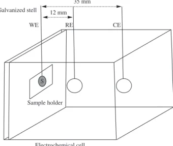
For all samples, scanning electron microscopy (SEM) images of both CF and VACNT samples were taken with FEG – FEI – 2006 microscope (voltage 200 V-30 kV) equipped with energy-disperse secondary analysis system (EDS). In order to verify the electrochemical efficiency of our samples we performed voltammetric cycles using an Autolab PGSTAT 20 Potentiostate/Galvanostate. For this, a homemade cell was build using a platinum plate as counter electrode and Ag/AgCl as a reference electrode. All sampled were tested in H2SO4 0.1 M between 0.2 and 0.8 V at 20 mV/s. Working electrode area for all experiments was 0.55 cm2. More details are
presented in Figure 2. It is important to mention that, for the same sample, after 8 cycles all voltammograms were overlapped. For this reason, the analyses shown in this paper were carried out after 8 cycles of voltammograms.
3. Results
3.1. Morphology analysis
Figure 3 shows the images obtained by SEM of samples 2.a, 2.b and 2.c, which show the effect of the growth time on the synthesis of a VACNT. Figure 3a shows the growth of VACNTs after a reaction time of 20 minutes. It is to be noted that there is still a considerable area of
Figure 1. Schematic diagram for growth of vertically aligned carbon nanotubes (VACNT) by PECVD.
Table 1. Sample identification list and synthesis parameters.
Sample number
Ni thickness (nm)
Reaction time (minutes)
Temperature of synthesis (°C)
1 8 40 630
2.a 15 20 630
2.b 15 30 630
2.c 15 40 630
Figure 2. Schematic diagram of electrochemical cell: WE – working electrode, RE – reference electrode and CE – counter electrode.
Figure 3. SEM images of VACNT for: a) 20 minutes; b) 30 minutes; and c) 40 minutes growth times.
Figure 4. SEM images of VACNT on treated samples for different Ni thickness: a) 8 nm; b) 15 nm; and c) 30 nm.
Based on this initial synthesis study, the samples from now on will be produced at this condition, but with different Ni thickness. It is well known that the catalyst layer has an important influence on the growth, allowing the control of the CNT diameter and density26.
SEM micrograph images shown in Figure 4a, b and c are related to
three different Ni thicknesses: 8, 15 and 30 nm (see Table 1). As can be observed, the Ni thickness is directly related to the diameter of the CNTs. Also, Ni particles are presented at the top of the nanotubes which indicates the occurrence of top-growth method. SEM analysis indicates an average diameter of about 25 nm for sample 1, 60 nm for sample 2.c and 140 nm for sample 3. Along each sample, there is a distribution of CNTs diameters and length due to non-uniformity of Ni deposition on porous fibers.
3.2. Electrochemical study
process and because it is a measure of the deviation of reversibility that characterizes slow kinetics at the electrode. In other words, an increase in the active surface area is conveyed by a larger internal area of the voltammetric curve. Values for the internal area of the voltammograms curves as function of Ni diameter on top of nanotube are presented in Table 2.
The surface area of carbon nanotubes samples is directly related to the average diameter of the tubes9. For isolated or well
separated nanotubes, larger diameters correspond to smaller surface area and consequently to lower charge transfer in CNT-based electrodes. However, for electrodes with highly entangled nanotubes, this correlation does not necessarily hold. Ionic species within the electrolyte may not have complete access to the entire CNT electrode surface28. In our samples, we have observed increase
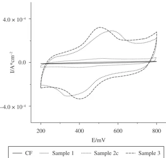
in charge transfer for treated samples in relation to non-treated (see Figure 5 and Table 2). For sample 1, a ~5× times increase in charge transfer is observed as compared to untreated carbon fiber sample (without nanotubes). However, when the CNTs diameter is increased (sample 2.c), a significant ~50× times enhancement in the electrochemical activity is observed, as compared with the untreated fiber sample. Although it is expected that CNT with a smaller diameter are likely to be more electrochemically active29,
our results show an increase in electrochemical activity for CNT with larger diameter. However, the CV measurements are made in aqueous medium and the surface tension promotes the agglomeration/ collapse of CNTs, as shown in Figure 6. It is reasonable to assume that the degree of this agglomeration is inversely proportional to the diameter. In other words, a larger diameter would result in a smaller degree of agglomeration. So, sample 3 has a more effective charge transfer than sample 2.c that, in turn, has a better charge transfer than sample 1. This collapse of small diameter CNT is an undesirable effect due to the blocking of the CNT surface, making it less sensitive to electrochemical activity16,30.
pH of the solution. In order to guarantee the presence of nanotubes in samples investigated, new SEM images were carried out after voltammetric study, Figure 6. These images now present bundles of nanotubes, forming an agglomerated cusp at the top, probably due to the surface tension associated to the presence of water in the sample. Similar images were observed by Ye et al16.
For the non-treated electrode case, the voltammograms show a quasi linear profile, with small cycle area and no peaks produced. This means that, in this case, charge transfer processes are slow, indicating no relevant electrochemical activity. Conversely, treated electrodes present a classical behavior and shape. Due to the large cycle area, these curves clearly illustrate the catalyst behavior of the VACNT. At small voltage values in the forward part of the voltammetric cycle the current grows exponentially, indicating a strong electrochemical activity, which could be associated to fast charge transfer processes. We have shown in Figure 4 that the average diameter of the nanotubes is determined by the thickness of the catalyst Ni layer. It is then to be expected that changes in the CNT diameter would promote changes in the active surface of the samples (VACNTs), and consequently, on its electrochemical activity. In fact, the internal areas of the curves in Figure 5 are related to the efficiency of the charge transfer
Table 2. Internal area of cyclic voltammograms for non-treated and treated samples as function of Ni thickness.
Samples Ni thickness (nm)
CNT diameter (nm)
Cycle area (mC.cm–2)
CF - - 0.2
VACNT
8 25 1.6
15 60 9.8
30 140 11.0
Figure 5. Cyclic Voltammetry for non-treated and treated samples as function of Ni thickness.
13. Wallnofer E, Perchthaler M, Hacher V and Squadrito G. Optimisation of carbon nanofiber based electrodes for polymer electrolyte membrane fuel cells prepared by a sedimentation method. Journal of Power Sources. 2009; 188:192-198. http://dx.doi.org/10.1016/j.jpowsour.2008.11.052
14. Bessel CA, Laubernds K, Rodriguez NM and Baker RTK. Graphite Nanofibers as an Electrode for Fuel Cell Applications. The Journal of Physical Chemistry B. 2001; 105:1115-1118. http://dx.doi.org/10.1021/jp003280d
15. Huang C, Chuang C, Ting J and Teng H. Significantly enhanced charge conduction in electric double layer capacitors using carbon nanotube-grafted activated carbon electrodes. Journal of Power Sources. 2008; 183:406-410. http://dx.doi.org/10.1016/j.jpowsour.2008.04.075
16. Ye XR, Chen LH, Wang C, Aubuchon JF, Chen IC, Gapin AI et al. Electrochemical Modification of Vertically Aligned Carbon Nanotube Arrays. Journal of Physical Chemistry B. 2006; 110:12938-12942. PMid:16805595. http://dx.doi.org/10.1021/jp057507m
17. Chen LH, AuBuchon JF, Chen IC, Daraio C, Ye XR, Gapin A et al. Growth of aligned carbon nanotubes on carbon microfibers by dc plasma-enhanced chemical vapor deposition. Applied Physics Letters. 2006; 88:033103(1-3). http://dx.doi.org/10.1063/1.2166472
18. Caillard A, Christine Charles C, Boswell R, Brault P and Coutanceau C. Plasma based platinum nanoaggregates deposited on carbon nanofibers improve fuel cell efficiency. Applied Physics Letters. 2007; 90:223119(1-3).
19. Melechko AV, Merkulov VI, McKnight T E, Guillorn MA, Klein K L, Lowndes D H et al. Vertically aligned carbon nanofibers and related structures: Controlled synthesis and directed assembly. Journal of Applied Physics. 2005; 97:041301. http://dx.doi.org/10.1063/1.1857591
20. Chhowalla M, Teo KBK, Ducati C, Rupesinghe NL, Amaratunga GAJ, Ferrari AC et al. Growth process conditions of vertically aligned carbon nanotubes using plasma enhanced chemical vapor deposition. Journal of Applied Physics. 2001; 90: 5308-5317. http://dx.doi.org/10.1063/1.1410322
21. Tanemura M, Iwata K, Takahashi K, Fujimoto Y, Okuyama F, Sugie H et al. Growth of aligned carbon nanotubes by plasma-enhanced chemical vapor deposition: Optimization of growth parameters. Journal Applied Physics. 2001; 90:1529-1533. http://dx.doi.org/10.1063/1.1382848
22. Tang H, Chen JH, Huang ZP, Wang DZ, Ren ZF, Nie LH et al. High dispersion and electrocatalytic properties of platinum on well-aligned carbon nanotube arrays. Carbon. 2004; 42:191-197. http://dx.doi.org/10.1016/j. carbon.2003.10.023
23. Bell MS, Lacerda RG, Teo KBK, Rupesinghe NL and Chhowalla M. Plasma composition during plasma-enhanced chemical vapor deposition of carbon nanotubes. Applied Physics Letters. 2004; 85:1137-1139. http://dx.doi.org/10.1063/1.1782256
24. Roa DB, Barcelos ID, De Siervo A, Piroka KR, Lacerda RG and Magalhaes-Paniago R. Observation of ferromagnetism in PdCo alloy nanoparticles encapsulated in carbon Nanotubes. Applied Physics Letters. 2010; 96:253114(1-3).
25. Yamanoto N, Hart AJ, Garcia EJ, Wicks SS, Duong HM, Slocum AH et al. High-yield growth and morphology control of aligned carbon nanotubes on ceramic fibers for multifunctional enhancement of structural composites. Carbon. 2009; 47:551-560. http://dx.doi.org/10.1016/j.carbon.2008.10.030
26. Dubosc M, Casimirus S, Besland, M-P, Cardinaud C, Granier A, Duvail J-L et al. Impact of the Cu-based substrates and catalyst deposition techniques on carbon nanotube growth at low temperature by PECVD. Microeletronic Engineering. 2007; 84:2501-2505. http://dx.doi.org/10.1016/j. mee.2007.05.024
27. Sumanasekera GU, Allen J L, Fang SL, Loper AL, Rao AM and Eklund PC. Electrochemical Oxidation of Single Wall Carbon Nanotube Bundles in Sulfuric Acid. Journal of Physical Chemistry B. 1999; 103:4292-4297. http://dx.doi.org/10.1021/jp984362t
28. Pan H, Poh CK, Feng YP and Lin J. Supercapacitor Electrodes from Tubes-in-Tube Carbon Nanostructures. Chemical Materials. 2007; 19:6120-6125. http://dx.doi.org/10.1021/cm071527e
29. Hu C, Zhang Y, Bao G, Zhang Y, Liu M and Wang ZL. Diameter-dependent voltammetric properties of carbon nanotubes. Chemical Physics Letters. 2005; 418:520-525. http://dx.doi.org/10.1016/j.cplett.2005.10.143
30. Tzeng, Y, Chen, Y, Sathitsuksanoh NL and Liu C. Electrochemical behaviors and hydration properties of multi-wall carbon nanotube coated electrodes in water. Diamond and Related Materials. 2004; 13:1281-1286. http://dx.doi. org/10.1016/j.diamond.2003.11.048
4. Conclusion
In this work, well aligned carbon nanotubes were grown directly on carbon fiber by PECVD. By controlling the growth conditions and the thickness of the Ni catalyst, electrodes with different surface areas and good homogeneities were obtained. Cyclic voltammetry analysis clearly show a strong increase in the area of the voltammograms, electrode activity up to 50 times greater when compared with respect to bare carbon fibers, demonstrating the effective surface area enhancement promoted by the large diameter VACNTs. The characteristics of flexibility and high mechanical resistance of carbon fiber in conjunction with the growth of VACNTS make this developed material attractive for use as electrodes for applications such as fuel cell, sensors, and others.
Acknowledgements
This work was supported by CAPES, Fapemig, Cnpq/MCT, Cemig GT-Aneel GT-228, RNP – Nanotubos de Carbono, INCT – Nanocarbono and Rede de nanotecnologia da Petrobrás. We are in debt to Sérgio de Oliveira, Viviany Geraldo and Marie Stettler for the discussion of the results. The electron microscopy work was performed at the Microscopy Center - UFMG.
References
1. Saito R, Dresslhaus G and Dresslhaus MS. Physical properties of carbon nanotubes. London: Imperial college Press; 1998.
2. Giles J. Economists claim carbon cuts won’t break the world’s bank. Nature. 2006; 441:254-265. http://dx.doi.org/10.1038/441265a
3. Lebert M, Kaempgen M, Soehn M, Wirth T, Roth S and Nicoloso N. Fuel cell electrodes using carbon nanostructures. Catalysis Today. 2009; 143:64-68. http://dx.doi.org/10.1016/j.cattod.2008.10.043
4. Gooding JJ. Nanostructuring electrodes with carbon nanotubes: A review on electrochemistry and applications for sensing. Electrochimica Acta. 2005; 50:3049-3060. http://dx.doi.org/10.1016/j.electacta.2004.08.052
5. Hayashi Y, Suzuki K, Jang B, TokunagaT, Matsumoto H, Tanemura M et al. Synthesis and characterization of carbon nanotube grown on flexible and conducting carbon fiber sheet for field emitter. Diamond & Related Materials. 2009; 18:341-344. http://dx.doi.org/10.1016/j.diamond.2008.09.014
6. Liu Z, Lin X, Lee JY, Zhang W, Han M and Gan LM. Preparation and Characterization of Platinum-Based Electrocatalysts on Multiwalled Carbon Nanotubes for Proton Exchange Membrane Fuel Cells. Langmuir. 2002; 18:4054-4060. http://dx.doi.org/10.1021/la0116903
7. Show Y and Takahashi K. Stainless steel bipolar plate coated with carbon nanotube (CNT)/polytetrafluoroethylene (PTFE) composite film for proton exchange membrane fuel cell (PEMFC). Journal of Power Sources. 2009; 190:322-325. http://dx.doi.org/10.1016/j.jpowsour.2009.01.027
8. Maheshwari PH and Mathu RB. Improved performance of PEM fuel cell using carbon paper electrode prepared with CNT coated carbon fibers. Electrochimica Acta. 2009; 54:7476-7482. http://dx.doi.org/10.1016/j. electacta.2009.07.085
9. Sebastián D, Suelves I, Lázaro MJ and Moliner R. Carbon nanofibers as electrocatalyst support for fuel cells: Effect of hydrogen on their properties in CH4 decomposition. Journal of Power Sources. 2009; 192:51-56. http://dx.doi.org/10.1016/j.jpowsour.2008.11.092
10. Marie J, Berthon-Fabry S, Achard P, Chatenet M, Pradourat A and Chainet E. Highly dispersed platinum on carbon aerogels as supported catalysts for PEM fuel cellelectrodes: comparison of two different synthesis paths. Journal of Non-Crystalline Solids. 2004; 350:88-96.
11. Tang Z, Poh CK, Tian Z, Lin J, Ng HY and Chua DHC. In situ grown carbon nanotubes on carbon paper as integrated gas diffusion and catalyst layer for proton exchange membrane fuel cells. Electrochemica Acta. 2011; 56:4327-4334. http://dx.doi.org/10.1016/j.electacta.2011.01.035