Marta Luísa de Lima Monteverde
Licenciada em Ciências de Engenharia Civil
Comparison between Eurocodes and UK standards
(BDs) for structural assessment
The Case Study of Ashworth Viaduct
Dissertação para obtenção do Grau de Mestre em Engenharia Civil – Perfil de Estruturas
Orientador: Doutor Pedro Gonçalo Faustino Marques,
Principal Engineer, WSP, Manchester
Co-orientador: Professor Doutor Carlos Chastre Rodrigues,
Professor Auxiliar, FCT/UNL
Júri:
Presidente: Professor Doutor Fernando M. A. Henriques Arguente: Professor Doutor Rui P. C. Marreiros
Vogal: Doutor Pedro Faustino Marques
Comparison between Eurocodes and UK standards (BDs) for structural assessment
The case study of Ashworth Viaduct
Copyright © Marta Luísa de Lima Monteverde, Faculdade de Ciências e Tecnologia, Universidade Nova de Lisboa.
Acknowledgements
This work represents the end of an academic journey which would not have been possible without long hours of hard work, tons of coffee and a lot of dedication. Many people have been, directly or indirectly, a great part of it, giving me motivation to keep going and strength to not give up. Thus, I would like to express my deepest gratefulness to all of them.
The present dissertation has been partially developed in Mouchel/WSP company, in Manchester, United Kingdom, specifically in the structures team, under the orientation of Engineer Pedro Faustino Marques and co-orientation of Professor Carlos Chastre Rodrigues.
Therefore, I would like to express my deepest and sincere recognition to my advisor Engineer Pedro Marques for all the support given in a completely different city, all the motivation speeches, all the help demonstrated in the work process and mainly for not letting me give up.
I would like to thank Professor Carlos Chastre for providing me this gratifying experience, for the knowledge transmission and support demonstrated throughout the development of this work.
I would also like to thank Mouchel/WSP company for giving me this amazing opportunity to work abroad, with a special thanks to Ying Phimpheng and Goran Mahmud for all the help provided in this dissertation. Not forgetting to mention all my colleagues for the endless help regarding work and integration process in Mouchel/WSP.
I would also like to thank Beatriz Ramos for the companionship and support demonstrated throughout the internship in Manchester.
To my dearest friends Cláudia Borges, Cláudia Manco, Margarida Marques and Sofia Lopes, my genuine gratitude for being always there, all the support in the hardest times and the happiness in the greatest moments, for the advices given and for the true friendship constructed along the way. To all my colleagues and friends whom helped me in some way to reach my social and professional goals, a big thank you.
To my cousin Cristina Monteverde who shared with me long days of work, my cousin Gil Monteverde and my brothers Gil Monteverde and Pedro Monteverde my honest thank for always having to put up with me but still supporting me.
i
Abstract
Within the scope of safety and preservation of historical memory of existing bridges, maintenance of bridges has become one of the most important issues to the economy, society and public interest. To achieve this objective, an efficient management of bridges is needed, being implied in the process, periodic inspections and structural assessments, followed by repair, rehabilitation or strengthening, if necessary. However, drastic actions, such as demolition and/or substitution have to be considered when the structure does not accomplish the minimum requirements of the new standards or it is not economically viable for any other intervention.
This work concentrates on an essential aspect within the process of maintenance, which is the structural assessment of existing bridges. Therefore, an approach regarding this subject is carried out using two different methods of assessment, one based in the Eurocodes and the other one guided by the UK standards for structural assessments, having as the main aim the comparison of these two standards.
To better understand the evolution of bridges in the United Kingdom, a historical approach is developed as first contact, highlighting the beginning of great constructions in history, using as material construction, steel, concrete and steel-concrete composite.
It is known that bridges have been through great changes in traffic load over time affecting thus, their maintenance and the need for structural assessment. On one side’ this came to encourage the UK in creating unique standards made specifically for structural assessment (BDs) of bridges. On the other side, the Eurocodes, despite having been created specifically for design of new bridges, are adapted to the assessment of existing bridges, being used in many other countries around Europe.
Throughout this work, the main differences between these two standards, mentioned above, are described taking into account the actions applied on bridges, the used partial safety factors, the properties and capacity of construction materials and the effects of the actions observed in the structural members. To support this comparison, it is also introduced a composite viaduct existing in the UK, where it is possible to take the distinct results from the different models of forces acting on the structure.
In conclusion, an analysis of the two results is carried out in order to register the difference between both codes and discuss main features for future structural assessment works. BDs has been registered to be more conservative than Eurocodes although the results between them do not show a high discrepancy.
iii
Resumo
No âmbito da segurança e preservação da memória histórica de pontes existentes, a manutenção de pontes tem-se tornado numa das questões mais importantes para a economia, sociedade e interesse público. De forma a cumprir esse objetivo, é então necessário um sistema eficaz de gestão de pontes, estando implícito nesse processo uma série de inspeções periódicas e avaliações estruturais seguidas de reparação, reabilitação ou reforço estrutural, se a ponte assim o exigir. No entanto, será necessário tomar medidas drásticas, como por exemplo a demolição e/ou substituição de pontes, sempre que a estrutura não cumpra os requisitos mínimos estabelecidos pelas novas normas ou não seja economicamente viável para qualquer outro tipo de intervenção.
Este trabalho concentra-se num aspeto indispensável no processo de manutenção, sendo ele a avaliação estrutural de pontes existentes. Sendo assim, é feita uma abordagem acerca deste tema, recorrendo a dois métodos diferentes de avaliação, um baseado nas normas estabelecidas pelos Eurocódigos e o outro guiado pelas normas específicas de avaliação estrutural existentes no Reino Unido, tendo como objetivo principal a comparação destas duas normas.
De forma a perceber melhor a evolução das pontes no Reino Unido, uma contextualização histórica é desenvolvida como primeira abordagem, realçando o começo de grandes construções na história, tendo como material de construção, o aço, o betão e o composto dos dois.
Com o passar do tempo, as pontes têm sido sujeitas a grandes mudanças na sobrecarga de tráfego, afetando dessa forma, a respetiva manutenção da ponte e constante necessidade de avaliações estruturais. Isso veio encorajar o Reino Unido na criação de normas próprias para a avaliação estrutural de pontes (BDs). Relativamente aos Eurocódigos, apesar destes serem feitos especificamente para o dimensionamento de pontes novas, são utilizados por muitos países na Europa adaptando-se a avaliação estrutural de pontes.
Ao longo deste trabalho, as principais diferenças entre as duas normas mencionadas são descritas, tendo em consideração as ações aplicadas, os fatores parciais de segurança, as propriedades e capacidade estrutural dos materiais e os esforços provocados pelas ações, observados nos elementos estruturais. Para uma melhor comparação, recorreu-se à análise estrutural de dois modelos distintos de um viaduto misto existente no Reino Unido.
Em conclusão, é feito um estudo para registar a diferença entre ambas as normas e para discutir aspetos relevantes para futuros trabalhos de avaliação estrutural.
v
Contents
1. INTRODUCTION ... 1
1.1 PRELIMINARY REMARKS ... 1
1.2 SCOPE ... 2
1.3 ORGANIZATION OF THE DISSERTATION ... 3
2. EVOLUTION OF STEEL, CONCRETE AND COMPOSITE BRIDGES IN THE UK ... 5
2.1 STRUCTURAL MATERIALS ... 5
2.1.1 Concrete ... 5
2.1.2 Steel ... 6
2.2 THE EVOLUTION OF STEEL BRIDGES IN THE UK ... 8
2.3 THE EVOLUTION OF CONCRETE BRIDGES IN THE UK ... 12
2.4 THE EVOLUTION OF STEEL-CONCRETE COMPOSITE BRIDGES IN THE UK ... 16
3. INTRODUCTION OF THE EUROCODES AND UK STANDARDS (BDS) ... 21
3.1 EUROCODES STANDARDS ... 21
3.1.1 Brief History of the Eurocodes ... 21
3.1.2 Organization of the Eurocodes ... 22
3.1.3 Aims of the Eurocodes... 22
3.1.4 Eurocodes Format ... 23
3.1.5 Materials ... 24
3.1.6 Actions ... 24
3.2 UKSTANDARDS (BDS) ... 25
3.2.1 Brief History of BD Standards ... 25
3.2.2 Organization of BD standards ... 27
3.2.3 Aims of BD standards ... 28
3.2.4 Inspections ... 28
3.2.5 Materials ... 29
3.2.6 Actions ... 30
3.2.7 Comparison between design and assessment of bridges ... 30
4. MAIN DIFFERENCES BETWEEN THE EUROCODES AND UK STANDARDS (BDS) .... 31
4.1 CLASSIFICATION OF ACTIONS ... 31
4.2 MATERIAL PROPERTIES ... 31
4.2.1 Unit weight of materials ... 32
4.2.2 Modulus of Elasticity (Young Modulus) ... 32
4.2.3 Yield Stress ... 32
4.2.4 Partial Safety Factors ... 34
4.3 COMBINATION OF ACTIONS ... 37
4.3.1 Combination of Actions according to the Eurocodes ... 37
4.3.2 Combination of Actions according to BDs ... 37
4.4 ROAD BRIDGE ASSESSMENT LOADS ... 38
4.4.1 Dead Load and Live Load ... 38
4.4.2 Notional Lanes ... 38
4.4.3 Traffic Load Models according to the Eurocodes ... 40
4.4.4 Traffic Load Models according to BDs ... 41
4.4.5 Braking Loads ... 46
4.4.7 Footway Loads ... 48
4.4.8 Summary ... 48
4.5 RESISTANCE OF ELEMENTS OF A COMPOSITE BRIDGE ... 48
4.5.1 Resistance of box girders ... 48
4.5.2 Resistance of steel columns ... 56
4.5.3 Resistance of slab concrete ... 58
5. CASE STUDY OF STRUCTURAL ASSESSMENT – ASHWORTH ROAD VIADUCT ... 61
5.1 LOCATION OF ASHWORTH ROAD VIADUCT ... 61
5.2 HISTORICAL INFORMATION ... 62
5.3 DESCRIPTION OF ASHWORTH ROAD VIADUCT ... 62
5.4 INTRODUCTION TO THE STRUCTURAL ASSESSMENT ... 64
5.5 MODELLING THE VIADUCT ON MIDAS ... 68
5.5.1 Material Properties ... 69
5.5.2 Applied Loads ... 69
5.6 RESISTANCE OF SECTIONS ... 72
5.6.1 Structural Capacity of Girder 1 ... 72
5.6.2 Structural Capacity of Trestle 1 ... 77
5.6.3 Structural Capacity of the Concrete Slab ... 78
6. DISCUSSION OF RESULTS ... 79
6.1 OUTPUT RESULTS FROM GIRDERS ... 79
6.1.1 Results from girder 1 ... 80
6.1.2 Results from girder 3 ... 88
6.2 OUTPUT RESULTS FROM THE COLUMNS ... 94
7. SUMMARY, CONCLUSIONS AND FUTURE WORKS ... 95
7.1 SUMMARY AND CONCLUSIONS ... 95
7.2 FUTURE WORKS ... 97
BIBLIOGRAPHY ... 98
APPENDIX A ... 102
APPENDIX B ... 103
APPENDIX C ... 107
APPENDIX D ... 110
APPENDIX E ... 121
ANNEX A ... 125
vii
List of Figures
Figure 2.1 - The Iron Bridge ... 8
Figure 2.2 - Southwark bridge ... 9
Figure 2.3 - Clifton Suspension Bridge ... 10
Figure 2.4 - Gaunless Viaduct ... 11
Figure 2.5 - Tay Rail Bridge ... 12
Figure 2.6 - Tay Road Bridge ... 12
Figure 2.7 - Dochart Viaduct ... 13
Figure 2.8 - Cannington viaduct ... 13
Figure 2.9 - Glefinnan Viaduct ... 14
Figure 2.10 - Homersfield Bridge ... 14
Figure 2.11 - Nunn's Bridge ... 15
Figure 2.12 - Hammersmith Flyover ... 15
Figure 2.13 - Pelham bridge ... 16
Figure 2.14 – Raith bridge ... 17
Figure 2.15 – Saltings Viaduct ... 17
Figure 2.16 – Friarton bridge ... 17
Figure 2.17 – Multy-girder system ... 18
Figure 2.18 -Twin I-girders without cross-girders ... 19
Figure 2.19 - Multiple box girders ... 19
Figure 2.20 - Open top trapezoidal box sections ... 19
Figure 3.1 – Assessment check categories ... 26
Figure 4.1 – Gaussian distribution of the characteristic values ... 32
Figure 4.2 – Reliability Index depending on the probability of failure ... 35
Figure 4.3 -Schematic representation of Double axle concentrated Load from Load model 1 .. 40
Figure 4.4 – Schematic representation of HB vehicle loading ... 44
Figure 4.5 - SV 80 load model ... 45
Figure 4.6 - SV 196 load model ... 46
Figure 4.7 - Representation of accidental load models according to the Eurocodes (a) and BDs (b) ... 47
Figure 4.8 – Diagram of classes of steel sections ... 49
Figure 4.9 – Graphical Illustration of the limiting moment of resistance ... 53
Figure 4.10 - Schematic representation of torsion moment applied on a box girder ... 56
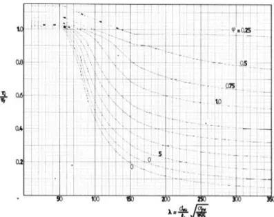
Figure 4.11 - Ultimate compressive stress 𝜎𝑐 ... 57
Figure 5.1 – West Elevation of Ashworth Road Viaduct ... 61
Figure 5.2 – Location of Ashworth Road Viaduct ... 62
Figure 5.3 - Steel Box Girders and Reinforced Concrete Slab ... 63
Figure 5.4 - Pinned Mechanical Bearing at Trestle ... 63
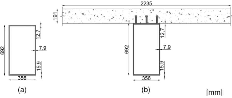
Figure 5.6 - Illustration of the different sections of the Girders (Top Plan of Ashworth Viaduct) 65 Figure 5.7 – Cross-section G1, span 1&5, steel only (a) and composite (b) (dimensions in mm66
Figure 5.8 – Schematic representation of the Trestles in perspective ... 66
Figure 5.9 - Schematic Representation of Trestle 1 (dimensions in mm) ... 67
Figure 5.10 – Schematic representation of the deck slab supported in the girders (dimensions in mm) ... 68
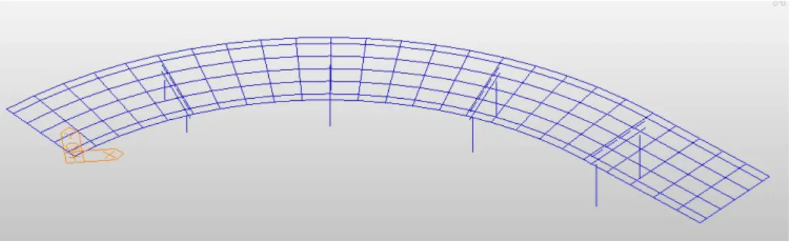
Figure 5.11 - Grillage model used for the Structural Assessment of Ashworth Viaduct ... 68
Figure 5.12 – Graphical illustration of K factors for Heavy Traffic Good Surface (Hg) ... 71
Figure 5.13 – Graphical representation of limiting shear strength 𝜏𝑙 for 𝑚𝑓𝑤 = 0,005 ... 74
Figure 6.1 – Schematic representation of the girders under consideration (G1and G3) ... 79
Figure 6.2 – Graphical illustration of 𝑀𝐸𝑑/|𝑅| results due to Self-weight along Girder 1 ... 80
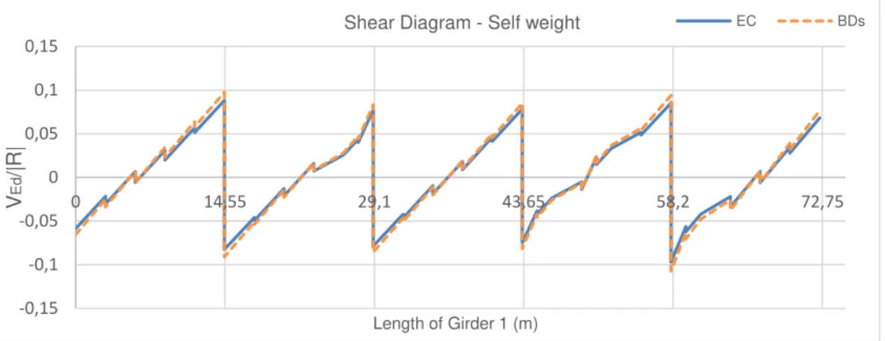
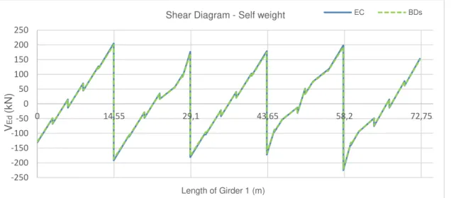
Figure 6.3 - Graphical illustration of 𝑉𝐸𝑑/|𝑅| results due to Self-weight along Girder 1 ... 80
Figure 6.4 - Graphical illustration of Bending Moment results due to Self-weight along Girder 1 ... 81
Figure 6.5 - Graphical illustration of Shear Force results due to Self-weight along Girder 1 ... 81
Figure 6.6 - Graphical illustration of 𝑀𝐸𝑑/|𝑅| results due to combinations 1a and 2a along Girder 1 ... 82
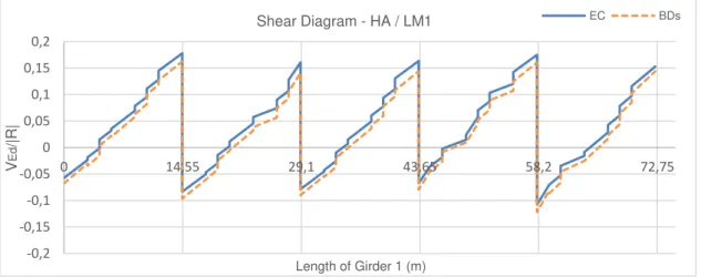
Figure 6.7 - Graphical illustration o𝑉𝐸𝑑/|𝑅| f results due to combinations 1a and 2a along Girder 1 ... 82
Figure 6.8 - Graphical illustration of bending moment results due to Combinations 1a and 2a along Girder 1 ... 83
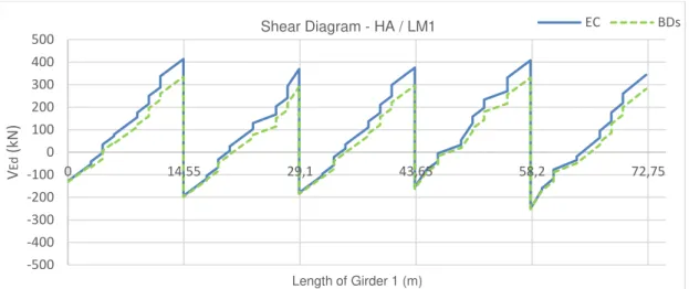
Figure 6.9 - Graphical illustration of shear force results due to Combinations 1a and 2a along Girder 1 ... 84
Figure 6.10 – Position of SV 80 producing the maximum bending effects ... 84
Figure 6.11 - Graphical illustration of 𝑀𝐸𝑑/|𝑅| of results due to combination 1b and 2b along Girder 1 ... 85
Figure 6.12 - Graphical illustration of 𝑉𝐸𝑑/|𝑅| f results due to combination 1b and 2b along Girder 1 ... 85
Figure 6.13 - Graphical illustration of bending moment results due to Combinations 1b and 2b along Girder 1 ... 85
Figure 6.14 - Graphical illustration of shear force results due to Combinations 1b and 2b along Girder 1 ... 86
Figure 6.15 - Graphical illustration of 𝑉𝐸𝑑/|𝑅| of results due to combination 1c and 2c along Girder 1 ... 86
Figure 6.16 - Graphical illustration of 𝑀𝐸𝑑/|𝑅| of results due to combinations 1c and 2c along Girder 1 ... 87
Figure 6.17 - Graphical illustration of bending moment results due to pedestrian load along Girder 1 ... 87
Figure E.10 - Graphical illustration of 𝑉𝐸𝑑/|𝑅| results due to combinations 1a and 2a along
Girder 1 ... 124
Figure E.11 - Graphical illustration of 𝑀𝐸𝑑/|𝑅| results due to combinations 1e and 2e along Girder 1 ... 124
Figure E.12 - Graphical illustration of 𝑉𝐸𝑑/|𝑅| results due to combinations 1e and 2e along Girder 1 ... 124
Figure AA.1 – SV 100 load model ... 125
Figure AA.2 – SV 150 load model ... 125
Figure AA.3 – SV-Train Load Model ... 125
Figure AA.4 – SV TT Load Model ... 126
xi
List of Tables
Table 3.1 – The 10 categories within the Eurocodes standards ... 22
Table 3.2 – Some codes of practise included in DMRB standards ... 27
Table 4.1 – Yield stress to be considered in an assessment ... 33
Table 4.2 - Specified documents to find some properties of materials ... 34
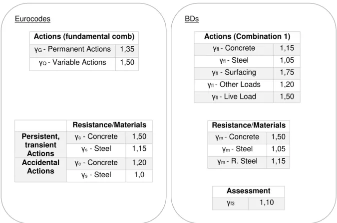
Table 4.3 - Description, symbol and localization of the partial factors in both standards ... 36
Table 4.4 - Partial Factors used in the case study for fundamental combination and combination 1, respectively... 36
Table 4.5 – Number and width of Notional lanes, according to the Eurocodes ... 39
Table 4.6 - Number of Notional Lanes, according to BDs ... 39
Table 4.7 – Values of Loads used in Load Model 1 ... 41
Table 4.8 – Assessment Live loading for accidental actions, according to BDs ... 47
Table 4.9 - Summary of actions and respective clauses in both standards ... 48
Table 4.10 – Classification of steel cross-sections ... 50
Table 4.11 - Allowable longitudinal and transverse space of shear connectors ... 51
Table 4.12 - Moment of Resistance defined by each standard ... 52
Table 4.13 - Equations used to verify the capacity of a girder under pure shear ... 54
Table 4.14 – Equations related to Compression Resistance ... 56
Table 5.1 – Dimensions of the cross-sections of Trestles ... 67
Table 5.2 – Division of lanes, according to Eurocodes and BDs ... 69
Table 5.3 – values of Braking Load for both Standards ... 70
Table 5.4 – Moving loads applied in the models related with each standard ... 70
Table 5.5 – Adjustment factors for Load model 1 ... 71
Table 5.6 – Recommended values of 𝜓 factors for road bridges ... 72
Table 5.7 – Actions applied according to LM1 ... 72
Table 5.8 – Modular ratio, width and effective width of the composite flange (girder 1) ... 73
Table 5.9 - Classification of Girder 1 on spans 1&5 ... 73
Table 5.10 – Bending Resistance of G1, spans 1&5, obtained in both Standards ... 74
Table 5.11 - Classification of Girder 1 on trestles 1&4 ... 75
Table 5.12 – Bending Resistance of G1, Trestles 1&4 ... 75
Table 5.13 – Shear Resistance of G1, Trestles 1&4 ... 76
Table 5.14 – Resistance against Torsion ... 76
Table 5.15 – Classification of the sections of the trestle ... 77
Table 5.16 -Bending Resistance of section AA ... 77
Table 5.17 - Bending Resistance of section BB ... 77
Table 5.18 - Bending Resistance of section DD ... 77
Table 5.19 - Shear Resistance of section AA ... 78
Table 5.20 – Axial Compression Resistance of section BB ... 78
Table 5.22 – Bending capacity of the concrete slab ... 78
Table 5.23 -Shear resistance of the concrete slab... 78
Table 6.1 – Comparison between LM1 and HA ... 83
Table 6.2 – Comparison of the relative results of 𝑀𝐸𝑑/|𝑅| between the standards ... 93
Table B.1 - Section Characteristics of girders from span 1&5 (midsection) ... 103
Table.B.2 - Section Characteristics of girders from span 2,3&4 (midsection) ... 103
Table B.3 - Section Characteristics of girders from trestles 1&4 ... 103
Table B.4 - Section Characteristics of girders from trestles 2&3 ... 103
Table B.5 – General dimensions of the Trimmer ... 104
Table B.6 – Dimensions and details of the concrete slab ... 104
Table B.7 - Lengths of the spans ... 104
Table B.8 – Carriageway Details ... 104
Table B.9 - Dimensions of the Trestles in mm ... 105
Table B.10 – Unit Weight of the materials (kg/m3) ... 105
Table B.11 - Steel properties according to BDs (left) and the Eurocodes (right) ... 105
Table B.12 - Concrete Properties according to BDs (left) and the Eurocodes (right) ... 105
Table C.1 – Section properties of girders from spans 1&5 (midsection)... 107
Table C.2 - Section properties of girders from spans 2,3&4 (midsection) ... 107
Table C.3 - Section properties of girders from trestles 1&4 ... 107
Table C.4 - Section properties of girders from trestles 2&3 ... 107
Table C.5 – Transformed section properties of girders from spans 1&5 (midsection) ... 108
Table C.6 – Transformed section properties of girders from spans 2,3&4 (midsection) ... 108
Table C.7 - Combined section properties of girders from trestles 1&4 ... 108
Table C.8 – Combined section properties of girders from trestles 2&3 ... 108
Table C.9 –Properties of cross-section AA ... 109
Table C.10 - Properties of cross-sections BB and DD ... 109
Table D.1 – Results for the capacity of girders against bending and shear (Spans 1&5) ... 120
Table D.2 - Results for the capacity of girders against bending and shear (Spans 2,3&4) ... 120
Table D.3 - Results for the capacity of girders against bending and shear (at Trestles 1&4) .. 120
xiii
List of Abbreviations, Acronyms and Symbols
Abbreviations and Acronyms
AF Adjustment Factors
AIP Approval In Principle
AW Authorized Weight
BAs Advice Notes
BDs Bridge Departmental
BS British Standards
BSI British Standard Institution
CEN European Committee for Standardisation
DMRB Design Manual for Roads and Bridges
DOT Department of Transport
DSIR Department of Scientific and Industrial Research
EC Eurocodes
EN European Standards
ENVs Provisional European Standards
KEL Knife Edge Load
LCC London Country Council
MOT Ministry of Transport
NA National Annex
NAD National Application Document
SLS Serviceability Limit State
SO Special Order vehicles
STGO Special Types General Order vehicles
UDL Uniformly Distributed Load
Symbols
Eurocodes
𝐴𝑑 Design value of an Accidental Action 𝐴𝑠 Area of tension reinforcement 𝐴𝑣 shear area
𝐵, 𝑏 Width of the section 𝐷 Depth of cross-section
𝑑 Effective depth to tension reinforcement 𝐸𝑑 Design value of effects of Actions 𝐸𝑐 Modulus of Elasticity (concrete) 𝐸𝑠 Modulus of Elasticity (steel) 𝐹𝑢 Tensile strength of the stud 𝑓𝑐𝑘 Characteristic cylinder strength
𝑓𝑐𝑑 Design value of concrete compressive strength 𝑓𝑐𝑢 Characteristic cube strength
𝑓𝑦 Yield Strength 𝑓𝑢 Ultimate Strength
𝐺𝑘,𝑗 Characteristic value of of permanent action j 𝐼𝑥𝑥 Second moment of area x-x
𝐼𝑦𝑦 Second moment of area y-y 𝐽, 𝐼𝑡 Torsional constant
𝑀𝑐𝑟 Elastic cristical moment for lateral-torsional buckling 𝑀𝐸𝑑 Design Bending Moment
𝑀𝑐,𝑅𝑑 Design Resistance for Bending 𝑀𝑏,𝑅𝑑 Design buckling Resistance Moment 𝑁𝐸𝑑 Design normal force
𝑁𝑐,𝑅𝑑 Design resistance to normal forces
xv 𝑃 Representative value of prestressing action
𝑃𝑓 Probability of failure
𝑄𝑓𝑤𝑘 Characteristic value of Concentrated Load
𝑄𝑖𝑘 Magnitude of characteristic axle loads on notional lane number i
𝑄𝑘,𝑖 Characteristic value of the accompanying action on notional lane number i 𝑄𝑘,𝑙 Characteristic value of the leading variable 𝑙
𝑄𝑙𝑘 Magnitude of the characteristic longitudinal forces
𝑞𝑖𝑘 Magnitude of the characteristic vertical distributed load on notional lane number i
𝐿 Loaded length
𝑅𝑑 Design value of the Resistance
𝑇𝐸𝑑 Design value of total torsional moments 𝑇𝑅𝑑 Design resistance to torsional moments 𝑡𝑤 Thickness of the web
𝑡𝑤𝑒𝑙𝑑 Thickness of the weld 𝑡𝑓 Thickness of the flange 𝑉𝐸𝑑 Design vertical load
𝑉𝑝𝑙,𝑇𝑅𝑑 Reduced design plastic shear esistance 𝑉𝑅𝑑 Design shear resistance
𝑉𝐿,𝐸𝑑 Longitudinal Force 𝑊𝑦 Section modulus 𝑊𝑒𝑙 Elastic section modulus 𝑊𝑝𝑙 Plastic section modulus 𝑌𝑝 Plastic neutral axis
𝑌𝑒 Distance to combine centroide 𝑤𝑙 Width of lane
𝑧 lever arm
𝛼𝑄𝑖, 𝛼𝑞𝑖 Adjustment factors of some load models on lanes i
𝛾𝑀0 Partial factor Resistance of cross-section whatever the class is
𝛾𝑚 Partial safety factor for a material property 𝛾𝐺 Partial safety factor for Permanent Actions 𝛾𝑟𝑒𝑠 Partial safety factor for Resistance
𝜂, 𝜉 Factors defined in text 𝜆𝐿𝑇
̅̅̅̅ Non-Dimensional slenderness for lateral-torsional buckling
𝜌 Reduction factor 𝜎 Standard Deviation
𝜏𝐸𝑑 Design value of the load shear stress
𝜏𝑡,𝐸𝑑 Design shear stresses due to St. Venant torsion 𝜒𝐿𝑇 reduction factor for lateral-torsional buckling 𝛽 Reliability Index
𝜓0 Factor for combination value of a variable action 𝜓1 Factor for a frequent value of a variable action
𝜓2 Factor for a quasi-permanent value of a variable action
UK standards for structural Assessment (BDs) 𝐴𝑒 Effective Area
𝐴𝑓𝑒 Area of the effective flange section
𝑑𝑓 Distance between the centroids of the two flanges 𝑑𝑤 Overall depth of a rolled section
𝐹𝑓 Limiting force in the flange
ℎℎ Height of the largest hole or cut-out 𝑄𝐴∗ Assessment Loads
𝑄𝑘∗ Nominal Loads
𝑟𝑦 Radius of gyration around y axis 𝑟𝑧 Radius of gyration around z axis
𝐿 Loaded length
𝑙𝑒 Effective length 𝑀𝐷 Bending Resistance
xvii
𝑚 Ratio
𝑃𝑚𝑎𝑥 Maximum axial load 𝑟𝑥𝑥 Radius of gyration x-x 𝑟𝑦𝑦 Radius of gyration y-y 𝑆𝐴∗ Load effects
𝑧𝑒𝑙 Elastic section modulus
𝑍𝑥𝑐 Elastic section modulus x-x compression 𝑍𝑥𝑡 Elastic section modulus x-x tension 𝑧𝑝𝑒 Plastic section modulus
𝛾𝑓𝑙 Partial factor for actions
1
Chapter 1
1. Introduction
1.1 Preliminary Remarks
Since ancient times, there has always been a need of communication between nations, whether it was for commercial, military and spiritual reasons or for simply spreading the evolution of technology and knowledge, between cities, ports or any kind of separate land.
By levelling up uneven terrain and span mountains, rivers, lakes or even oceans, Roman civilization began to revolutionize the meaning of bridges with the introduction of arch bridges in the world, being United Kingdom, no exception. The concept of bridge was quite unknown until the first types of bridges started to show up in an arch form either from wood, stone or brickwork [1].
Despite of their medieval existence, the majority of arch bridges in UK were constructed from the 18th and 19th century, as first the canal, then the railway and suddenly the road networks were subject to rapid expansion. The Roman Empire was the undoubtedly pioneer in this type of bridges by showing the great impact that this period had on history [2].
Nowadays, stone bridges are no longer being built and they are only a national heritage in various countries of the world noticing, though, that many of them are still standing and most are in service. In the early medieval England, known by Anglo-Saxon times, there was an increase of concern on these bridges preservation and maintenance, not only because of the noticeable increasing of traffic load overtime, as also the fact that they are vulnerable to natural hazards, human actions and aggressive environmental conditions. Therefore, methods of analysis have been made just to repair, restore or rebuild these types of bridges in order to avoid disturbance of the network [3].
climate changes. Knowing that it can affect even the structural part of the bridge there are some strategies concerning this issue to guarantee the safety of their use.
Therefore, maintenance, repair and rehabilitation have been looking for an equilibrium between the first conception of the bridges and their new requirements and trying to adapt them to the new regulations in force, always respecting the preservation and integrity of the structure. However, as it is expected, ancient bridges in general, will never have more durability than the new ones [4].
It is also important to make a clear distinction between the meaning of roadway and railway whereby the first one consists on a pavement with a specified width usually with shoulders on each side whilst regarding the railways, the routes consist in a pair of steel rails which are laid parallel to each other. The traffic destined for roadways are all type of cars, truck, buses, cycles, pedestrians etc. whilst the railways are only made for the movement of trains.
However, a few bridges of this type were constructed after the first world war not only because most part of them had been destroyed and needed repair but also because like any other kind of construction or technology, always go through evolution and development. Thus, construction of bridges, their materials and performance rapidly became better understood as time went by. Therefore, it is possible to divide the history of bridges in many different parts, more or less independent from each other, being the increase in demand for concrete, iron and steel as construction materials the most important part of that.
As many other characteristics, large spans are a fundamental part in the history of bridges because they are the most representative element of progress and development. It was first started with a simple trunk of wood, going through a junction of several trunks laid side by side forming thus a simply supported beam, going bigger as time went by and being replaced by portal frames and arches truss beams [3].
1.2 Scope
It is a reality that road traffic has been increasing over time, not only in volume but also in gross weight, which has brought, as expected, a constant need of concern of assessing the condition and strength capacity of bridges as time goes by. It can be justified by the fact that these new loads may not be compatible with the design of the existing bridges under consideration, which could have been constructed in a totally different period when the requirements for load traffic and materials strength were completely different.
3 This comparison will be based in the main requirements of both standards when regards to actions applied on general road bridges and also in the resistances of steel, concrete and steel-concrete composite structures. It is intended to analyse the results obtained in the structural members of both models, to understand their differences and similarities and take valid conclusions that can possibly help in a positive upgrade of both standards regarding the assessment of existing bridges.
1.3 Organization of the Dissertation
This dissertation is divided in 7 chapters described below:
Chapter 1 – Introduction: This Chapter presents an introduction of the underlying subject, highlighting the importance of the assessment and maintenance of bridges nowadays, which leads to the main scope of this work;
Chapter 2 –Evolution of steel, concrete and composite bridges in the UK: it Is made a historical context regarding the evolution of steel, concrete and composite bridges in the UK, connecting the materials used according to the period under consideration. Furthermore, it is made an approach of the composition and evolution of those materials;
Chapter 3 – Introduction of the Eurocodes and UK standards (BDs): In this Chapter, an introduction is made regarding the standards that are going to be compared throughout this work. A brief historical contextualization is carried out both in Eurocodes and BDs standards, followed by its respective organization, aims and contents. When comes to BDs standards, it is made an approach regarding the different kind of inspections considered in the UK for bridges maintenance;
Chapter 4 –Main Differences between the Eurocodes and UK standards (BDs): This chapter is carried out towards a detailed comparison between the two codes enumerating the different requirements regarding materials properties, actions, combinations of actions and materials resistance related to structural forces;
Chapter 5 – Case Study of Structural Assessment- Ashworth Road Viaduct: This Chapter is entirely dedicated to the case study of Aswhorth Road Viaduct, where is made a brief introduction of the case such as its location, historical information and description. Afterwards, the model of the case is introduced having as basis the principles mentioned in chapter 4 when regards to the actions applied in both standards as well as the results of the structural members capacity;
5
Chapter 2
2. Evolution of Steel, Concrete and Composite Bridges in the UK
2.1 Structural Materials
2.1.1 Concrete
The use of concrete as a construction material, in a gross way of its meaning, has started long time ago in the Middle East when, unintentionally, the builders mixed pounded-clay and thin damp limestone, which, reacting with gases from the air formed a strong protective surface that is nowadays called cement. Overtime, the need of building strong structures and demanding a greater durability, forced the Romans to improve this type of cement, discovering then the pozzuolana1. They used this material in marine structures and in those that were exposed to water
such as docks, aqueducts and bridges. However, the material that exists today was still unknown until 1824, when Joseph Aspdin, an English entrepreneur and manufacturer in the United Kingdom, created equivalent to Portland cement. The name Portland arose after the high-quality building stones discovered in Portland, England. Although it was not that common for aesthetic reasons, in the early 19th century, concrete started to be used in industrial buildings and private
houses, generally as a non-reinforcement mass concrete. [5]
Concrete is a material formed by the admixture of a hydraulic binder (cement), large and fine aggregates and water. It can also contain additions and adjuvants to improve its characteristics. The kind of cement has an important role in the reactivity and the water amount being used in the process, affecting also the concrete strength. The aggregate can be chosen specifically to produce concrete in order to develop certain properties, for instance using materials like clay and expanded shale for light concrete. This constituent is a large portion of the concrete material, varying from 70 to 80% of the total volume of concrete [5].
Regarding the process that concrete goes through, it is possible to distinguish two different phases such as the fresh concrete state and the hardened concrete state. In the first one, the
1 a mixing of siliceous and aluminous materials in a finely divided form which in the presence of water, reacts
material is still malleable, and it can be compacted while it does not obtain its resistance. Then it starts to harden, gaining thus some resistance and stiffness reaching its high potential at more or less 28 days. Therefore, concrete can be classified into three types according to its density. They are known by normal concrete with a density varying between 2000kg/m3 and 2600kg/m3, heavy
concrete when its density is above 2600kg/m3 and light weight concrete which has a density not
greater than 2000kg/m3 [6].
After concrete has reached its full capacity, there is a significant subject that must be taken into account, it is the characterization of the fracture surface. It is known that concrete has little resistance under tensile stresses, so although reinforced concrete subjected to flexure has been designed to crack, it is controlled by the distribution of steel reinforcement. Thus, the cracking of concrete, mainly based on concrete composition, plays an essential part in the evaluation of fractures mechanics properties of cementitious materials. This characterization also depends on the load applied during the test, being afterwards an important process for the mechanical behaviour of this material. As far as it is known, water binder ratio, maximum aggregate size and aggregate type can have a great influence on the fractal dimension verified in the concrete when subjected to a certain load. Some tests have been carried out to see how much the fractal dimension varies with the amount of these constituents and the conclusions are clear that the cracks increase almost linearly with the water binder ratio, so as the size of the aggregate.
In the end, the combination of the three constituents of concrete in addition to these characteristics mentioned above have to satisfy the minimum performance specifications such as shrinkage, creep, modulus of elasticity, compressive strength, durability and workability, required for structural concrete [5].
2.1.2 Steel
The origin of the production of steel is still a bit unknown. However, it is thought to have started with some investigations using bloomery hearth furnaces and taking into account some aspects such as the quality and preparation of the ore being processed, the material and the shape of furnace walls. With these experiences, it was defined different designations for iron and steel depending on the way they were produced and processed, being thus steel characterized by having a higher tensile strength and greater hardness due to the higher quantity of carbon. [7]
Cast iron was known by its brittleness and low shock resistance whereby plenty of variations were made to improve the qualities of this material, despite not having succeeded. However, it was noticed that this material showed a compressive strength 100 times greater than the one observed in stone, it was not long before the building industry became interested in the new material and so they started their first tentative in industrial buildings and bridges [7].
7 Finally, steel is the last material showing up, being its properties and performance consequence of the combination of its chemical composition and process of production, including its heat treatment [8].
The use of these materials can be divided into three periods in history, cast iron (1780-1850), wrought iron (1850-1900) that replaced cast iron and at least steel, used since 1880 until the present which enabled the construction of bridges to become larger and lighter. The material is a fundamental part regarding bridge design, not only because resistant properties of the bridge heavily depend on the dimensions of the material, but also because of their technological properties such as manufacturing capacity, joints or shapes of basic elements. Metal has always been ahead of concrete when it comes to dimensions of bridges, which means it has a greater capacity to span big bridges due to its higher specific strength. There are three different types of metal, showing different characteristics among them, that have been through evolution, not only in the composition but also in the way of manufacturing them, which enables to distinguish them as wrought iron, cast iron and steel [7].
2.1.2.1 Cast Iron
Cast iron is an iron-carbon metal, known by containing more than 2% of carbon which is considerated a high level of carbon. Cast iron can be divided in three most common types: white, gray and nodular cast iron. With the gray one being the most used due to its lower costs, although it has a good behaviour when subjected to compression, the opposite occurs when it is subjected to tension. Thus, this material is often used in parts of the bridge that are subjected to compression, such as arches, columns etc. Overall, cast iron combines many features such as vibration damping and long lifecycle as a result of various conditions and graphite formations. However, it has some negative aspects which are: being a brittle material and having a poor resistance to impact and shock. Hence, cast iron is not suitable for welding since it can lead to brittle cracks in and around welded joints [9].
2.1.2.2 Wrought iron
Wrought iron was the first metal classed as structural steel. However, its characteristics are noun-homogeneous and especially bad in the thickness direction due to the manufacturing process. Contrary to the cast iron, it has a low content of carbon, an average of 0.08% but a high quantity of phosphor and nitrogen which reduces the ductility capacity and accelerates the process of ageing. The metal was used in structures until it was replaced by steel at the end of 19th century [7].
2.1.2.3 Steel
safety, since it gives a previous warning when there is a structural failure, with a reaction produced when the plastic state of the material is achieved. Although the fact that steel is a good material in multiple aspects, there are some factors that must be considered about bridge design and maintenance, such as fatigue, corrosion and connections between structural parts, known to weaken and influence the time of steel [7].
2.2 The Evolution of Steel Bridges in the UK
The use of iron as a construction material on bridges was recorded around 1780, being substituted by steel in 1880. This one became a permanent position in modern construction due to its special properties.
It is thought that the main history of metal bridges in the UK began in 1779 with the greatest construction of a cast iron arch bridge in the world, called Iron Bridge with a 30m span built by Abraham Darby III. This bridge was considered the dawn of the Industrial Revolution. The bridge is located in Coalbrookdale, England, crossing the River Severn, exemplified in Figure 2.1. Cast iron began to be used in the construction of bridges and it was an authentic revolution in bridges [10].
Twenty years later, it was finally constructed the bridge that is still considered the largest cast iron arch bridge with a span of 73m, the Southwark bridge crossing river Thames, also situated in UK and illustrated in Figure 2.2 [10].
9
Figure 2.2 - Southwark bridge [11]
Many pointed arch bridges were built during the Middle Age, however it did not make a difference in its structural type, only in the shape of the arch that was considered of being less suited than the semi-circular arches for load actions. In the mid 19th century, engineers first used this material
as a reinforcement because of its advantage to accommodate tensile forces.
In the early nineteenth century, suspension bridges, a type of cable-supported bridges, came also to replace the arch bridges since they could span larger decks, being ideal for covering big waterways. The cables for this kind of bridges are suspended vertically from the main cable, anchored at both ends of the bridge and running between the towers. The first to appear and rapidly spread all over the world were catenary bridges, the classical catenary bridges where the cables are separated from the deck and every part of it are in perfect equilibrium [3].
This kind of bridges are then used not just because they can span larger decks but also due to their lightweight, aesthetic appearance, high strength and capacity and finally ease of construction. However, they have a high sensitivity to dynamic loads, since the long decks and the cables create a flexibility that allow the bridge to be more sensitive to that kind of effects [12].
The first bridges constructed with wrought iron were two large box girder railway bridges named Canway and Britannia bridges over the Menai Strait, built by Robert Stephenson around 1850. These two constructions were quite popular back then, not only because they were the first made of wrought iron but they were also the first box girder being constructed. Later, in the end of 19th
century, there was a spectacular development of this material, beginning the era of steel known by the “metal bridge boom” depending largely in the need of making a great number of bridges and viaducts for railway lines purpose, some of them requiring a considerable size [3].
By the 19th century, not much time after suspension bridges appeared, trussed girder bridges
started to be developed, with a combination between cast iron for compression and tension members respectively. This type of bridges was especially used in the railway construction due to the need of carrying heavy loads and maintenance facilities. Shortly, bridges’ construction evolution saw a huge development related to trussed girders. The first iron truss railroad bridge, with a peculiar construction of lattice trusses, was constructed by George Stephenson in 1824 and it was called Gaunless Viaduct. This bridge used to be located in West Auckland crossing the river Gaunless, ending demolished a little over one hundred years after its opening. It can be seen an example of the ancient bridge in Figure 2.4 [13].
11 Cable-stayed bridges, another type of cable-supported bridges, were recorded to be the last ones to appear in the mid twentieth century and they had a really fast development in history, both in steel and concrete. They have basically the same concept as the suspension bridges such as the presence of cables, towers and girders. However, in this case, the cables are directly attached to the deck, supporting this one and normally forming a series of parallel lines. Similar to suspension bridges, cable-stayed bridges have also a high sensitivity to dynamic behaviours and almost an equal capacity for spanning large decks, reaching lengths’ up to 800m. Due to the first parameter and in addition to some probably lack of technical and analytical understanding, cable-supported bridges led to a few historic bridges’ collapse. There are a lot of causes that can lead to a bridge collapse such as natural causes, accidental impacts, structural and design mistakes, construction deficiencies or even the lack of maintenance and inspection of bridges which represents only 5% of the collapses. A great example of bridge disasters happened in the UK due to miscalculation of dynamic forces is the Tay bridge disaster, designed by the railway engineer Thomas Bouch, occurred in 1879, Scotland (Figure 2.5) [3].
Tay rail Bridge was the first railway bridge being constructed in Scotland and it was classified as the longer bridge in the world, back in 1877. The bridge consisted of steel lattice girders, combining cast and wrought iron, high pillars of cast iron tube as supports and a total deck length of 3264m. In the year of 1879, a disaster derived of a storm happened while a train was passing by, ending up destroying the whole central part of the bridge along with the train. Due to the load combination of the storm and the train, a pillar ended up buckling and took the continuous bridge girder with it. It is thought that the causes behind this epic disaster are derived from the insufficient assumption of wind forces, poor workmanship and low-quality material, becoming this bridge an issue of investigation, even nowadays [3].
Today there is another bridge replacing the old Tay bridge (Figure 2.6). It was constructed between 1882 and 1887 and spans a length of 2250 m in total. [3] This bridge was the first greater box girder bridge in Britain. The superstructure was made of a series of simply supported spans of 55m each, with two decks made of a single closed box section. For the areas of sagging moment only, it was considered composite sections whilst in the hogging moment regions have as a resistant section, the steel box section only [14].
2.3 The Evolution of Concrete Bridges in the UK
Early concrete bridges started to appear in an arch form, like masonry bridges, using just the compressive strength of concrete since this material has low resistance in tension. The history of concrete in the United Kingdom started in Inverness and Edinburgh, Scotland with the beginning of construction of concrete roads in 1865 when it was built the first plain concrete bridge designed by Thomas Marr Johnson, tooking place in West London. Overtime, plain concrete started to be used more and more for the construction of bridges by British engineers, having as an example of this, a three-span concrete arch, including a 15.2 m middle span, built by Philip Brannan in Devon, in 1877. Railway engineers were remarkable as well in single plain concrete in examples such as the Dochart Viaduct (Figure 2.7) built in 1886, Killin, Scotland [15] and the Cannington Viaduct in 1903. This last one shows a 186 m length with ten elliptical arches 15 m long and 28
Figure 2.5 - Tay Rail Bridge [3]
13 m high, connecting the seaside town of Lyme Regis with the main line railway network at Axminster, southwest England, as it can be seen in Figure 2.8 [16].
In Great Britain, an example of an early mass concrete bridge is the spectacular Glenfinnan Railway viaduct in Scotland, constructed in 1897 by Robert McAlpine and opened in 1901. This viaduct has a length of 380m, 21 arches and shows a 15 m length for the biggest span. Crossing the river Finnan, this viaduct connects Glasgow with Maillag through the West Highland line which is situated 30 m above the ground and shows a curve geometry as it can be seen in Figure 2.9 [16].
Figure 2.7 - Dochart Viaduct [50]
In 1867, without any knowledge or any method for design calculations, Joseph Monier invented reinforced concrete, based on the idea of putting steel and concrete together and bringing the best quality of each material into performance. The first bridge constructed using reinforced concrete was probably Homersfield Bridge over the river Waveney on the Norfolk/Suffolk border in 1870 (Figure 2.10). It has 15 metres span and it is made of wrought iron embedded in concrete. About the first reinforced concrete railway bridge, Mouchel (Bristol, 1907) and Coignet (Bargoed, Wales) worked together contributing with the design of an 8.5 m span structure built in Dundee, Scotland, in 1903 [15].
This technique of using reinforced concrete was perfected by Francoise Hennibique, and its application to bridges was carried out by Robert Maillart during the first part of the 20th century
[16]. Hence, by the 1930s, there was a significant increase in the use of reinforced concrete and so it began to have a very important role in society due to its strength, design flexibility and natural durability, becoming thus, the major construction material [17]. Around this time, there were about 2000 reinforced concrete bridges in the UK and it was still being used in the 1950s for larger
Figure 2.9 - Glefinnan Viaduct [51]
15 bridges, especially arches. However, by the end of the 1960s it had been mostly superseded by prestressed concrete [18].
After reinforced concrete had been developed, it was noticed that the performance of the bars was improved when they were placed in tension, leaving the concrete in compression. During some experiences, although the trend to crack in tension was notoriously reduced, the cracks started to reappear after some months, it was then realised that creep occurred. So, it began the era of prestressed concrete invented by Eugene Freyssinet around 1929 [16]. In the UK, the use of prestressed concrete in bridges started in London around 1947 when it was used precast prestressed in the girders for the reconstruction of two bridges carrying roads over railways. Thus, it led to a major construction such as Nunn’s bridge (Figure 2.11) in Boston, 1948, which is thought to be the first in-situ prestressed post-tensioned concrete bridge, with a span of 22,5m, result of a partnership between prestressed Concrete Company and Mouchel Consulting [19].
Later on, prestressed concrete rapidly superseded reinforced concrete, gaining a more important role in the late 1960s with the arising of huge constructions such as Hammersmith Flyover (Figure 2.12), the first modern elevated urban motorway constructed in 1961 that became a landmark structure in the UK. The increasing need of construction of motorways due to the vast growth of load traffic led to a large number of concrete bridges, not specifically because of the style, but due to economy and durability issues that became more important overtime [18].
Figure 2.11 - Nunn's Bridge [19]
As well as the innovation of prestressed concrete, precast concrete showed up just in the right time also showing a constant growth in its techniques such as the number of prefabricated bridges, its size and weight, helping thus the economy section by being a faster solution. [19]
2.4 The evolution of steel-concrete composite bridges in the UK
The beginning of construction of composite bridges came with the development of concrete structures in the 1800s when it was experimented the embedment of iron into the concrete, producing the first iron–concrete composite structures. An example of this type of structure is Brunel’s bridge near Paddington [20].
United Kingdom has been recognized by their tradition in the construction of steel bridges, being one of the first countries introducing the construction of composite bridges. During the 1950s and 1960s a big evolution of the railways and motorways has been registered, helping in the growth of this type of bridges. Therefore, Pelham bridge (Figure 2.13) constructed in 1958 and located in Lincoln, UK, was one of the earliest bridges introduced in this type of construction. It is constituted by four plate girders site welded with steel-rubber laminated bearings. The design for shear connectors has been based in tests carried out by the University of Illinois, USA, since at the time it did not exist standards for composite bridges [21].
In the 1960s, the industry of steel in the UK was known by their high yield steel quality and their fast improvement in welding techniques, which led to an increase of competitiveness regarding steel and composite constructions. It has also been noticed that composite constructions started with medium spans being rapidly extended for large spans which was only verified in prestressed concrete box girders until then.
The first publication related to composite bridges showed up in 1967 with the publication of CP117 – Composite Construction in Structural Steel and Concrete, Part 2: Beams for Bridges. In 1969 was constructed one of the first modern composite bridges that presented a complete continuousness of the girders over the columns, called M74 Raith bridge (Figure 2.14) spanning Clyde river. Raith bridge is composed by a pair of trapezoidal open top box sections with transverse steel cross girders supporting a reinforced concrete slab [14].
17 In 1973, a new approach for composite bridges has been brought by G. Maunsell and Partners in South Wales. The bridge was named Saltings viaduct and consisted in a continuous structure with spans of 31 m and a plan radius of 1000 m, having as structural elements four steel box girders with a reinforced concrete deck slab, as can be seen in Figure 2.15 [14].
After the new regulations established in the UK with the publication of BS 5400: steel, concrete and composite bridges, in 1979, Friarton Bridge (Figure 2.16) arose as a typical bridge designed under those standards. The bridge is also a steel box girder bridge, displaying a tapered section, with a concrete slab, across the River Tay in the outskirts of Scotland, Perth [14].
Figure 2.15 – Saltings Viaduct [14]
Figure 2.16 – Friarton bridge [59]
It is recognised nowadays, that composite bridges represent 8% of the total existing bridges in the UK, which is already a significant number, knowing that this type of construction is the most recent one [14]. This fast growth of the composite bridge industry can be justified by the several advantages existent in this type of construction such as the high tensile and shear strength united with the low cost of the compressive strength of the concrete, the rapidly construction and having a less critical demolition than prestressed concrete box girders (significant for medium span bridges). However, composite bridges are more suitable for simply supported beams since, when considering continuous beams, although they can take full advantage of the sections resisting to sagging moments, the same does not apply for the negative bending regions. It can be justified by the fact that concrete is exposed to tension and steel is exposed to compression [22].
Within composite bridges construction, there are several types of bridges that can be adopted by the British design, being the more common described below:
❖ Multi girder systems
❖ Twin I-girders
❖ Multiple box girders
❖ Open top trapezoidal box sections
The first composite bridges to appear was the multi-girder bridges (Figure 2.17) being distinguished by having multiple I-girders or trusses supporting the concrete slab. The main idea was to secure a substitute load path in the case of a girder fail. Besides that, the spacing of the multiple I-girders is usually small which allows the use of thinner (200-250 mm) precast deck panels [14].
Overtime, this kind of construction has been abandoned and replaced by other types of composite bridges, already mentioned above. Twin I-girders (Figure 2.18) started to develop with the advances in welding techniques of thick plates. These bridges can span from 50 m to the much longer span of cable-stayed bridges (approximately 800 m) and besides the fact of needing less material than the multi girders system, they also need less web stiffeners, cross-frames and lateral bracing [22].
19 However, if it is intended a better stability of the system, it can be obtained by the invert U-frame action using cross-girders that provide restraint to the lateral torsional buckling of the main girders.
The multiple box sections (Figure 2.19) are usually appropriate for medium spans with curved alignments, due to the higher torsional effects introduced by it, on the girders. Despite of the initial high costs, it can bring some advantages, such as the box stability, span long sections can be erected without bracings and the span lengths are more economic than for concrete constructions. This type of composite bridges is very common in the UK [23].
At last, open top trapezoidal box sections with inclined webs (Figure 2.20) are also frequently used in the UK since the 1990s. This solution is even more indicated for significant curvature plans requiring a high torsional stiffness. Despite of the similar characteristics with box girders, this type of construction shows other advantages such as the inclined webs design since it allows the reduction of the width of the bottom flange, the thickness of the concrete slab and finally the need for less number of longitudinal girders [23].
Figure 2.18 -Twin I-girders without cross-girders [49]
21
Chapter 3
3. Introduction of the Eurocodes and UK standards (BDs)
3.1 Eurocodes Standards
3.1.1 Brief History of the Eurocodes
The need for the use of standard rules in construction’s field was first discussed in 21 July 1908 by the Concrete Institute, in the Ritz Hotel, London. Their work was recognized in the London County Council (LCC) Regulations of 1916 which kept in collaboration with the Department of Scientific and Industrial Research (DSIR). In 1922, the Concrete Institute have grown into the Institution of Structural Engineers. Later in 2008 the Institution, that first started with just 100 people, was already counting with a body of 22 000 members, in more than 100 countries.
Although reinforced concrete had already been used some years before, the main aims were based on the design rules for the new material. Thus, the institution followed the history from a concrete design point of view, allowing other engineers to apply the new technology. Therefore, several codes and guidelines had been developed since then and have been extended beyond many National Requirements, taking the UK a full part in this process.
resulted in a cultural, legal and technical development not only for the authors of the documents but also for society who rely on them, despite of their unfamiliarity with its content.
Public safety, durability and serviceability are really important issues for society, becoming significant aspects for regulation of construction. It brought then, new rules into the Eurocodes regarding existing structures which accurately are object of concern since they have undergone a long history of evolution. However, this concept does not mean that structures became suddenly unsafe, this only draws attention to the need of understanding, for instance, the changes on the load and consequent behaviour in the structures [24].
3.1.2 Organization of the Eurocodes
Nowadays, the Eurocodes can be found in 10 significant categories, discriminated below (Table 3.1):
Table 3.1 – The 10 categories within the Eurocodes standards
EN 1990 Eurocode 0 Basis of Design EN 1991 Eurocode 1 Actions on Structures
EN 1992 Eurocode 2 Design of concrete structures EN 1993 Eurocode 3 Design of steel structures
EN 1994 Eurocode 4 Design of composite steel and concrete structures EN 1995 Eurocode 5 Design of timber structures
EN 1996 Eurocode 6 Design of masonry structures EN 1997 Eurocode 7 Geotechnical design
EN 1998 Eurocode 8 Design of structures for earthquake resistance EN 1999 Eurocode 9 Design of aluminium structures
These codes have been approved by CEN and they could co-exist with the appropriate National code under the rules of the same authority.
3.1.3 Aims of the Eurocodes
With the introduction of the Eurocodes, many aspects regarding structural design became easier to manage. Their purpose was to serve as reference documents for structural design, trying to include the project and verification of any type of construction. To accomplish that, they had to follow some basic common rules such as:
❖ The requirement for public safety and serviceability of structures, based on the principle of risk, particularly emphasizing the safety in case of fire, the mechanical resistance and stability;
23
❖ The independence of advice and updated information;
❖ References of material properties, taking an appropriate theory approach for structural use;
❖ The durability of the structure under normal maintenance conditions, regarding economic concerns;
❖ To make harmonized technical specifications for construction products and engineering services, being a support for contract and specification and at last;
❖ Improving the competitive market between European construction Industry and the industry outside the European Union [25].
In summary, these codes are mainly to simplify the process of design, providing common structural design rules based on calculation methods, current tests, non-linear and finite element analysis, used all over the European Union [24].
3.1.4 Eurocodes Format
The common standards around European Union have a common format, being distinguished from the other codes by the clauses. They are only designated either as Principles or Rules of Application. Principles are known as the fundamental bases of structural performance that must be attained. They are identified by the letter “P”, following the paragraph number.
Rules of application are appropriate methods that must be used in order to comply those principles and satisfy their requirements. If there are alternative methods replacing the rules of Application, those ones have to be according the principles and provide the same level of reliability. Regarding rules of application, there are many parameters where only indicative values are given, being thus necessary for each country to specify their own equivalent values. These values are indicated by being enclosed by a box (│____│) and are established in the National Application Document (NAD). In this document, it is also possible to find amendments to the Eurocodes if the rules either do not apply or are incomplete.
Furthermore, The Eurocodes also have an open part that is intended for National choice, known as Nationally Determined Parameters and it is disposed in the National Annexes. The National annex may only contain information on those parameters already left open for that purpose, such as country specific data. In the other hand, everything that is considered normative, with no choice, it is transformed into National standard, comprising the full text of the Eurocode. This part may be preceded by a National title page and a national foreword.
3.1.5 Materials
Since it is being made an approach regarding steel, concrete and composite bridges, the references further ahead will be only around these materials. The codes associated with the mentioned materials are EN 1992, EN1993 and EN 1994, respectively. The part 2 (EN 1992-2, EN1993-2 and EN 1994-2) of each Eurocode is particularly apply on bridges.
These materials can appear in many forms, categories and conditions, depending on the process of fabrication or even on the need for the structure’s design. Hence, they will have a wide variety of resistance that can be checked for limit states, through specific tests according to the rules.
3.1.6 Actions
The actions applied will focus on the existent actions on bridges. These include all the general actions indicated by the Eurocode 1, part 1 (EN 1991-1) and the specific actions of traffic load described in the part 2 of the Eurocode 1 (EN 1991-2).
The Eurocodes are a practical way of assisting with design and structural verification (here after designated assessment), through an organized group of codes and standards. Hence, they have methods of procedure according with the following criteria:
❖ Verification of break or excessive deformation of the structure (STR)
❖ Verification of loss of the static equilibrium of the structure or their structural elements (EQU)
❖ Verification of break or excessive deformation of the soil that support the structure (GEO)
They include calculations procedures complying limit states approach that must be checked to verify safety requirements of structures. A limit state is a threshold that defines the moment when a structure no longer complies with a specific requirement, being then limited in some functionalities. They are:
❖ Ultimate Limit State: A state associated with structural failure and may compromise the safety of the structure and people.
![Figure 4.7 - Representation of accidental load models according to the Eurocodes (a) [26] and BDs (b) [29]](https://thumb-eu.123doks.com/thumbv2/123dok_br/16622134.740223/71.892.148.743.393.666/figure-representation-accidental-load-models-according-eurocodes-bds.webp)