Universidade do Minho Escola de Engenharia
Rui Filipe Pereira de Azevedo
Systematic Method for UML Model to
Model Transformation:
Development and Verification in Alloy
Universidade do Minho Escola de Engenharia
Rui Filipe Pereira de Azevedo
Systematic Method for UML Model to
Model Transformation:
Development and Verification in Alloy
Abril de 2012
Dissertação de Mestrado
Mestrado em Engenharia Informática
Trabalho efectuado sob a orientação de
ii
Declaração
Nome: Rui Filipe Pereira de Azevedo
Endereço Electrónico: [email protected]
Telefone: 964965426
Bilhete de Identidade: 13009435
Título da Tese: Systematic Method for UML Model to Model Transformation:
Development and Verification in Alloy
Orientador: Professor Doutor Fernando Mário Junqueira Martins
Ano de conclusão: 2012
Designação do Mestrado: Mestrado em Engenharia Informática
É AUTORIZADA A REPRODUÇÃO INTEGRAL DESTA TESE APENAS PARA EFEITOS DE INVESTIGAÇÃO, MEDIANTE DECLARAÇÃO ESCRITA DO INTERESSADO, QUE A TAL SE COMPROMETE.
Universidade do Minho, 27 de Abril de 2012 Rui Filipe Pereira de Azevedo
iii
Abstract
The Unified Modeling Language (UML) is nowadays the industry standard nota-tion for modelling software systems using an object-oriented approach. The Object Management Group (OMG) manages this standardization. UML combines several modelling techniques and its models have visual representations through UML di-agrams. Despite being widely accepted, used and also recommended by software development processes like Rational Unified Process (RUP) and Agile, two major UML weaknesses are recognized by the overall software community: it is a notation with no underlying method; it is only semi-formal.
Trying to narrow this gap, this work presents a method for the systematic transformation of UML models. Furthermore, and tackling another vulnerability of UML, its informality, we also propose a verification mechanism for checking the correctness of said transformations using the Alloy formal modelling notation.
The proposed diagram transformation method follows the RUP use case orien-tation and encompasses three UML diagrams: use case, sequence, and interaction overview diagrams.
We have developed the action step and action block constructs, which will be the basis for a more precise and standardized structure for the textual specification of use cases. Using these constructs, and without loss of expressive power, a canonical form for use cases was devised which will be the source and the anchor for the other steps of the systematic transformation method. Starting from the use cases already in the canonical form, we have created a set of steps and rules that will conduct the transformation of these use cases into sequence and interaction overview diagrams in a systematic way. With Alloy, we are able to assess the diagrams’ well-formedness and verify the correction of the transformations.
iv
Resumo
A Unified Modeling Language (UML) é hoje em dia a notação standard da indús-tria para a modelação de sistemas de software usando uma abordagem orientada aos objectos. O Object Management Group (OMG) gere esta standardização. A UML combina várias técnicas de modelação e os seus modelos têm representações visuais através de diagramas. Apesar de ser amplamente aceite, usada e também recomendada por processos de software como o Rational Unified Process (RUP) e
Agile, duas fragilidades são reconhecidas à UML pela comunidade de software em
geral: é uma notação sem método subjacente; é apenas semi-formal.
Tentando estreitar esta lacuna, este trabalho apresenta um método para a transformação sistemática de modelos UML. Para além disso, e abordando outra vulnerabilidade da UML, a informalidade, propomos também um mecanismo de verificação da correcção das referidas transformações usando a notação de mode-lação formal Alloy.
O método de transformação de diagramas proposto segue a orientação aos casos de uso do RUP e abarca três diagramas UML: diagramas de casos de uso, de sequência, e de supervisão de interação.
Desenvolvemos as construções passos de ação e blocos de ações, as quais serão a base para uma estrutura mais precisa e standardizada das especificações dos casos de uso. Usando estas construções, e sem perda de poder expressivo, foi concebida uma forma canónica para os casos de uso que será a origem e a âncora para os outros passos do método sistemático de transfomação. Partindo dos casos de uso já na forma canónica, criamos um conjunto de passos e regras que conduzirão a transformação destes casos de uso para diagramas de sequência e de supervisão de interação de um modo sistemático. Através do Alloy, somos capazes de aferir a boa-formação dos diagramas e verificar a correção das transformações.
Contents
List of Tables ix
List of Figures xiii
List of Acronyms xvi
1 Introduction 1
1.1 Motivation . . . 2
1.2 Contributions . . . 3
1.3 Outline. . . 5
2 Related Work 6 2.1 Unified Modeling Language . . . 6
2.1.1 Use Cases . . . 7
2.1.2 System Sequence Diagrams . . . 15
2.1.3 Interaction Overview Diagrams . . . 17
2.2 Transformation and Consistency of UML Models. . . 18
2.2.1 General Terms . . . 19
2.2.2 Consistency Approaches . . . 20
2.3 Formal Methods. . . 22
vi Contents
2.3.2 SPIN model checker . . . 24
2.3.3 Z . . . 24
2.3.4 Graph Transformation . . . 25
2.3.5 Alloy . . . 26
2.4 Conclusion . . . 28
3 Alloy 29 3.1 Atoms and Relations . . . 31
3.2 Object-Oriented and Set Theoretic Views . . . 33
3.3 Language . . . 33
3.3.1 Signatures . . . 34
3.3.2 Constraints . . . 37
3.3.3 Commands and Scope . . . 42
3.4 Alloy Analyzer . . . 43
3.5 Conclusion . . . 45
4 Alloy Models of UML Diagrams 46 4.1 Canonical Form Use Cases . . . 48
4.1.1 Towards a Canonical Form for Use Cases . . . 49
4.1.2 Use Case Diagram . . . 59
4.1.3 Textual Specification of Use Cases. . . 68
4.2 System Sequence Diagrams. . . 77
4.2.1 Actor and System . . . 79
4.2.2 Message . . . 79
4.2.3 Ref . . . 80
4.2.4 Frames . . . 80
4.2.5 System Sequence Diagram . . . 82
Contents vii
4.3.1 Interaction Overview Diagram . . . 83
4.3.2 Initial Node . . . 84
4.3.3 Decision Node . . . 85
4.3.4 Ref . . . 87
4.3.5 Sequence Diagram . . . 87
4.3.6 Activity and Flow Final Nodes . . . 87
4.4 Conclusion . . . 88
5 Transformation Rules 89 5.1 From Use Cases to System Sequence Diagrams . . . 89
5.1.1 Action Steps. . . 90
5.1.2 Alternative Flows and Exceptions . . . 95
5.1.3 Include and Extends Relations. . . 99
5.2 From Use Cases to Interaction Overview Diagrams . . . 100
5.2.1 Action Blocks . . . 101
5.2.2 Alternative Flows and Exceptions . . . 104
5.2.3 Include and Extends Relations. . . 106
5.3 Application of the Transformation Rules . . . 107
5.4 Conclusion . . . 114
6 Case Study 116 6.1 Domain . . . 116
6.2 From Use Cases to System Sequence Diagrams . . . 119
6.2.1 Step One . . . 119
6.2.2 Step Two . . . 122
6.2.3 Step Three . . . 122
6.2.4 Step Four . . . 123
viii Contents
6.2.6 Step Six . . . 126
6.2.7 Step Seven. . . 126
6.3 From Use Cases to Interaction Overview Diagrams . . . 128
6.3.1 Step One . . . 128 6.3.2 Step Two . . . 129 6.3.3 Step Three . . . 130 6.3.4 Step Four . . . 131 6.3.5 Step Five . . . 131 6.3.6 Step Six . . . 132 6.4 Consistency Verification . . . 133 6.5 Conclusion . . . 135
7 Conclusion and Future Work 137 Bibliography 140 A Case Study Diagrams 148 A.1 Textual Use Cases . . . 148
A.2 System Sequence Diagrams. . . 151
List of Tables
4.1 Textual representation of the Order Product use case with Assume action steps. . . 52
4.2 Structure of the different kinds of action blocks. . . 56
4.3 New textual representation of the Order Product use case without Assume action steps and in double-column format. . . 58
4.4 Entity Actor. . . 59
4.5 Well-formedness rule #1: Generalization relation between actors is acyclic. . . 60
4.6 Entity UseCase. . . 61
4.7 Well-formedness rule #2: A use case cannot include nor extend its parent use case. . . 61
4.8 Well-formedness rule #3: Specializing use cases are extended by all use cases that extend their parent. . . 62
4.9 Well-formedness rule #4: Abstract use cases are specialized by at least two use cases. . . 63
4.10 Well-formedness rule #5: Generalization relation between use cases is acyclic. . . 64
x List of Tables
4.12 Well-formedness rule #7: Actors cannot be associated with included
use cases. . . 66
4.13 Entity UseCaseModel. . . 66
4.14 Well-formedness rule #8: A use case cannot be associated with two actors related with inheritance. . . 67
4.15 Well-formedness rule #9: An actor cannot be associated with two use cases related with inheritance. . . 67
4.16 Entity Step. . . 68 4.17 Entity Atom. . . 68 4.18 Entity Goto. . . 69 4.19 Entity Include. . . 69 4.20 Entity Specialize. . . 70 4.21 Entity Choice. . . 71 4.22 Entity ActionBlock. . . 72 4.23 Entity ExtensionPoint. . . 74 4.24 Entity Flow. . . 75 4.25 Entity Alternative. . . 77
4.26 Entities Actor and System. . . 79
4.27 Entity Message. . . 79 4.28 Entity Ref. . . 80 4.29 Entity Alt. . . 81 4.30 Entity Opt. . . 81 4.31 Entity Operand. . . 82 4.32 Entity SystemSequenceDiagram. . . 82 4.33 Entity InteractionOverviewDiagram. . . 84 4.34 Entity InitialNode. . . 85 4.35 Entity DecisionNode. . . 86
List of Tables xi
4.36 Well-formedness rule #10: Decision nodes have two or more
outgo-ing edges. . . 86
4.37 Well-formedness rule #11: Different outgoing edges of decision nodes must point to different nodes. . . 86
4.38 Entity IODRef. . . 87
4.39 Entity IODSSD. . . 88
5.1 Transformation rule #1: Input steps to System Sequence Diagram (SSD). . . 90
5.2 Transformation rule #2: Output steps to SSD. . . 91
5.3 Transformation rule #3: System Responsibility (SR) steps to SSD. 91 5.4 Transformation rule #4: System Check (SC) steps to SSD. . . 92
5.5 Transformation rule #5: Input Validation (IVAL) steps to SSD. . . 93
5.6 Transformation rule #6: User Decision (UD) steps to SSD. . . 94
5.7 Transformation rule #7: exceptions to SSD. . . 95
5.8 Transformation rule #8: goto next/resume flows to SSD. . . 97
5.9 Transformation rule #9: parallel flows to SSD. . . 98
5.10 Transformation rule #10: cyclic alternatives to SSD. . . 99
5.11 Transformation rule #11: inclusion steps to SSD. . . 100
5.12 Transformation rule #12: extension steps to SSD. . . 100
5.13 Transformation rule #13: simple action blocks to Interaction Overview Diagram (IOD). . . 102
5.14 Transformation rule #14: action blocks with alternatives to IOD. . 103
5.15 Transformation rule #15: action blocks initiated by a UD to IOD. . 104
5.16 Transformation rule #16: Goto steps to IOD. . . 105
5.17 Transformation rule #17: exceptions to IOD. . . 106
5.18 Transformation rule #18: inclusion steps to IOD. . . 107
xii List of Tables
5.20 Textual specification of the Service Payment use case. . . 110
6.1 Textual specification of the Perform Session use case. . . 118
6.2 Transformation of Perform Session’s step 1 to SSD. . . 119
6.3 Transformation of Perform Session’s step 2 to SSD. . . 122
6.4 Transformation of Perform Session’s steps 3 through 7 to SSD. . . . 123
6.5 Concretization of the Specialize step. . . 124
6.6 Transformation of Perform Session’s step 8 to SSD. . . 125
6.7 Transformation of Perform Session’s steps 9 and 10 to SSD. . . 125
6.8 Transformation of Perform Session’s steps 11 and 12 to SSD. . . 127
6.9 Transformation of Perform Session’s steps 13,14 and 15 to SSD . . . 127
6.10 Transformation of Perform Session’s first action block to IOD. . . . 129
6.11 Transformation of Perform Session’s second action block to IOD. . . 130
6.12 Transformation of Perform Session’s step 8 to IOD. . . 130
6.13 Transformation of Perform Session’s step 9 to IOD. . . 131
6.14 Transformation of Perform Session’s third action block to IOD.. . . 132
6.15 Transformation of Perform Session’s fourth action block to IOD. . . 133
A.1 Textual specification of the Transfer Money use case. . . 148
A.2 Textual specification of the Handle Invalid Pin use case.. . . 149
List of Figures
1.1 The RUP “hump chart”. . . 2
1.2 Graphical synthesis of our contributions. . . 5
2.1 Example of a use case model. . . 9
2.2 Example of generalization between use cases. . . 11
2.3 Example of a textual specification of a use case. . . 12
2.4 General structure of action blocks. . . 13
2.5 Example of a system sequence diagram. . . 15
2.6 Example of an interaction overview diagram. . . 18
3.1 Alloy model of an address book. . . 41
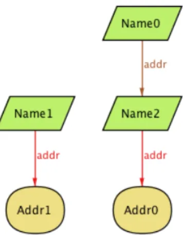
3.2 Address book instance generated by the Alloy Analyzer. . . 44
3.3 Address book instance projected on the Book entity, generated by the Alloy Analyzer. . . 45
4.1 Graphical overview of our approach. . . 47
4.2 Use case meta-model. . . 50
4.3 General structure of action blocks. . . 54
4.4 System sequence diagram meta-model. . . 78
4.5 Interaction overview diagram meta-model. . . 84
xiv List of Figures
5.2 External system sequence diagrams. . . 102
5.3 Flow diagram of the Service Payment use case. . . 111
5.4 Frame schema of the Service Payment use case. . . 112
5.5 System sequence diagram of the Service Payment use case. . . 113
5.6 Interaction overview diagram of the Service Payment use case. . . . 114
6.1 Use case diagram of an Automatic Teller Machine (ATM) system. . 117
6.2 Flow diagram of the Perform Session use case. . . 120
6.3 Frame schema of the Perform Session use case. . . 121
A.1 System sequence diagrams of the Transfer Money and Handle In-valid PIN use cases. . . 151
A.2 System sequence diagram of the Withdraw Money use case.. . . 152
A.3 Interaction overview diagram of the Transfer Money use case. . . . 153
A.4 Interaction overview diagram of the Handle Invalid Pin use case. . . 153
List of Acronyms
API Application Programming Interface
ATM Automatic Teller Machine
CASE Computer-Aided Software Engineering
CSP Communicating Sequential Process
IOD Interaction Overview Diagram
IS Information Systems
IVAL Input Validation
MDA Model Driven Architecture
MDSE Model Driven Software Engineering
OCL Object Constraint Language
OMT Object Modeling Technique
QVT Query/View/Transformation
RUP Rational Unified Process
List of Figures xvii
SPIN Simple Promela Interpreter
SR System Responsibility
SSD System Sequence Diagram
UC Use Case
UD User Decision
UML Unified Modeling Language
XMI XML Metadata Interchange
Chapter 1
Introduction
Throughout the history of software engineering, the development of computer sys-tems has steadily been moving towards increased abstraction. From program-ming in assembly to more tractable languages like C, and then to object-oriented languages such as Smalltalk. Today, models form yet another abstraction layer, resulting in the so-called Model Driven Software Engineering (MDSE).
MDSE brings several advantages to software development. Since it focuses on models rather than lower level algorithms, communication between members of a team and between teams is made easier. Also, the visual nature of some models makes the design process simpler and more intuitive. The communication with stakeholders improves as well, and once there is a solid understanding of the domain, models create a reliable foundation from which to build the real system.
The Unified Modeling Language (UML) emerged in 1997 as an attempt to unify various existing object-oriented modelling languages and to provide a method to use it. Over the years UML has been augmented and detailed, but the method was
left behind [Hru97]. The non-methodical use of UML naturally leads to inaccurate
models and specifications that are, consequently, of little value. UML offers several different models to model different aspects of software systems. Some models
2 Chapter 1. Introduction address structure while others address behaviour or architecture.
The Rational Unified Process (RUP) [Kru03] is a software development
pro-cess that divides the development of a software project in four phases: inception, elaboration, construction, and transition. The work intended for each phase is per-formed in iterations, where the various disciplines such as requirements elicitation, implementation and testing, among others, work together to construct the
deliver-able intended for that iteration (Fig. 1.1). Furthermore, the RUP advocates that
this process should be use case driven, i.e., that requirements should be captured in use cases and the rest of the development process should build upon them.
Figure 1.1: The RUP “hump chart”.
1.1
Motivation
If UML models or diagrams are transformed in a non-systematic way, the situ-ation becomes even more critical since the successive refinements will propagate
1.2. Contributions 3 inaccuracies contained in the models, inevitably leading to wrong implementations.
Furthermore, UML documentation [OMG11] about the textual representation
of use cases, the UML artefact most often used in real practice, is scarce at best. Since it is not standardized, it is possible that different modellers in the same development team have different use case writing styles, which forces subsequent development tasks to be able to interpret and adapt to each style. This is nat-urally error prone and makes the methodical use of UML more difficult. Even if a development team agrees to an internal standard, it is still possible that they benefit from the structuring mechanisms introduced later in this dissertation.
Another common criticism of UML is its lack of formalism. The UML specifica-tion does provide some well-formedness rules for its diagrams in Object Constraint Language (OCL) but many others are mentioned only in natural language. Be-sides, inter-model consistency rules are not mentioned at all. While this level of informality makes the language more flexible and allows some level of customiza-tion for different projects, it also introduces undesired ambiguity which, again, is counterproductive to the systematic and methodical use of the language.
1.2
Contributions
The method envisioned in this dissertation is also based on the RUP´s use case driven ideology but proposes a way to systematically transform use cases into other models. This allows the easy determination of the location and impact of any changes to requirements during the project and, consequently, assures traceability between use case models and other diagrams. Hence, the work developed in this dissertation fits mainly in both the inception and elaboration phases of a software project. First capturing the requirements in use cases and then using them as a solid basis to analyze and design the rest of the system.
4 Chapter 1. Introduction To address the dilemma of uniformity in the use case textual representations we propose a way of identifying the individual action steps with their intention (whether they are input or outputs, etc.) and grouping them within action blocks [HA09,Hel05]. This results in a well structured and defined use case and makes it both easier to think through when writing and clearer to the reader. Furthermore, this lays down the foundation for the model transformation process.
The systematic model transformation process is made possible since some UML models, while each providing a different view of the system, have overlapping ele-ments; i.e., elements that represent the same thing. It is based on these overlapping elements that transformation rules can be derived. In this dissertation, we propose a set of well-defined transformation rules between use cases and system sequence diagrams and interaction overview diagrams. We chose these diagrams because, while each possesses their own strengths and weaknesses, both are natural next steps after the use cases have been constructed.
While systematic, the transformation process is manual. However, in this dis-sertation we also propose using a formalization of the models to support the pro-cess. This allows verifying the intrinsic correctness of the models as well as ver-ifying if a system sequence diagram or interaction overview diagram is a correct derivation of some use case model.
We use Alloy to formalize the models. Alloy is a lightweight formal modeling notation that retains the precision and expressiveness of “classical” formal lan-guages like Z. One of the main strengths of Alloy resides in the Alloy Analyzer, which lets us visualize the model we are building while we are building it, thus promoting an iterative development. This allows modelers to easily detect and rectify defects in the model which otherwise could go unnoticed.
1.3. Outline 5
ref
Legend:
: verifiable in Alloy : transformation rules
Figure 1.2: Graphical synthesis of our contributions.
1.3
Outline
The UML’s problems delineated before are not new. In fact, they have been around since its genesis around fifteen years ago. Hence, there is considerable
research concerning them. In Chapter 2 we give an overview of the work done in
this field and clarify on how the work presented in this dissertation is different.
Next, we introduce Alloy in Chapter 3. We start by explaining its logic and
then the language’s syntax through examples. We conclude that chapter with
an introduction of the Alloy Analyzer. Afterwards, in Chapter 4, we show how
we used Alloy to formalize the aforementioned diagrams and canonical textual
use case representations. Chapter 5 discloses the transformation rules we created
and in Chapter 6 we employ the methodology in the practical scenario of an
Automatic Teller Machine (ATM) system. There, a step by step walk-through on how to correctly apply the transformations rules is given. We then conclude
this dissertation with Chapter 7, where we summarize the work performed and
identify some its limitations at the present stage, though suggesting possible lines of research for future work.
Chapter 2
Related Work
In this chapter, we will discuss the key concepts and previous work that are associ-ated with our study. We begin by introducing UML and its problem of informality
in Section 2.1. In Sections 2.2 and 2.3, different works that seek to address this
predicament are analyzed. In Section2.2we discuss works that focus on the models
addressed by this dissertation and in Section 2.3 we analyze various formal
meth-ods often used in the formalization of the UML, albeit applied to different models: the OCL, the Z notation, graph grammars, the Simple Promela Interpreter (SPIN) tool and Alloy.
2.1
Unified Modeling Language
The UML is a graphical modeling language that allows specifying, visualizing, constructing, and documenting software systems. It has emerged in 1997 with the aim of unifying different modeling languages existing at the time, such as the
Object Modeling Technique (OMT) [RBP+91], Objectory [JCJÖ92] and the Booch
Method [Boo95]. Since then, the UML has become the industry standard by, for
2.1. Unified Modeling Language 7 with complex systems, and allowing the development and abstraction of design patterns.
Despite numerous qualities, the UML has been criticized over the years due to
some of its shortcomings [SG99, FSKdR05]. Among these shortcomings, stands
out the lack of formality of its models. The specification of UML [OMG11] develops
some well-formedness rules intrinsic to each model, but is mute on how to check whether different models are consistent with each other.
The UML diagrams are divided into two groups: structural diagrams and
be-havioral diagrams. Diagrams in each of these groups represent structural or
behav-ioral information, respectively, in different ways and emphasizing different aspects. Although in some instances they are obvious (e.g. the methods referenced in a se-quence diagram must be present in the class diagram), the UML specification is silent when it comes to clarifying this type of relationships.
In this work, we address three distinct behavioral diagrams: use case diagrams, sequence diagrams, and interaction overview diagrams. We seek to establish pre-cise transformation rules between them and verify the rules automatically. Assum-ing the reader is familiar with the UML, this section provides a succinct exposition of these three diagrams placing emphasis only on the strange aspects to the UML specification.
2.1.1
Use Cases
Use cases are a technique for capturing functional requirements of a system without revealing their internal structure. Each use case represents a desired feature for a system through a sequence of messages exchanged between the system and the external entity interested in the functionality, known as actor, whether it is a
person or a computer system [RJB04].
8 Chapter 2. Related Work and with the stakeholders of the project. They are a core part of use case-driven
methodologies, such as the RUP [Kru03], since it is from these that the rest of
the development process unfolds. Additionally, use cases promote the discovery of alternative flows or exceptions to the main flow of the features required for the system, they document the development process, can be used to prioritize work, to quickly discover the gaps between the work completed and the work to be done, and if a properly systematized use case-driven methodology regarding the transformation of models is adopted, when requirements change, it is also possible to know exactly all the artifacts that need to be changed.
While the UML specification [OMG11] only alludes to the use case diagrams
and does not state any way to represent the contents of use cases, these are con-structed by describing the interactions that take place between the actors and the system, typically using a natural language narrative; although state diagrams,
ac-tivity diagrams or interaction diagrams can be used for the same purpose [RJB04].
Use Case Diagrams
A use case is a set of sequences of actions that a system performs to provide a
result of value to an actor [BRJ05]. Use case diagrams assemble use cases and show
the relationship between them and the actors who perform them, indicating which actors perform which use cases. They also illustrate relations exclusive to actors, such as generalization, and relations exclusive to use cases, such as generalization, inclusion, and extension. When we say that generalization is exclusive to both actors and use cases we mean that an actor cannot specialize a use case and
vice-versa. Fig. 2.1 presents an example of a use case diagram.
Include Relation Sometimes, distinct tasks of a system require running a piece
2.1. Unified Modeling Language 9
Figure 2.1: Example of a use case model [Fow03].
would have to be modeled in all use cases that wanted to run it, which could conduct to problems in consistency and maintenance.
The purpose of the include relation is, precisely, to allow the reuse of bits of behavior common to several use cases. This prevents describing the same flow multiple times. The common parts are encapsulated in a new use case that can be included in all the use cases that require the behavior. Another motivation to use include relations emerges when we intend to modularize a design, which happens when, for example, a use case proves to be too large and subdividing it provides reading and management benefits. Here, the use cases are included by just one use case.
Therefore, the include relation is a dependency between two use cases in which one incorporates the behavior defined in the other, in a point specified by the first. As such, the first, called base use case or including use case, is dependent on the second, called included use case, and does not make sense without it. On the other hand, an included use case does not make sense by itself, only in the context of another use case that includes it.
10 Chapter 2. Related Work while running the base use case, it will reach the point of inclusion. The included use case is executed at this stage. When it completes, the base use case is resumed after the inclusion point. Note that the execution of the included use case is not
optional and is necessary for the proper functioning of the base use case [OMG11].
Extends Relation Typically, a use case is not composed only by the description
of the interaction in which everything runs smoothly. There are situations where, for some reason, the system cannot provide the result of value to the actor or needs to go through alternative paths to reach the end of the use case successfully. The alternative paths that a use case can take must be described in its specification as well. However, it is often necessary to provide many alternatives which are sometimes complex. When this happens, there is the risk of the use case becoming difficult to read and maintain. Therefore, the objective of the extends relation is
to allow the separation of conditional behavior from the base use case [BRJ05].
Specifically, extends is a relation between an extending use case and a base use
case, or extended use case, in which the extending use case may append, under
certain conditions, its behavior to the base use case. Thus, the extended use case is independent of the extension use case and has meaning by itself, while the extension use case typically only makes sense within the context of the use case
that extends [OMG11].
Although the extended use case makes sense by itself, under certain conditions its behavior can be augmented by another use case. The points at which the base
use case can be extended are called extension points [BRJ05]. Associated with
each point extension is at least one condition.
Whenever an instance of a use case reaches an extension point, the condition is evaluated. If the condition is found to be true, the associated extension is executed and upon its termination the base use case is resumed; otherwise, the main flow
2.1. Unified Modeling Language 11
continues normally [RJB04].
Because one can describe conditional behavior within a use case, whether to
use the extends relation is at the discretion of the modeler [SP06]. In practice, the
use of the extends relation proves useful when the alternative flows are complex and/or have their own alternative flows, to prevent the base use case from becoming bloated. Analogous to included use cases, extending use cases can extend different base use cases, promoting thereby the reuse of behavior.
Generalization Generalization is the most controversial relationship between
use cases. The basic idea is that a child use case inherits the behavior and meaning from the parent use case, being the child able to append to or rewrite the inherited behavior while also being able to replace the parent anywhere where it appears [BRJ05]. The problem is that it has not yet been reached a consensus on how to take advantage of this concept, nor is it clear what is meant to specialize behavior
[Coc00, WKKP05, Lar04]. Consequently, many authors argue that one should
not use the generalization of use cases to avoid any confusion due to different interpretations of this relationship.
Anyhow, the purpose of generalization relationship is to model situations where
a given task can be accomplished in different ways. Fig. 2.2 provides an example
of generalization.
Pay by credit card Pay by cash
Pay
Customer
Figure 2.2: Example of generalization between use cases.
12 Chapter 2. Related Work the children may append new actions to (contiguous or not) or replace inherited
actions [RJB04]. However, in the context of this dissertation, we will follow the
indications given by Cockburn [Coc00], who suggests leaving the parent use case
empty and specifying all the behavior in children use cases, keeping in mind that both should have the same goal.
Textual Use Cases
Textual use cases consist of the specification of a set of actions performed between actors of a system and the system itself, with the aim of providing a result of value
to the actors [OMG11, Fow03]. It is these specifications that detail the
actor-system dialogue of the use cases presented in the use case diagram. Common
representations of these specifications include mono-column (Fig. 2.3) and
dual-column narratives, where the actions performed by the actor and the system are segregated and represented in their own column.
Figure 2.3: Example of a textual specification of a use case [Fow03].
2.1. Unified Modeling Language 13 diagrams. However, it does not state how to organize their content, the textual specifications, or the way it relates to the diagrams. In practice, though, use cases have been specified using sequence diagrams, Petri nets or programming languages,
but the most usual is the use of natural language [Coc00].
Considering that use cases serve as a means of communication between peo-ple, often without technical training, a textual format is possibly the best choice [Coc00]. Nevertheless, natural language can lead to ambiguities, making multiple interpretations possible as well as hampering their writing and understanding.
In an approach to this dilemma, Heldal [Hel05] introduced the notion of
ac-tion block. Action blocks group action steps, the steps constituting the textual
specifications of use cases. This grouping is based on the interpretation given in
Cockburn [Coc00] of the concept of transaction created by Jacobson [JCJÖ92].
Specifically, action blocks are composed of: (1) an input made by the actor, (2)
validation of the input, by the system, (3) a change in the state of the system and,
finally, (4) the response given by the system to the actor with the result of the
operation (Fig.2.4). The input step marks the beginning of any action block, but
the remaining steps can form any subset of the other steps adverted to, provided they maintain the order described.
Actor
System
1. Request with data
4. Respond
2. Validate
3. Change
Figure 2.4: General structure of action blocks.
Further research concluded that the validation step was not flexible enough
14 Chapter 2. Related Work Assume steps are not restricted to the second position in the flow of action blocks and can arise after a change of the system’s state. Thus, they act not only as a validation step of the user’s input but can also check the result of internal
operations. Moreover, in Helldahl and Ashraf [HA09], the authors restricted the
origin of alternative flows to assume action steps. In Chapter 4.1.1 we argue that
the concept of assume steps can still be ameliorated and present our contributions to the development of this concept.
Another possibility for structuring use cases is to classify them according to
their goal. Cockburn [Coc00] contemplates three levels for the classification of
goals of use cases: summary, user-goal, and sub-function. Summary level use cases represent high-level business processes and involve the execution multiple instances of user-goal level use cases. These, in turn, represent tasks that provide a result of value to the actor and may depend on the execution of sub-function level use cases, which represent support operations to upper level use cases and do not constitute, by themselves, an action of value for the actor. In this work, we will only consider the user-goal and sub-function levels.
Besides classifying use cases it is also possible to classify the flows from which they are built. Each use case is composed of a main flow and, potentially,
al-ternative flows. The main flow corresponds to the most common route that the
actor-system dialogue takes to provide a result of value to the actor [SCK09].
Alternative flows may represent exceptions [MOW03, KG03, AM01], alternative
stories [MOW03], conditional insertions [JCJÖ92, AM01, Coc00, KG03, Sim99],
cycles [MOW03] or alternative fragments [MOW03].
Some authors use the term extensions to encompass all these types of flows. However, this term can cause confusion resulting from the extends relation pro-vided by the UML specification. Hence, we use the term alternatives with the same intention.
2.1. Unified Modeling Language 15
2.1.2
System Sequence Diagrams
System sequence diagrams represent use cases graphically. They denote the actor and the system, messages exchanged between them and in which order, and the origin and destination of each message. The system, in this type of diagrams, is treated as a black box, which puts the emphasis on the actor-system interaction [Lar04].
To see the system as a black box forces us to think about the interface of the system, i.e., the things that it will be able to do. Instead of fretting, at an early stage of the software development, on how it will do them; in the same way that when we design a class, we do not think, initially, about how to implement the methods of its Application Programming Interface (API), but only to define the API. It is in this context that the usefulness of the system sequence diagram can be appreciated. To clarify the concept of system sequence diagram, one is illustrated
in Fig. 2.5.
Figure 2.5: Example of a system sequence diagram [Lar04].
A system sequence diagram is contained within a rectangular frame with its name on the top left corner and is divided into two columns, designated as lifelines; one to represent the actor, denoted by a stick figure, and the other to represent
16 Chapter 2. Related Work the system, denoted by a box with the name of the system in it. The interaction specified in use cases is, in system sequence diagrams, transformed into messages exchanged between the actor and the system. These are represented by horizontal arrows departing from the lifeline that sends the message and end in the lifeline that receives it.
System sequence diagrams support various constructs for control flow. Con-ditional behavior of the types if-then or if-then-else, loops and exceptions can be modeled via combined fragments. These fragments correspond to rectangular frames with a label indicating what type of control flow structures they represent in the upper left corner. Some fragments can be subdivided. Conditionals of the type if-then-else, for example, are represented in a fragment with several segments, called operands, divided by a dashed line.
The UML specification offers several types of combined fragments. However, in this work, we will work with only four:
alt: The purpose of this combined fragment is to model if-then-else structures.
It may contain multiple operands, each having a guard condition. Only the one whose guard evaluates to true and executed.
break: The break fragment has only one operand and one guard condition. If the
guard is false, the operand is ignored and execution continues normally; oth-erwise, the operand is executed but the rest of the diagram is not. Typically, this fragment is used for exceptional situations in which the task is aborted when some condition is met.
loop: The loop frame models cycles and has one operand and one guard condition.
The operand is executed as long as the guard evaluates to true. Its semantics is similar to the while loop of programming languages like Java or C.
con-2.1. Unified Modeling Language 17 tains one guard condition and one operand. Its semantics is analogous to the fragment break with the distinction that, if the condition is true, execution of the rest of the sequence diagram is resumed and after the execution of the operand.
2.1.3
Interaction Overview Diagrams
Albeit sequence diagrams have control flow structures, its primary purpose is to visualize how the various entities of a system cooperate to perform some task. In fact, if the flow of a task is comparatively complex, i.e., with several alternative paths, the corresponding system sequence diagram will be difficult to read due to the large number of frames that will be necessary.
A more suitable way to visualize complex flows involves the construction of interaction overview diagrams. Interaction overview diagrams mix the notation of activity diagrams with bits of sequence diagrams. The sequence diagrams illus-trate linear interactions between actor and system, while the notation of activity diagrams that handles control flow deals with alternative paths and cycles.
Concretely, interaction overview diagrams are a specialization of activity dia-grams in which the nodes correspond to sequence diadia-grams or embedded references
to external sequence diagrams [GCP+05]. The execution of the diagram begins
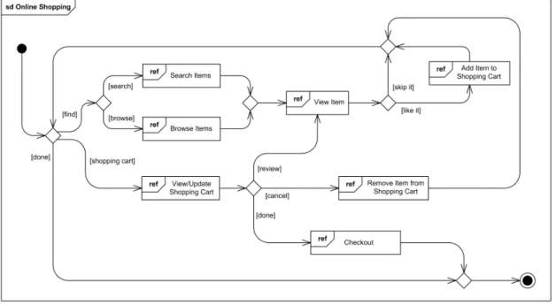
with the initial node, then follows the arrows and executes each node until it reaches the final node. The alternative paths, which in sequence diagrams are represented by the combined fragments, in the interaction overview diagram are modeled through decision-nodes. These contain guard conditions corresponding to each of the flows and according to the evaluation of the guard, the corresponding flow is executed. An interaction overview diagram delineating the process of online
18 Chapter 2. Related Work
Figure 2.6: Example of an interaction overview diagram1.
2.2
Transformation and Consistency of UML
Models
One of the strengths of UML is its wide range of models that allow us to approach a software system from different perspectives. However, this is also the cause of one of its most studied problems: inconsistency.
Inconsistency problems arise when, as a software system is being developed resorting to a methodology based on model transformation, successive transfor-mations and refinements dilute the significance of the initial models, eventually contradicting each other.
Inconsistent models may cause problems in the implementation [MBC05], in
their management [KHR+03] and make it impossible to generate code through the
models [SB05], a privileged process in MDSE.
2.2. Transformation and Consistency of UML Models 19 To overcome these issues it is necessary to employ techniques to ensure the consistency of UML models. This need becomes apparent if we analyze the amount of published work in this area in recent years, whether in journals,
work-shops [KHRS02,KHR+03,KHR+04] , or conferences. Thus, model transformation
and consistency are two closely related topics [EB04]. If, on one hand, without
a notion of consistency, the models can be freely transformed, the lack of trans-formation rules between two models (for lack common concepts), means that it makes no sense to speak of consistency between them.
2.2.1
General Terms
To better understand the area under study, it is important to clarify some of its key concepts such as model, model transformation, transformation rules, intra-model
consistency and inter-model consistency.
Model A model is an abstraction of something, in which important aspects of
the object being modeled are captured and aspects seen as less relevant are omitted or simplified. Software systems are modeled through modeling languages such as UML, where they are represented by diagrams and text. The model should be able
to answer questions instead of the real system and be easier to use [BG01,RJB04].
Model Transformation Model transformation involves the construction of a
target model from a source model according to a set of transformation rules. This
definition is akin to that given in Kleppe et al. , e[KWB03]xcept the
transfor-mation in that work is considered an automatic process, whereas in this work the transformation will be performed manually.
Transformation Rule A transformation rule is a description of how the source
20 Chapter 2. Related Work
Intra-Model Consistency Property of a model when it conforms to its
meta-model and respects all the rules imposed on it [EB04].
Inter-Model Consistency Property observed between a source model and a
target model when, by applying the transformation rules corresponding to the two
models, from the source model it is possible to derive the target model [EB04].
2.2.2
Consistency Approaches
Because the literature about the UML consistency is quite extensive, it is possible to find many different approaches to this problem, formal and informal. Within the group of approaches that use formal techniques there are authors who make use of, for example, graphs, petri nets, Z, B, Communicating Sequential Process (CSP) or description logics.
In this work, we will consider transformations of use cases to sequence diagrams and use cases to interaction overview diagrams. So, in this section, we will pay special attention to literature that focuses on these specific diagrams, leaving to
Section 2.3 a discussion of different approaches concerning the formalization of
UML which work with other diagrams.
One possible way to accomplish the transformation between use cases and
sequence diagrams is based on natural language processing [YBL10,SHH07,Li00].
Yue et al. [YBL10] presents an approach and a tool that perform the automatic
generation of sequence diagrams from use cases. However, the transformation is also based on class diagrams and the operations depicted therein. In addition, generated sequence diagrams are not system sequence diagrams and the writing of textual use cases is constrained with the use of keywords (e.g. if, then, else,
meanwhile) to define the flow of the use case. The tool presented in Segundo
2.2. Transformation and Consistency of UML Models 21 be able to do the language processing. It accepts only specifications in Spanish and its grammar rules, not referring under which circumstances the characteristic
sequence diagrams’ frames are used or even if the tool supports them. Li [Li00]
resorts to the use of keywords to write the flow of use cases as well. The presented approach is semiautomatic, requiring user input to translate certain parts of the use cases. Like Second et al., it makes no mention of the use of frames.
Furthermore, the application of approaches making use of natural language processing is inherently limited to environments in which the language for which they were developed is used, thus hampering widespread adoption.
Apart from approaches based on natural language processing, other solutions
were sought by different authors. In Almendros-Jimenez and Iribarne [AJI07] an
approach based on several steps was carried out: first, a use case diagram repre-senting the basic tasks of the system is developed; then, the behavior of use cases is detailed resorting to sequence diagrams and encapsulating some bits of behavior in sequence sub-diagrams; and finally, these sequence sub-diagrams are mirrored in the use case diagram where they represent the inclusion and extension of use cases. However, this approach does not use textual specification of use cases, im-portant artifacts to communicate with stakeholders. In Mason and Supsrisupachai
[MS09], it is presented a tool where one can write the textual specifications of
use cases and label certain words as being the sender, receiver, or the message, including parameters. This approach bypasses the linguistic limitation and allows the unrestrained description of use cases but the cost of an intrusive technique that impairs the readability of use cases. In addition, this paper does not mention any of the characteristic sequence diagrams’ frames as well.
As far as the transformation from use cases to interaction overview diagrams goes, literature is rather scarcer. The interaction overview diagram is a new type of diagram that emerged only with the UML 2.0 and its optimal use is still to be
22 Chapter 2. Related Work
understood. Nevertheless, Garcia et al. [GCP+05] presents a use case diagram
and the corresponding interaction overview diagram in different phases; i.e., first considering simple diagrams without inclusion or extension relationships and then elaborating on that by incorporating them. However, no kind of systematic rules to perform this transformation is indicated.
Regardless, before one can talk about inter-model consistency, it is necessary that the individual models are in accordance with their well-formedness rules. The starting point for the definition of well-formedness rules is the UML specification
[OMG11]. Therein some rules are provided by using OCL [OMG10] or natural
language for each diagram. The use of natural language to define the semantics of the diagrams provides greater flexibility for modelers because they can be inter-preted in different ways and allow the application of the diagrams in completely different contexts. However, when attempting to formalize the rules, this form of presenting them is counterproductive.
Consequently, some authors addressed this question by using more rigorous
methods to formalize the rules. In Ibrahim et al. [IIS+10] the authors defined and
formalized well-formedness rules for use case diagrams using set theory, but did not indicate or use any mechanism for the automatic verification of their correctness.
In contrast, in Ballur and Vallieswaran [BV06], it is presented a tool for checking
the consistency between design and code where some well-formedness rules are presented for use case diagrams and for system sequence diagrams, among others. However, it does not address the extends, include or generalization relations.
2.3
Formal Methods
“The nice thing about graphical description techniques is that every one under-stands them, the bad thing, however is that every one underunder-stands them in a
dif-2.3. Formal Methods 23
ferent way.” This is the problem of notations such as UML and where the
appli-cation of formal methods can bring significant advantages, by making explicit and unequivocal the semantics of the notation.
Formal methods is a set of mathematical languages, tools and techniques for the specification and verification of software and hardware systems. It is particu-larly useful in critical and/or large scale systems in which a small error can cause great losses of money, time, or even human lives. Albeit formal methods cannot guarantee 100% correction of the system, its aid in the discovery of inconsistencies, ambiguities and incompleteness, allows for the elaboration of models with greater
reliability and robustness [CW96].
In this section, we will review the formal methods that are most often applied in the formalization of UML. We will highlight some of the characteristics of each approach and conclude with the justification for choosing Alloy as our model checking language in this work.
2.3.1
OCL
OCL [OMG10] emerged along with UML as the formal language to describe
ex-pressions on its models. Typically, these exex-pressions represent invariants of the model or queries that can be performed on it, bearing in mind that the evaluation of those does not produce any side effects, i.e., it is not possible to change the state of a system through OCL.
Chiorean et al.[CPC+04] uses the XML Metadata Interchange (XMI) standard
for transferring consistent models from the Object Constraint Language
Envi-ronment2 checking tool to another UML tool, and vice versa. Besides detecting
inconsistencies, the tool is also able to correct them. As in this dissertation, the consistency rules are defined at the meta-model level, making them independent
24 Chapter 2. Related Work from the user’s models. However, the authors expound only the well-formedness rules and do not allude to issues of inter-model consistency.
On the other hand, in Bodeveix et al. [BMP+02], consistency rules between
models are established. The authors discuss the consistency between class dia-grams and sequence diadia-grams, class diadia-grams and object diadia-grams, class diadia-grams and state diagrams, and between sequence diagrams and state diagrams; but ignore interaction overview diagrams and use cases, the core diagram in this dissertation.
2.3.2
SPIN model checker
Simple Promela Interpreter (SPIN) [Hol04] is an open-source model checking tool
and is particularly suited for concurrent systems. As the acronym suggests, the models are specified using the Promela language and are also executable. The model checker allows the simulation and exhaustive analysis of the behaviors spec-ified.
The SPIN model checker is used in Zhao et al. [ZLQ06] to check the consistency
between sequence diagrams and state diagrams. The state diagrams are mapped to the formalism of split automata to deal with the hierarchical states characteristic of these diagrams, which contributes to the efficient passage of these diagrams to SPIN since their semantics are analogous to that of processes in Promela. In addition, they can prove that the translation of UML models to the model checker is correct and that the model translated truly represents the UML model.
2.3.3
Z
Z notation [WD96] is a language based on mathematical set theory and
mathe-matical logic. The combination of the Z notation with natural language allows the creation of formal specifications, which can be reasoned with by using proof
2.3. Formal Methods 25 techniques of mathematical logic. These specifications can be refined successively, getting closer to final code at each iteration.
Amalio et al. [ASP04] outlines an approach to formal analysis of UML models
through a formal representation in Z. The authors advocate the use of modeling frameworks for the construction and analysis of domain-specific models. Each framework consists of several UML diagrams whose semantics is made explicit in any formal specification language and where the analysis is performed using the methods available for the chosen language. Thus, the authors intend to make development in UML more precise, avoiding the need for modelers to have a thor-ough cognition of formal languages and thereby making the development of sound systems more practical. As an example of their methodology, the authors use Z as the formal specification language for describing the semantics of class diagrams, objects and states.
2.3.4
Graph Transformation
Graphs are a widely used structure in software engineering by allowing to explain complex problems in a natural way. At the heart of graph transformation is the rule-based modification of graphs. Each rule consists of a pair of graphs, 𝐿 and
𝑅. Applying this rule to a graph consists of finding on this graph a sub-graph
corresponding to 𝐿 and replacing it with 𝑅 [EEPT10]. The nature of the graph
naturally lends itself to class and object diagrams and to the representation of system states, important artifacts when modeling in UML. Consequently, with the advent of model transformation in model driven development processes, graph transformation appears as a natural choice for its formalization.
Wagner et al. [WGN03] presents a flexible and incremental consistency
man-agement framework for the open-source Computer-Aided Software Engineering (CASE) tool Fujaba. The framework allows the user to specify consistency rules
26 Chapter 2. Related Work through a formalism based on graph grammars, which allows customization of rules for different projects or domains. However, only model well-formedness issues are mentioned and not their inter-model consistency.
On the other hand, an attempt to integrate different UML models was
con-ducted in Kuske et al. [GKZ09]. The authors used the formalism of graph
transfor-mation to provide an integrated semantic base for these. Specifically, the authors considered class diagrams, sequence diagrams, object diagrams, state diagrams, and collaboration diagrams. Despite making an effort to integrate more diagrams than other works of the same genre, similarly to those, use case diagrams and interaction overview diagrams are left out.
2.3.5
Alloy
Alloy is a formal language based on OCL and Z, combining OCL’s emphasis on bi-nary relations and the navigational way of expressing constraints with Z’s simpler
semantics [Jac00]. It retains the characteristics of formal notations such as
preci-sion and expressiveness, but adopts an automatic mechanism for the verification of specifications instead of theorem proving, typical of other formal approaches.
Alloy is discussed in more detail in Section3.
Using Alloy, in Nimiya et al. [NYM+10], the authors address the consistency
between state diagrams and communication diagrams. They use a methodology analogous to the one used in this dissertation, starting by defining the models’ entities and then building an instance, using assertions and predicates to validate it. Given the similarities, this article is a probable reference for potential extensions to the work of this dissertation if state and communication diagrams were to be addressed.
Class diagrams enriched with OCL constraints and corresponding
transfor-2.3. Formal Methods 27 mation is based on Model Driven Architecture (MDA) techniques and is intended to allow the analysis of class diagrams. The paper also addresses the challenges inherent to this transformation which arise due to fundamental discrepancies from Alloy’s and UML’s design, such as the lack of support for multiple inheritance in Alloy.
Shah et al. [SAB09] performed a study involving the UML2Alloy3 tool. This
tool performs the transformation of class diagrams enriched with OCL constraints to Alloy, to be able to analyze such models. In this work the authors present a new transformation that translates instances generated by Alloy into UML object diagrams, implementing the technique through the Query/View/Transformation (QVT) standard.
Barajas [Bar06] develops a formal specification for a tool that models system
requirements through use cases. Specifically, a possible use case modeling in Alloy is presented, akin to that sought in this dissertation. Some of the definitions presented in the study were reused here, while others were discarded because of different interpretations regarding the semantics of relations between actors and use cases.
In Kelsen and Ma [KM08], the authors argue that Alloy is a good approach
to formalizing modeling languages. The study compares several alternatives and concludes that the greatest advantages of Alloy are a uniform notation and au-tomated analysis. These are the reasons that guided us to electing Alloy for the development of the consistency mechanism presented in this dissertation.
28 Chapter 2. Related Work
2.4
Conclusion
In this chapter, we explained the value of the application of formal methods as complement to less formal modeling languages like UML. They consist of a set of languages, tools and mathematical techniques which are particularly suitable for critical or large scale systems’ design. We discussed several formal methods, such as OCL, the Z notation, the SPIN tool, graph grammars and Alloy, which are often used in UML formalization and how studies using these methods were related to the work proposed in this dissertation. We found that albeit the liter-ature is extensive, relatively few works address the formalization of use cases and interaction overview diagrams. This justifies the need for a research as the one developed in this dissertation. Finally, we selected Alloy as our modeling language because of its simple notation and powerful automatic analyzer.
Chapter 3
Alloy
Despite the advantages of formal methods, its application in the industry has
been limited [Kne97]. This has conducted to the emergence of formal methods
whose emphasis is on the partial and focused application of the formalization, the
so-called lightweight formal methods [JW96].
Alloy [Jac12] fits into this new type of formal methods but retains some of the
qualities recognized to traditional formal methods such as precision and expres-siveness. The main distinction between these two kinds of formal methods consists in the use of a mechanism for automatic analysis instead of analysis based on theo-rem proving. The disadvantage of this mechanism is its limited space of examined cases, while the theorem proving provides a valid response to any element within the spectrum of possible cases (which may be infinite). Nevertheless, the number of cases analyzed is in the order of billions and thus considerably higher than the
degree of coverage achieved with testing [Jac06].
The models specified in Alloy are typically small (micromodels), analyzable,
declarative, and structural [Jac02].
They are typically small because it is possible to study properties of a complex system with few lines of code, the language itself is simple and small, and the focus
30 Chapter 3. Alloy is on formalizing only the parts of a system that really should be formalized, either because they present substantial complexity or because they support processes whose failure could cause considerable losses.
Alloy allows its models to be analyzed in two ways: simulation and verification. Simulation is based solely on the model and generates possible instances, allowing us to conclude whether the model is consistent or not. Verification requires as input some property that the modeler wants to check. If the model does not possess that property, Alloy produces a counter-example; i.e., an instance of the model where the property does not hold.
The Alloy language is also declarative. Models constructed using this paradigm allow the modeler to focus on communicating what happens when some operation is performed instead of worrying about how it happens. In state-based languages like Java or C, the programmer explicits the way to reach some state from another, while in declarative languages (like Prolog or Haskell) the focus is on stating how the initial and final states are connected.
Software systems are composed of two fundamental elements: structure and behaviour. There are several analysis tools for the behavioural part; however, Alloy is one of the first to approach the structural component. Alloy allows the definition of complex structural relations between the various entities belonging to the problem’s domain so that one may then reason about their properties.
Unlike UML, which is a visual modelling language, Alloy is mainly text-based. Alloy models are composed of signatures, facts, predicates, assertions, functions and commands. Domain entities are introduced in Alloy models via the signature construct. Each signature is allowed to have a set of properties, effectively relat-ing them with other signatures. Constraints can be applied to these relations to restrain the way signatures may associate with each other. In Alloy, these con-straints are introduced via facts, which represent properties that the model must
3.1. Atoms and Relations 31 possess; or via predicates, for when we want to analyze a model with and without a certain property. Predicates also allow, like functions, to package expressions for reuse in different contexts. The difference is that predicates evaluate to either true or false while functions return a value of a type defined by the modeler. Assertions allow us to verify if some property follows from the facts of the model and the commands are used to analyze the model.
In the remainder of this chapter, the core aspects of Alloy will be explained in greater detail. Specifically, its underlying logic and the relational perspective with
which one can read Alloy models (Section 3.1), the other two perspectives, i.e.,
object-oriented and set theoretic (Section 3.2), the Alloy language (Section 3.3)
and its analysis mechanism (Section 3.4).
3.1
Atoms and Relations
The structural component of a software system consists of the entities belonging to the problem’s domain and the way they relate to each other. In Alloy, these correspond to atoms and relations, respectively.
Atoms are characterized for being indivisible, immutable, and uninterpreted. The fact that atoms are indivisible means that they cannot represent, for example, tuples, as they are divisible. The immutability property signifies that it is not possible to alter the properties of an atom, and being uninterpreted means that atoms do not possess any properties by default, contrary to numbers, for example. To model divisible, mutable, or interpreted concepts, relations are used. Rela-tions associate atoms with one another, creating tuples which may be of any arity equal to or greater than one. The arrangement of atoms in each tuple is relevant and unary relations (i.e., with arity equal to one) simply represent sets of atoms. A unary relation composed of a single atom is a scalar.
32 Chapter 3. Alloy Relations can be manipulated via set operators and relational operators. The former are utilized when it is intended to work with the relations as if they were just sets of tuples. On these occasions, the structure of the relations’ tuples is irrelevant and may be seen as sets of atoms. On the other hand, the structure of the tuples is essential to the latter operators, which take full advantage of the power of relations.
Set operators are based on those of set theory, namely: union (+), intersection (&), difference (-), subset (in) and equality (=). Though the structure of the tuples in this type of operations is irrelevant, these operators can only be used between relations with the same arity.
Relational operators are based on relational logic and they are responsible for making relations such a powerful mechanism. Alloy possesses the following rela-tional operators: product (->), dot join (.), box join ([]), transpose (~), transitive
closure (^), reflexive-transitive closure (*), domain restriction (<:), range
restric-tion (:>) and override (++).
There is still a third group of operators: logical operators. These operators are used to combine expressions to form more complex restrictions. They are identical to those of boolean logic and each one has two possible representations: negation (not, !), conjunction (and, &&), disjunction (or, ||), implication (implies, =>),
alternative (else, ,) and bi-implication (iff, <=>).
Besides operators, Alloy also introduces some constants. The constant univ represents the set containing every atom of the model, none is the constant which does not contain any atom and the iden denotes the binary relation where each atom is related to itself.
3.2. Object-Oriented and Set Theoretic Views 33
3.2
Object-Oriented and Set Theoretic Views
Although atoms and relations reflect the true semantics of the Alloy language, when reading Alloy models one tends to think in a more abstract manner. Namely, Alloy code can be read as if it were object-oriented, which is the highest level of abstraction at which one can read Alloy code, or one can think in set theoretic terms. Actually thinking of Alloy models as atoms and relations is not usually done even by advanced users.
Entities defined in Alloy models can be seen as being classes, and the relations defined in such entities may be seen as being the classes’ fields. Also, the dot join operator allows producing code similar to that of object-oriented languages, which further contributes to reading models in this manner. Interpreting Alloy models in this object-oriented fashion aids in rapidly understanding a model, but may be dangerous without a deeper understanding of Alloy, as its level of abstraction may fail to explain some of the intricacies of the Alloy language.
Thus, it is usual to think of Alloy models in set theoretic terms. Here, the entity definitions in Alloy models are regarded as sets, and individual entities (or instances, in object-oriented terms) are their elements. The relations defined in the entities are now read as mapping the corresponding entity to other entities of the type defined in the relation, which constitutes a lower abstraction level of thinking about Alloy models but which is more in line with its true semantics.
3.3
Language
In this section, we present the main characteristics of the Alloy modeling language. The syntactical constructions considered most relevant will be presented through small examples. Concretely, we will see how to introduce signatures, facts,
34 Chapter 3. Alloy via the invocation of predicates and assertions.
3.3.1
Signatures
The aim of signatures is to model the entities that exist in the problem’s domain, and they represent sets of atoms (or classes, in an object-oriented view). For example, the declaration
sig A {}
introduces the set A in the model.
Similarly to object-oriented programming languages, Alloy also supports in-heritance mechanisms
sig A1 extends A {} sig A2 extends A {}
The signatures A1 and A2 are both subsets of A in which the elements of one subset are not present in the other; i.e., the signatures A1 and A2 are mutually exclusive.
It is also possible to create abstract signatures by using the keyword abstract: abstract sig B {}
Abstract signatures contain no elements by themselves. Thus, they are of value to a system only when they are extended, at which point they encompass all the elements belonging to their subsignatures.
Alloy further allows the restriction of the number of elements a signature may have, sufficing to precede the keyword sig by a multiplicity keyword. For example, the declaration

![Figure 2.3: Example of a textual specification of a use case [Fow03].](https://thumb-eu.123doks.com/thumbv2/123dok_br/17758890.835362/30.892.181.657.631.930/figure-example-textual-specification-use-case-fow.webp)