Perfectly conducting loop of wire moving through a uniform
and stationary magnetic field
(O movimento de uma espira condutora perfeita atrav´es de um campo magn´etico estacion´ario e uniforme)
Fernando L. da Silveira
1, Ives S. Araujo
1, Maria C. Varriale
2, Luiz F. Ziebell
11Instituto de F´ısica, Universidade Federal do Rio Grande do Sul, Porto Alegre, RS, Brazil 2Instituto de Matem´atica, Universidade Federal do Rio Grande do Sul, Porto Alegre, RS, Brazil
Recebido em 4/4/2012; Aceito em 23/6/2012; Publicado em 18/2/2013
A conductive loop of wire moving with constant velocity in a magnetic field is one of the most used examples in physics textbooks in connection to the Faraday-Lenz law, highlighting the consistency of electromagnetism with the principle of conservation of energy. It is frequently concluded that currents are not induced in a perfectly conducting loop because an induced current would have to be infinite and therefore would violate the principle of energy conservation. In this paper we discuss this problem and show that a model that includes the loop self-inductance prevents the divergence of the current and leads to results compatible with the conservation of energy.
Keywords: Faraday-Lenz law, auto-inductance, electrical resistance, perfect conductor.
Uma espira condutora movendo-se com velocidade constante atrav´es de uma regi˜ao com um campo magn´etico
constitui-se em uma das situa¸c˜oes mais utilizadas em livros did´aticos de f´ısica em conex˜ao com a lei de Faraday-Lenz, servindo para evidenciar a consistˆencia do eletromagnetismo com o princ´ıpio da conserva¸c˜ao da energia. Da an´alise dessa situa¸c˜ao ´e frequentemente extra´ıda a conclus˜ao de que correntes n˜ao s˜ao induzidas em espiras perfeitamente condutoras porque nestas uma corrente induzida teria de ser infinita e portanto violaria o princ´ıpio de conserva¸c˜ao de energia. No presente artigo apresentamos uma discuss˜ao sobre este problema e mostramos que um modelo para a espira que inclua sua autoindutˆancia n˜ao apresenta divergˆencia da corrente e leva a resultados compat´ıveis com a conserva¸c˜ao da energia.
Palavras-chave: lei de Faraday-Lenz, autoindu¸c˜ao, resistˆencia el´etrica, condutor.
1.
Introduction
The electromagnetic (EM) theory, set forth in the XIX century as a coherent body of knowledge, is one of the greatest intellectual achievements of the human history. It unified electrical and magnetic phenomena, settled the ground for the understanding of the light as an electromagnetic wave, and lead to the conception that EM waves do not need a material support in order to propagate. Significant part of our present technology is directly related to practical applications of the EM theory, and the understanding about the inner works of any electronic product requires basic knowledge of fun-damental concepts of the EM theory. The theory deals with vector fieldsEandB, which satisfy a set of math-ematical laws known as the Maxwell laws, which are
extensively studied in undergraduate courses in physics and engineering. However, despite the usual emphasis on the study of these very important laws of natural science, some features remain insufficiently explored in textbook treatments.
In the present paper we discuss some of these insuf-ficiently explored features, related to a simple example which is usual in textbooks on electromagnetism as il-lustration of the relationship between the time varia-tion of the magnetic flux through the area limited by a closed circuit and the induced eletromotive force (emf). The example considers a rectangular conducting loop of wire, with sideshandwand electrical resistanceR, moving with constant velocityvthrough a rectangular region abcd, which is perpendicular to a uniform and stationary magnetic fieldB(Fig. 1).
1E-mail: [email protected].
Conducting loop
h
w
v
a b
d c
B
X X X X X X X X X
X X X X X X X X X
X X X X X X X X X
X X X X X X X X X
X X X X X X X X X
X X X X X X X X X
X X X X X X X X X
X X X X X X X X X
Figure 1 - Conducting loop of wire before entering a region with uniform and stationary magnetic field.
It can be easily shown that an induced emfεoccurs in the loop, starting when it initiates the penetration in theabcdregion and vanishing when it is completely inside this region. The emf starts again when the loop starts to leave the abcd region and vanishes when it leaves the region. The absolute value of the emf is
|ε|=Bhv , (1)
and the intensity of the induced electric current is
|i|= Bhv
R . (2)
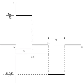
Figure 2 shows the induced current as a function of the position of the leading side of the moving loop, consideringx= 0 the position in which the loop starts the penetration of theabcdregion, andx1=abthe
po-sition in which the loop starts to leave this region. The magnitude of the current is the same in the entrance and in the exit phases, but the sense of the current is inverted, as described by the Lenz law.
O x
i
x 1
w
w
ab B h v
R
B h v R
-Figure 2 - Induced current as a function of the position of the leading side of the moving loop, in the case of a purely resistive loop.
As a consequence of the induced current the loop suffers a magnetic force whose magnitude is given by
|FB|=
B2h2v
R , (3)
both in the entrance phase and in the exit phase. The magnetic force is opposite to the sense of motion of the loop, in both phases. For the movement of the loop to be maintained at constant speed, some agent external to the system loop+magnetic field must apply a force of the same magnitude as the magnetic force, but in op-posite sense. That is, the external force must point in the same sense as the velocity of the loop. The external agent therefore introduces power into the system, given by
PF =
B2h2v2
R . (4)
On the other hand, power is dissipated in the loop, by the so-called Joule effect, in an amount given by
PR=Ri2=
B2h2v2
R . (5)
These results show that the power introduced into the system by the external agent, given by Eq. (4), is exactly the same as the power dissipated by Joule effect, given by Eq. (5). The conclusion, always emphasized by the textbooks, is that the Faraday-Lenz law is con-sistent with the principle of energy conservation.
This textbook example clearly shows that the duced currents, the forces and the powers involved, in-crease when the electrical resistance of the loop is re-duced. An interesting variation of the situation can therefore be proposed: What happens if the electrical resistance of the loop is reduced until vanishing, that is, if the loop is made from a perfectly conducting ma-terial?
Well known textbooks discuss this limiting situation using arguments which may be understood erroneously, if interpreted as simple extrapolation of the result given by Eq. (2). For instance, in the book by Tipler and Mosca (2004, p. 923) [1]:
. . . there can be no electric field in a super-conducting ring because it has no resistance, so a finite electric field would drive an infi-nite current. The flux through the ring is thus frozen and cannot change.
Similar statement can be found in the book by Chabay and Sherwood (2010, p. 963-964) [2]:
Statements like these may easily appear to have been obtained by direct use of Eq. (2). However, Eqs. (2) to (5) are not strictly valid when the electrical resistance becomes very small, leading to divergence in the limit of vanishing resistance. The divergence does not occur in the physical phenomena, it is rather con-sequence of the use of a model which does not take into account the inductance of the loop. In the following sections we discuss some particular cases and demon-strate that the divergences in Eqs. (2)-(5) do not occur if a more complete model is utilized for the descrip-tion of the loop. For the analysis, we assume that the emission of electromagnetic radiation is negligible in all cases considered.
The problem of the conducting loop, either resis-tive or with vanishing resistance, taking into account the self-inductance, has been discussed in a paper by Saslow [3], which develops and discuss the pertinent differential equations. Another and more recent analy-sis appears in Ref. [4], which discusses the occurrence of self-inductive effects in the context of perfectly conduct-ing and superconductconduct-ing circuits, rather than resistive circuits, and intends to be useful to motivate the inter-est of students on the topic of superconductivity. The present paper adopts a perspective somewhat comple-mentary to that of Ref. [4]. It does not intend to discuss the superconducting state, but offers a detailed discus-sion on the transition between circuits which can be considered as purely resistive and circuits with vanish-ing resistance, with the discussion restrained to the use of concepts which are usual in general physics classes. The approach which is proposed in the present paper avoids the use of second-order differential equations, re-lying instead on a mathematical approach more con-sistent with that of textbooks on general physics, like those already mentioned [1, 2].
The structure of the paper is the following: in sec-tion 2 we discuss the case of a conducting loop of wire moving with constant velocity, taking into account the self-inductance and the resistance of the loop. In sub-section 2.1 we present the limiting case of a per-fectly conducting loop, still taking into account the self-inductance. The transition between the perfectly con-ducting case, in which the resistance vanishes and the self-inductance can not be neglected, and the opposite case in which the self-inductance is negligible and the loop can be considered exclusively resistive, is discussed in more detail in sub-section 2.2. Section 3 presents the case of a loop of wire moving exclusively under the effect of a magnetic field, without forces produced by external agents. Some numerical results and estima-tions appear in section 4. Finally, conclusions and final remarks appear in section 5.
2.
Resistive and inductive loop moving
with constant velocity
The textbook example discussed in the introduction section is based on a model which can be called the re-sistive model, in which the self-inductance of the loop is neglected. The use of the resistive model implies the in-stantaneous appearing of an induced current with con-stant intensity, as described by Eq. (2). The incon-stanta- instanta-neous response is clearly the result of an approximation, since in the actual case the current must vary smoothly when there are changes in the emf.
The point is that in the derivation of Eq. (2) the current transient due to self-inductive effects has been neglected. If the self-inductance L is taken into ac-count, and considering the constant emfε=Bhv, the induced current is a time-dependent quantity,
i(t) =Bhv
R
(
1−e−t/(L/R)), (6)
the well-known solution of the initial value problem for theRLcircuit,
Ldi
dt+Ri=Bhv , i(0) = 0. (7)
If the time constantτ=L/Ris very small compared to the time intervals which are relevant, for instance the interval for the complete entrance of the loop in the abcdregion, the duration of the transient current becomes negligible, and the constant value of current predicted by the resistive model becomes an useful ap-proximation.
Equation (6) is well defined for finite values ofRand
L, because it is a solution of a differential equation de-scribing a circuit with constant emf and non-vanishing resistive and inductive characteristics, Eq. (7). The limiting case in which the inductanceLis made to van-ish amounts to that briefly considered in section 1. The case in which the resistanceR can be considered van-ishing is considered in the following sub-section.
2.1. The case of a perfectly conducting and in-ductive loop
Here we consider the case of a loop of wire with re-sistanceR = 0 and finite self-inductanceL. The loop moves with constant velocity and is incident on a re-gion with uniform magnetic field, as depicted in Fig. 1. A constant emf is produced while the loop enters the region abcd. The initial value problem describing the situation is obtained from Eq. (7), simply as follows
Ldi
dt =Bhv , i(0) = 0. (8)
whose solution is given by
i(t) = Bhv
The induced current can be written in terms of the position of the leading side of the moving loop,x=vt, considering x= 0 the position of entrance in the abcd
region,
i(x) =Bh
L x . (10)
It is seen that the induced current grows linearly with the distance of penetration into the region where there is a uniform magnetic field, attaining maximum value for x= w, i.e., when the loop is entirely in the
abcd region. It is clear that there is no divergence in the induced electric current in the case of a perfectly conducting loop of wire, differently from what would be obtained with use of Eq. (2).
The magnetic force resisting the entering loop is therefore proportional to the distance of penetration,
FB=
B2h2x
L , (11)
as well as the motive power developed by the external agent,
PF =
B2h2v
L x . (12)
To discuss the conservation of energy, we evaluate the rate of variation of the magnetic energy associated to the loop with inductanceL,
PB= d
dt
(
Li2
2
)
=Lidi dt =
B2h2v
L x , (13)
where in the last step we have used Eq. (9) fori(t). It is seen that the rate of variation of the magnetic energy during the phase in which the loop is entering theabcdregion, given by Eq. (13), is exactly the same as the power provided by the external agent, Eq. (12), indicating that at least in the entrance phase the purely inductive case also satisfies the principle of energy con-servation.
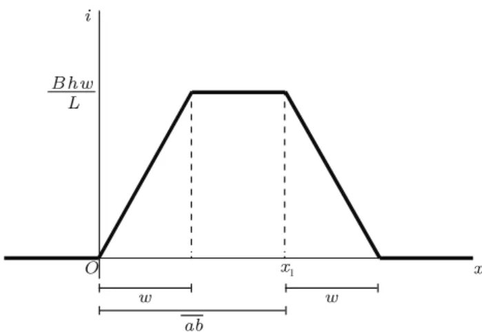
After the moment in which the loop is totally in-serted into the regionabcd, the magnetic flux over the area of the loop is constant and therefore the induced emf vanishes. However, because the electrical resistance is zero, the electric current remains unchanged. On the other hand, when the loop starts to leave the region, the magnetic flux starts to decrease, and it is easy to show that the current linearly decreases, vanishing when the loop leaves completely the abcd region. The current along the whole transit of a perfectly conducting loop through theabcdregion is shown in Fig. 3, as a function of the position of the leading side of the loop.
O x
i
x 1
w w
ab B h w
L
Figure 3 - Induced current as a function of the position of the leading side of the moving loop, in the case of a purely inductive loop.
Figures 2 and 3 are noticeably different. Part of the difference which is visually noticeable is related to the inversion of the sense of current propagation which hap-pens in the case of the purely resistive loop, depicted in Fig. 2. Due to the inversion in the sense of the current, the resistive force is opposite to the loop velocity, both in the entrance and in the exit of the regionabcd. The external agent makes positive work in both phases of the motion, and the total work done is equal to the en-ergy dissipated by Joule effect, as seen in Eqs. (4) and (5). In the purely inductive case, on the other hand, the magnetic force is opposite to the velocity when the loop is entering the region and in the same sense as the velocity when the loop is leaving the region. The external agent makes positive work when the loop is en-tering the region, in the same amount as the increase in the magnetic energy, as demonstrated by Eqs. (12) and (13), and makes negative work when the loop is leaving the region, in the same amount as the decrease in the magnetic energy. The total work made by the external agent is null, and the energy conservation principle is not violated.
2.2. Transition between the resistive and the perfectly conducting cases
time constant τ =L/R, is exactly the same that hap-pens in the case of a perfectly conducting loop, whose behavior is described by Eq. (9), and is represented by the dashed straight line passing through the origin. It is seen that, when the electric resistance tends to zero, the current simply tends to grow continuously, without divergence, while the flux due to the external magnetic field is increasing over the loop area.
B h v R1
10
B h v R1
5
B h v R1
2
B h v R1
i
O τ
1 2τ1 5τ1 10τ1
L R1 τ1=
R1/10
R1/5
R1/2
R1
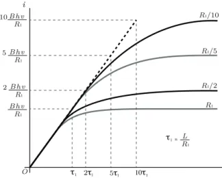
Figure 4 - Intensity of the induced current as a function of time after the entrance in the region of uniform magnetic field, for four loops with the same self-inductance and different values of the resistance.
In fact, it is easy to verify that the limit of Eq. (6) forR→0 is Eq. (9). Using Eq. (6) and expanding the exponential function in powers of the non-dimensional quantity (Rt/L), we obtain
i(t) =Bhv
(
t L −R
t2
L2 +. . . )
→ BhvL t , (14)
where the last result is obtained in the limit R→0. Moreover, for finiteR, the first order approximation shows that the current is proportional totfor small val-ues oft. That is exactly what is seen in Fig. 4. For any value of R, the initial rate of current variation is the same as the rate of variation for the case of perfectly conducting loop, given by Eq. (9).
On the other hand, for finite R and for t → ∞, Eq. (6) predicts that the limiting value of the current is inversely proportional toR, as in Eq. (2), since
lim
t→∞e
−Rt/L
= 0. (15)
The curves depicted in Fig. 4 confirm that the limit-ing value of the current increases for decreaslimit-ing electri-cal resistance. The time for attaining the limiting value of the current also increases for decreasing resistance, because the time constant is proportional toR−1.
Figure 4 also highlights an important property re-lated to the time constant τ, namely, that att=τ the current attains nearly 63% of its maximum value, which would be attained at such a time for linear growth.
3.
Perfectly conducting loop moving
exclusively under the effect of a
mag-netic field
In this section we discuss a situation which has a fun-damental difference relative to the cases discussed in the previous section. Here we consider a perfectly con-ducting moving loop which does not suffer the action of external forces. Only magnetic forces are in action when the loop enters or leaves theabcd region. From an energetic point of view the kinetic energy of the loop decreases when the loop enters the region, due to the magnetic force opposed to the sense of motion, and oc-curs a corresponding increase in magnetic energy. Since there is no dissipation in a perfect conductor, and since electromagnetic radiation is assumed to be negligible, the summation of kinetic energy Ec and magnetic
en-ergyEB is a constant,
Ec+EB=
1 2mv
2+1
2Li
2= 1
2mv
2
0, (16)
wherev0 is the initial speed of the loop.
From Eq. (8), assumingv=v(t),
Ldi
dt =Bhv(t), i(0) = 0. (17)
Remembering that v(t) =dx/dt, Eq. (17) can be written as follows
di= Bh
L dx , i(x= 0) = 0, (18)
whose solution is given by
i= Bh
L x . (19)
This result is exactly the same as obtained in Eq. (10). It is therefore demonstrated that, even for variable loop velocity due to the effect of the magnetic force, the intensity of the induced current grows linearly with the distance of penetration of the leading front of the loop into theabcdregion.
If the loop velocity vanishes before the loop is com-pletely inside theabcdregion, the magnetic force sends the loop moving back, reflecting it from the region with the magnetic field, so that the loop recovers the initial kinetic energy, but moving in opposite sense. For that to occur, the length of the segment along the motion must be larger than the distance of maximal penetra-tion in the regionabcd, namelyw > X, whereX is the point where the kinetic energy vanishes,
1 2mv
2 0=
1 2Li
2(X). (20)
Using Eq. (19), condition (20) be put in the follow-ing form,
1 2mv
2 0=
1 2L
(
BhX L
)2
which leads to the following expression for the distance of maximum penetration into theabcdregion,
X =
√ mL
Bh v0. (22)
Consequently, the condition for occurrence of reflec-tion from theabcdregion is as follows,
w > √
mL
Bh v0. (23)
If condition (23) is not satisfied, the loop enters com-pletely in the abcd region, despite the breaking mag-netic force. Therefore, it emerges in the opposite side. When leaving the region, the magnetic force is in the same sense as the motion, and the current decreases and finally vanishes, when the loop has recovered the initial velocity.
The conclusion is that, due to the absence of dissipa-tion in the perfectly conducting loop, the loop recovers the initial kinetic energy, no matter if it suffers reflec-tion from the abcdregion or if it crosses through that region. Similar result was found in the analysis of the motion of a magnet passing through a superconducting tube [5].
4.
Some numerical results
For further comparison between the cases of purely re-sistive and purely inductive loops moving with con-stant velocity under the influence of an external agent, we produce some numerical estimates, considering two square loops with side h, made from a cylindrical wire with transverse radius r, with r < h. We assume
h = 5.0 cm and r = 1.0 mm. The magnitude of the magnetic field in the abcd region is assumed to be 0.05 T. For order of magnitude estimate we assume that the mass density of the wire is near that of cop-per, ρm≃8.9×10³ kg/m3, and that the resistivity of
the wire in the resistive case is nearly that of copper,
ρ≃1.7×10⁻⁸ Ω ·m.
The electric resistance of the resistive loop is given by
R=ρ4h
πr2, (24)
and the inductance of the square loops is given by [6]
L≃2µπ0h [
ln
(h
r
)
−0.774
]
, (25)
where µ0 is the magnetic permeability of the vacuum.
For the values of parameters which we have assumed,
R≃1.1×10⁻³ Ω andL≃1.3×10⁻⁷ H.
Assuming that the inductance can be neglected,i.e.,
assuming the validity of the resistive model, we use Eq. (2) and obtain the magnitude of the current in the purely resistive loop,
|iR|= Bvπr
2
4ρ . (26)
On the other hand, the maximum magnitude of the current in the purely inductive loop can be obtained from Eq. (9),
|iL|max.= Bπh
2µ0[ln (h/r)−0.774]
, (27)
where Eq. (25) has been used for the inductance of the loop.
The ratio between the current intensities in the two limiting cases, obtained from Eq. (27) divided by Eq. (26), is therefore
|iL|max.
|iR|
= 2ρh
µ0vr2[ln (h/r)−0.774]≃
416
v . (28)
Considering the loop speedv≃1.0 m/s, this rough estimate shows that the maximum value of the current in the perfectly conducting loop is nearly 400 times the intensity of the current in the purely resistive loop. The current intensities in the perfectly conducting and in the resistive loop, Eqs. (27) and (26), would be re-spectively≃1000 A and≃2.3 A. This simple example shows that the perfectly conducting loop with inductive properties, despite avoiding the divergences predicted when the inductance is neglected, may indeed feature currents which are much more intense than the current in a resistive loop with the same geometry.
We also make numerical estimates of the conditions for which it is reasonable to neglect the effects of self-inductance for a moving loop of wire, considering typi-cal parameters. As discussed in the paragraph following Eq. (7), the inductive effects can be neglected in the case of a resistive loop if the time constantτ=L/Ris very small compared with a typical time interval. For the parameters which we have assumed for the resistive loop, τ ≃ 1.2×10⁻⁴ s. As a relevant time scale it is
possible to use the time for the loop to enter or to leave the abcdregion, given by h/v. The condition for rele-vance of self-inductance effects, therefore, can be cast as follows
v≥ 5.0×10 −2
1.2×10⁻⁴ ≃416
m
s . (29) In the case of loop speed v = 1 m/s, as assumed in the previous paragraph, self-inductive effects can be neglected for resistive loops. Even for v = 10 or 20 m/s, relatively high values for laboratory demon-stration, self-inductive effects can be safely neglected.
Finally, we discuss on the conditions which deter-mine whether a perfectly conducting loop of wire mov-ing without the influence of an external agent is re-flected or enters completely into the regionabcd. Solv-ing Eq. (23) for v0, remembering that we are
consid-ering w=h, we obtain that the loop is reflected if the initial velocity satisfies the condition
v0<
Bh2
√
mL. (30)
5.
Final remarks
In the present work we have used basic concepts of electromagnetic theory to discuss what happens with a perfectly conducting loop of wire moving through a re-gion with a uniform and stationary magnetic field. The study was motivated by the observation that even well-known textbooks may convey the notion that induced currents do no appear in such loops, since the appear-ing of a current would violate the principle of energy conservation [1]. Using a mathematical approach con-sistent with that of textbooks on general physics, we have tried to show that such reasoning is not correct, being a consequence of neglecting the self-inductance of the loop, which can not be neglected when the electric resistance is negligible.
In the discussion of the problem we have considered the case of a loop with resistive and inductive proper-ties moving with constant velocity, with emphasis on the limiting cases of purely resistive and purely induc-tive loop, and also the case of a loop moving without influence of a external agent. In the latter case, the velocity of the loop varies due to the interaction with the magnetic field. The theoretical analysis has been illustrated by some numerical estimates.
Our analysis has used a particular physical situation to emphasize the general feature that conclusions which are spurious and incompatible with observations can be obtained from theoretical analysis, if limited modeling is utilized for description of situations which are beyond the range of validity of a model, and that more accurate modeling can put the analysis back in consonance with observations. Other similar situations can be found in different physical contexts. For instance, some analogy can be found with a mechanical situation, related to the inertia of a body. The current does not diverge in a perfectly conducting loop of wire under the effect of an induced eletromotive force, due to the self-inductance, in the same way as the velocity of a body does not
change instantly under the effect of a force, due to the body inertia.
The bottom-line is that the phenomena which have been discussed offer excellent opportunity for discussion of basic features of electromagnetic theory, and also op-portunity for discussions on the limitations of models which are utilized for description of physical systems. A model will always be a simplified representation of re-ality, so that the results obtained with use of the model are valid only within a limited context [7–9].
Acknowledgments
L.F.Z. acknowledge support from Brazilian agency CNPq. The authors are grateful to Dr. P. Pureur Neto for motivating discussions and useful suggestions.
References
[1] P.A. Tipler and G. Mosca,Physics for Scientists and
Engineers: Extended Version(E.H. Freeman and Co.,
New York, 2004), 5th ed..
[2] R.W. Chabay and B.A. Sherwood, Matter and Inter-actions: Volume 2: Electric and Magnetic Interactions (John Wiley, 2010), 3rd. ed.
[3] W.M. Saslow, American Journal of Physics 55, 986 (1987).
[4] O.F. Schilling and S.S. Sugui Jr., European Journal of Physics25, 337 (2004).
[5] Y. Levin and F.B. Rizzato, Physical Review E 74, 066605 (2006).
[6] http://emclab.mst.edu/inductance/square.html
[7] R.S. Justi and J.K. Gilbert, International Journal of Science Education24, 369 (2002).
[8] M. Develaki, Science and Education16, 725 (2007).