Modeling and Design of Five Level Cascaded H-Bridge Multilevel
Inverter with DC/DC Boost Converter
Vinayaka B.C
1,
S. Nagendra Prasad
2 1M.Tech Student Scholar, 2Associate professor, Department of EEE, The National institute of Engineering Mysore, Karnataka India
Abstract
Power electronic converters, especially DC/AC Sinusoidal Pulse Width Modulation inverters have been extending their range of use in industry because of their numerous advantages. They typically synthesize the stair –case voltage waveform (from several dc sources) which has reduced harmonic content. This paper aims to extend the knowledge about the performance of Five level Cascaded H-Bridge MLI topology with DC/DC Boost Converter using SPWM for fixed DC Source. The output voltage is the sum of the voltage that is generated by each bridge. The switching angles can be chosen in such a way that the total harmonic distortion is minimized. This topology incorporates Boost Converter in the input side which magnifies the fundamental output voltage with reduction in total harmonic distortion. It also incorporates LC filter and hence output is drawn near the sine wave because of more levels. Results of experiments proved efficiency of 95%.The performance of the proposed SPWM strategy in terms of output voltage and THD has studied successfully and shown using MATLAB/Simulink.
Keywords
- Multi level Inverter (MLI), Sinusoidal Pulse Width Modulation (SPWM), insulated-gate bipolar transistor (IGBT), Cascaded H-Bridge (CHB)I.
Introduction
Power Electronics is the art of converting electrical energy from one form to another in an efficient, clean, compact, and robust manner for convenient utilization. It has found an important place in modern technology being core of power and energy control. It is the technology associated with efficient conversion, control and conditioning of electric power from its available input into the desired output form. Power electronics and converters utilizing them made a head start when the first device the Silicon Controlled Rectifier was proposed by Bell Labs and commercially produced by General Electric in the earlier fifties.
The simplest dc voltage source for a VSI may be a battery bank, which may consist of several cells in series-parallel combination. Solar photovoltaic cells can be another dc voltage source. A voltage source is called stiff, if the source voltage magnitude does not depend on load connected to it. All voltage source inverters assume stiff voltage supply at the input.
The first topology introduced was the series H-bridge design [1]. This was followed by the diode clamped converter which utilized a bank of series capacitors. A later invention detailed the flying capacitor design in which the capacitors were floating rather than series-connected. Another multilevel design involves parallel connection of inverter phases through inter-phase reactors. Several combinational designs have also emerged some involving cascading the fundamental topologies [3-6].
These designs can create higher power quality for a given number of semiconductor devices than the fundamental topologies alone due to a multiplying effect of the number of levels.
Recent advances in power electronics have made the multilevel concept practical [1-6]. In fact, the concept is so advantageous that several major drives manufacturers have obtained recent patents on multilevel power converters and associated switching techniques. It is evident that the multilevel concept will be a prominent choice for power electronic systems in future years. Moreover, abundant modulation techniques and control paradigms have been developed for multilevel converters such as sinusoidal pulse width modulation (SPWM), selective harmonic elimination (SHE-PWM), space vector modulation (SVM), and others. In addition, many multilevel converter applications focus on industrial medium-voltage motor drives [7], utility interface for renewable energy systems [8], Universal Power Conditioner [9] and traction drive systems [10].
II.
STUDY OF CASCADED H BRIDGE
MULTILEVEL INVERTER
For a medium voltage grid, it is troublesome to connect only one power semiconductor switch directly. As a result, a multilevel power converter structure has been introduced as an alternative in high power and medium voltage situations. A multilevel converter not only achieves high power ratings, but also enables the use of renewable energy sources. Renewable energy sources such as photovoltaic, wind, and fuel cells can be easily interfaced to a multilevel converter system for a high power application [1-3].
The concept of multilevel converters has been introduced since 1975. The term multilevel began with the three-level converter. Subsequently, several multilevel converter topologies have been developed [6-13]. However, the elementary concept of a multilevel converter to achieve higher power is to use a series of power semiconductor switches with several lower voltage dc sources to perform the power conversion by synthesizing a staircase voltage waveform.
The attractive features of a multilevel converter can be briefly summarized as follows.
Staircase waveform quality: Multilevel converters not only can generate the output voltages with very low distortion, but also can reduce the dv/dt stresses.
Input current: Multilevel converters can draw input current with low distortion.
Switching frequency: They can operate at both fundamental switching frequency and high switching frequency PWM.
III.
FIVE LEVEL CASCADED
H-BRIDGE MLI STRUCTURE
Conventional cascaded multilevel inverters are one of the most important topologies in the family of multilevel and multi-pulse inverters. The cascade topology allows the use of several levels of DC voltages to synthesize a desired AC voltage. The DC levels are considered to be identical since all of them are fuel cells or photovoltaics, batteries, etc. [20]. It requires least number of components compared to diode-clamped and flying capacitors type multilevel inverters and no specially designed transformer is needed as compared to multi pulse inverter.
Since this topology consist of series power conversion cells, the voltage and power level may be easily scaled. The concept of this inverter is based on connecting H-bridge inverters in series to get a sinusoidal voltage output. The output voltage is the sum of the voltage that is generated by each cell. The number of output voltage levels are 2n+1, where n is the number of cells. The switching angles can be chosen in such a way that the total harmonic distortion is minimized. An n level cascaded H-bridge multilevel inverter needs 2(n-1) switching
devices where n is the number of the output voltage level.
Fig.1 Five level CHB inverter
Cascade topology proposed in [21] uses multiple dc levels, which instead of being identical in value are multiples of each other. It also uses a combination of fundamental frequency switching for some of the levels and PWM switching for part of the levels to achieve the output voltage waveform. This approach enables a wider diversity of output voltage magnitudes; however, it also results in unequal voltage and current ratings for each of the levels and loses the advantage of being able to use identical, modular units for each level.
IV.
THE PROPOSED MULTILEVEL
INVERTER
The single phase cascaded five level inverter topology [22] has been proposed in Fig.1 .The circuit consists of eight main switches in two series connected H-bridge configuration S1~S4, and S5~S8. The number of dc sources are two so the output voltage of the cascaded multilevel inverter is Vo= V1+V2. The output waveforms of multilevel inverters are in a stepped waveform therefore they have reduced harmonics compared to a square wave inverter.
Each separate dc source (SDCS) is connected to a single-phase full-bridge, or H-bridge inverter. Each inverter level can generate three different voltage outputs, +Vdc, 0, and –Vdc by connecting the dc source to the ac output by different combinations of the four switches, S1, S2, S3, and S4. To obtain +Vdc, switches S1 and S2 are turned on, whereas –Vdc can be obtained by turning on switches S
3 and S4. By turning
on S1 and S2 or S3 and S4, the output voltage is 0. Similarly S5 and S6 for +Vdc, switches S7 and S8are turned on for –V
dc. The ac outputs of each of the
series such that the synthesized voltage waveform is the sum of the inverter outputs. As given below
Switches Turn On Voltage Level
S1, S2 +Vdc
S1,S2,S5, S6 +2Vdc
S4,D2,S8,D6 0
S3,S4 -Vdc
S3,S4,S7,S8 -2Vdc
Table 1 the switching states of Five Level CHB
A single-phase structure of a five level cascaded inverter with DC/DC boost converter is illustrated in Figure 3. The operation of this topology is as same as conventional 5-level CHB, difference lies in the voltage level which is due to presence of DC/DC boost converter which boosts the input voltage the designed value.
Fig.2 Five-level CHB MLI with DC/DC Boost Converter
V.
DESIGN OF PROPOSED
TOPLOGY
5.1 DC/DC BOOST CONVERTER
Boost converter steps up the input voltage magnitude to a required output voltage magnitude without the use of a transformer [23]. The main components of a boost converter are an inductor, a diode and a high frequency switch as shown in fig 3.3.1[24]. These in a coordinated manner supply power to the load at a voltage greater than the input voltage magnitude.
Fig.3 Boost Converter power stage
Inductor Selection
Often data sheets give a range of recommended inductor values. If this is the case, it is recommended to choose an inductor from this range. The higher the inductor value, the higher is the maximum output current because of the reduced ripple current. The lower the inductor value, the smaller is the solution size.
The following equation [36] is a good estimation for the right inductor:
……… (1)
Rectifier Diode Selection
To reduce losses, Schottky diodes should be used. The forward current rating needed is equal to the maximum output current.
IF = IOUT(max) ...(2)
IF = average forward current of the rectifier diode
IOUT(max) = maximum output current necessary in the
application
Output Capacitor Selection
Best practice is to use low ESR capacitors to minimize the ripple on the output voltage. Ceramic capacitors are a good choice.
…... (3) Po= output power; Cb= input capacitor
For a good practice choose Cf= 5% of Cb
Here input voltage is 12+12=24V. Due to the presence of DC/DC boost Converter voltage will increase to 48+48=96V.
5.2 Measured Parameters
1. Input voltage 24V
2. Output voltage 95V
3. Input current 8.3A
4. Output current 2A
5. Input power 24*8.33 = 200W
6. Output power 95*2=190W
=95 %
5.3 Firing pulse analysis
SPWM or sinusoidal pulse width modulation is widely used in power electronics to digitize the power so that a sequence of voltage pulses can be generated by the on and off of the power switches. The pulse width modulation inverter has been the main choice in power electronic for decades, because of its circuit simplicity and rugged control scheme SPWM switching technique is commonly used in industrial applications SPWM techniques are characterized by constant amplitude pulses with different duty cycle for each period. The width of this pulses are modulated to obtain inverter output voltage control and to reduce its harmonic content. Sinusoidal pulse width modulation or SPWM is the mostly used method in motor control and inverter application.
Specificataions:
Type; SPWM
Carrier frequency =3Khz Operetaing Frequency=50Hz, Gain=K=6500
Phase delay= 0,-pi/3
VI.
SIMULATION RESULTS
6.1 Modeling of CHB MLI
Fig.4 shows the Matlab/Simulink Model of five level Cascaded H-Bridge multilevel Inverter with DC/DC Boost Converter. Each H-bridge DC voltage is 12 V. Hence total input is 24volts
Fig.4 DC/DC Boosted Five level Inverter with Filter
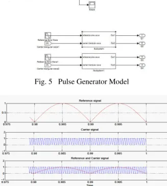
Fig.5 shows the Matlab/Simulink pulse generator model. The Switches are turned ON and turned OFF with a phase delay of 0 and –pi/3 respectively. Fig.6 shows Simulated Reference and Carrier Wave
Fig. 5 Pulse Generator Model
Fig.6 Simulated Reference and Carrier Wave
Fig.7 shows the Matlab/Simulink model Boosted 5-level CHB MLI output voltage without filter, having Magnitude of 96V in staircase(stepped) AC, to get pure sine wave an LC filter is added which is shown in figure 8
Fig. 8 Basic Five level CHB MLI output voltage with DC/DC boost converter and filter
6.2 THD Analysis
Total harmonic distortion, or THD, is the summation of all harmonic components of the voltage or current waveform compared against the fundamental component of the voltage or current wave. THD calculations can be obtained from the SIMULINK. The switching pattern that is used in this project for all of the multilevel inverters is Sinusoidal PWM technique. In this method the switching angles for switches should be calculated in such a way that the dominant harmonics are eliminated (minimized). For a 5-level inverter the 5th harmonic will be eliminated.
Where, V1= Fundamental Voltage magnitude
V2 = Magnitude of 2nd Harmonic
V3 = Magnitude of 3rd Harmonic
. Vn = Magnitude of n
th
Harmonic
The formula above shows the calculation for THD on a voltage signal. The end result is a percentage comparing the harmonic components to the fundamental component of a signal. The higher the percentage, the more distortion that is present on the mains signal.
Fig.9 %THD of DC/DC Boosted Five level Inverter with filter
VII.
CONCLUSION
It has been observed from the simulation results that the overall efficiency of the developed five level inverter is 95% which is more than the conventional DC to AC inverter. The two-level inverter has the lowest cost and weight in comparison with the other topologies. But it has very high THD and it is not practical to have an output voltage with high such THD. The design of the 5-level multilevel inverters seems to be better than the 9-level multilevel inverters. By increasing the number of levels, the cost and weight of the multilevel inverter will be increased. So this topology is well suited for industrial drives.
REFERENCES
[1]. R.H. Baker, Electric Power Converter, U.S. Patent Number 3,867,643, February 1975. [2]. R.H. Baker, High-Voltage Converter
Circuit, U.S. Patent Number 4,203,151, May 1980.
[3]. Kelaiaia Mounia Samira, Labar Hocine,
Bounaya Kamel, and Kelaiaia Samia “Effect of Flaying Capacitors on Improving the 4 Level Three-Cell Inverter” World Academy of Science, Engineering and Technology 30 2009.
[4]. Javier Pereda, Student Member, IEEE, and Juan Dixon, Senior Member, IEEE “High Frequency Link: A Solution for Using Only One DC Source in Asymmetric Cascaded Multilevel Inverters” IEEE TRANSACTIONS ON INDUSTRIAL ELECTRONICS, VOL. 58, NO. 9, SEPTEMBER 2011
[5]. Yushan Liu, Student Member, IEEE, Baoming Ge, Member, IEEE, Haitham Abu-Rub, Senior Member, IEEE, and Fang Zheng Peng, Fellow, IEEE “An Effective Control Method for Three-Phase Quasi-Z-Source Cascaded Multilevel Inverter Based Grid-Tie Photovoltaic Power System” IEEE TRANSACTIONS ON INDUSTRIAL ELECTRONICS
[6]. Xiaomin Kou, Student Member, IEEE, Keith A. Corzine, Member, IEEE, and Yakov L. Familiant, Student Member, IEEE
[7]. Maria Imecs, Andrzej M. Trzynadlowski, Fellow, IEEE, Ioan I. Incze, and Csaba
Szabo “Vector Control Schemes for Tandem-Converter Fed Induction Motor Drives” IEEE TRANSACTIONS ON POWER ELECTRONICS, VOL. 20, NO. 2, MARCH 2005
[8]. Madhav D. Manjrekar Thomas A. Lipo A hybrid multilevel inverter topology for drive applications
[9]. Leon M. Tolbert, Senior Member, IEEE, Fang Zheng Peng, Senior Member, IEEE, and Thomas G. Habetler, Senior Member,
IEEE “A Multilevel Converter-Based Universal Power Conditioner” IEEE TRANSACTIONS ON INDUSTRY APPLICATIONS, VOL. 36, NO. 2, MARCH/APRIL 2000
[10]. Leon M. Tolbert, Senior Member, IEEE, Fang Zheng Peng, Senior Member, IEEE and Thomas G. Habetler, Senior Member,
IEEE “Multilevel Converters for Large Electric Drives” IEEE TRANSACTIONS ON INDUSTRY APPLICATIONS, VOL. 35, NO. 1, JANUARY/FEBRUARY 1999
[11]. M.S.Sivagamasundari, 1 P.Melba Mary2 “A Single Phase Eleven Level Cascaded H-Bridge Multilevel Inverter for Photovoltaic Systems Using Multicarrier Pwm” International Journal of Modern Engineering Research (IJMER) www.ijmer.com Vol.2, Issue.6, Nov-Dec. 2012 pp-4703-4709 ISSN: 2249-6645 [12]. M.S.Sivagamasundari1, Dr.P.Melba Mary2
“Analysis of Cascaded Five Level Multilevel InverterUsingHybrid PulseWidth Modulation” International Journal of Emerging Technology and Advanced Engineering ISSN 2250-2459, ISO 9001:2008 Certified Journal, Volume 3, Issue 4, April 2013
[13]. Mahrous Ahmed, Ibrahim Taha, Sherif Ghoneim “Multilevel Inverter with Natural Balancing of DC Sources for PV System Applications” / International Journal of Engineering Research and Applications (IJERA) ISSN: 2248-9622 www.ijera.com Vol. 3, Issue 1, January -February 2013 [14]. Thierry A. Meynard, Member, IEEE, Henri
Foch, Philippe Thomas, Jacques Courault, Roland Jakob, and Manfred Nahrstaedt
“Multicell Converters: Basic Concepts and Industry Applications” IEEE TRANSACTIONS ON INDUSTRIAL ELECTRONICS, VOL. 49, NO. 5, OCTOBER 2002
[15]. P. Satheesh Kumar, Dr. S. P. Natarajan, Dr. Alamelu Nachiappan , Dr. B. Shanthi
“Performance Evaluation of Nine Level Modified CHB Multilevel Inverter for Various PWM Strategies” International Journal of Modern Engineering Research (IJMER) Vol. 3, Issue. 5, Sep - Oct. 2013 pp-2758-2766 ISSN: 2249-6645
[16]. F. Khoucha, A. Ales, A. Khoudiri, K. Marouani, M.E.H. Benbouzid and A.
Kheloui “ A 7-Level Single DC Source Cascaded H-Bridge Multilevel Inverters Control Using Hybrid Modulation” XIX International Conference on Electrical Machines - ICEM 2010, Rome
[17]. A. Nabae, I. Takahashi, and H. Akagi, "A New Neutral-Point Clamped PWM Inverter," Proceedings of the Industry Applications Society Conference, pages 761-766, September/October 1980.
[18]. Xiaoming Yuan, Member, IEEE, and Ivo Barbi, Senior Member, IEEE
“Fundamentals of a New Diode Clamping Multilevel Inverter” IEEE TRANSACTIONS ON POWER ELECTRONICS, VOL. 15, NO. 4, JULY 2000
[19]. T.A. Meynard, H. Foch, "Multi-level Conversion: High Voltage Choppers and Voltage-source Inverters," Proceedings of the IEEE Power Electronics Specialist Conference, pages 397-403, 1992
[20]. F. Z. Peng, J. S. Lai, J. W. McKeever, J.
VanCoevering, “A Multilevel Voltage-Source Inverter with Separate DC Voltage-Sources for Static Var Generation,” IEEE Transactions on Industry Applications, vol. 32, no. 5, Sept. 1996, pp. 1130-1138. [21]. M. D. Manjrekar, T. A. Lipo, “A
Generalized Structure of Multilevel Power Converter,” IEEE Conference on Power Electronics, Drives, and Energy Systems, Australia, 1998, pp. 62-67.
[22]. Mr. G. Venkateswarlu, Dr.Psangameswar Raju P.GIRIPRASAD SINGH Analasis Of Photovoltaic Cell An Application Of A Level Shifted Cascaded Multilevel Inverter International Journal of Engineering Research & Technology (IJERT) Vol. 1 Issue 7, September – 2012
[23] R. Arulmurugan, N. Suthanthira Vanitha