Electronics Based VPGM Controller
Board
Tiago José Ferreira Mendonça
F
ORJ
URYE
VALUATIONMestrado Integrado em Engenharia Eletrotécnica e de Computadores Advisor: Prof. Hélio Mendes de Sousa Mendonça
Co-Advisor: Prof. António Paulo Gomes Mendes Moreira
O CERN centra a sua atividade na realização de pesquisas nucleares visando descobrir os alicerces que sustentam o Universo. Tais experiências decorrem em regime controlado com recurso a acel-eradores de partículas. Um dos módulos fulcrais para o sucesso das mesmas é o sistema de vácuo. Este é assegurado por diversos equipamentos, incluindo bombas e válvulas, que são controlados por um PLC. Porém, apesar da sua fiabilidade, robustez e longevidade, uma arquitetura de con-trolo desta natureza acarreta alguns inconvenientes, tais como perda de suporte, dificuldade de integração com novos modelos e um considerável custo de aquisição.
Nesta dissertação é explorada a viabilidade e fiabilidade de substituir um PLC por uma ar-quitetura sustentada em SBC, nomeadamente a versão mais recente da BeagleBone. Esta unidade é usada como módulo de processamento, sendo a acquisição física dos sinais do grupo de vácuo feita através de uma placa protótipo concebida especificamente para o propósito. A interface entre esta e a unidade de processamento é feita por comunicação série, nomeadamente SPI. A arquitetura de controlo assenta num soft-PLC, CODESYS, e está de acordo com a norma IEC 61131. Um fator digno de destaque neste projeto prende-se com a utilização de princípios de memória partilhada para transmissão de informação entre o CODESYS e o programa inerente à configuração do protocolo SPI. O desempenho do sistema é testado tanto a nível funcional como temporal, comprovando-se a adequabilidade à sua aplicação final. Embora o projeto seja desen-volvido para um propósito específico, é aferida a viabilidade para que uma arquitetura desta na-tureza seja extrapolada para outros contextos de automação industrial, sendo também ponderada a eventual utilização de um microcontrolador em detrimento de uma SBC. Finalmente, são também desenvolvidos testes de comunicação com um escravo Profibus, de forma a corroborar o correto funcionamento de uma pilha protocolar oriunda de um projeto prévio e abrindo o horizonte para uma futura integração com o sistema.
CERN centers its activity on nuclear research aiming to discover the building blocks in which relies the universe. Such experiments occur on a controlled environment taking advantage of particles accelerators. Pumping system is one of most important modules to its operation. This relies on several devices, including valves and pumps, that are controlled by a PLC. Despite its reliability, robustness and long term operation, this kind of architecture implies some drawbacks, like loss of support, difficult integration with new models and high acquisition cost.
On this thesis it is explored the feasibility and reliability of replacing a PLC by a SBC-based architecture, namely the newer model of BeagleBone. This element is used as processing unit, being the physical acquisition of vacuum group signals performed by a prototype board design from scratch. The interface with core unit relies on serial communication, namely SPI protocol. The control architecture is developed on a soft-PLC, CODESYS, and is compliant with IEC 61131 standard. One remarkable feature of this project is that the data exchange between control pro-gram (running on CODESYS) and SPI interface script is made according with shared memory principles. System’s performance is evaluated on functional and temporal points of view, being confirmed that fits system requirements. Although the project is adjusted for a single application, the final results support the possibility of extrapolating it for different industrial automation scenar-ios, being also performed a comparation with a system based on a microcontroller. Additionally, it is also showed some communication tests with a Profibus slave based on an open-source stack developed on a previous project, being check its correct operation and preparing future integration with the system.
In first place, I want to thank to professors Hélio Mendonça and António Paulo Moreira for the support, helpfulness, recommendations and the knowledge transmitted during all thesis stages. I also thank the financial support provided by INESC TEC during the internship at CERN. Still on INESC crowd, a special acknowledgment to José Carlos Azevedo for all the effort invested on project hardware development.
I would like to say also thank you to Rodrigo Ferreira for taking care of me during my swiss adventure, for pushing me to go further even when everything was burnt, literally, and, not only for the technical, but also personal advices that keep me on the right track. Also, an honorable mention to remaining Bâtiment 30 group for the hospitality and easy integration.
Lastly, but not least, I thank to my parents and brother for carrying me when I still was an open-loop system and for always providing the rights inputs and outputs that allow to tune my personal controller. I hope that the resulting impulse response makes them proud. And, of course, for being the second family, I appreciate friends company, namely the ones that always forced me to abandon my computer screen at Friday’s nights and to go out from engineering ecosystem.
Tiago Mendonça
Gary Marcus
1 Introduction 1
1.1 Problem statement, goals and motivation . . . 1
1.1.1 Project details and objectives . . . 2
1.2 Document structure . . . 3
2 State of the art 5 2.1 Particles accelerators . . . 5
2.1.1 Basic principles . . . 5
2.1.2 CERN accelerator complex . . . 7
2.2 Vacuum system . . . 8
2.2.1 Vacuum principles and instrumentation . . . 8
2.2.2 CERN pumping groups . . . 11
2.2.3 VPGM control . . . 13
2.3 Programmable logic controller (PLC) . . . 15
2.3.1 PLC architecture . . . 15
2.3.2 IEC 61131 . . . 16
2.3.3 Input module . . . 20
2.3.4 Output module . . . 21
2.3.5 Source and sink . . . 22
2.3.6 Communication module . . . 23 2.4 Soft-PLC . . . 28 2.5 Single-board computer (SBC) . . . 29 2.6 Conclusions . . . 31 3 Hardware Architecture 33 3.1 Hardware overview . . . 33 3.2 PCB modules design . . . 36 3.2.1 Digital inputs . . . 37 3.2.2 Analog inputs . . . 41 3.2.3 Digital outputs . . . 46 3.2.4 Power supply . . . 49 3.3 PCB considerations . . . 51 3.4 Serial interface . . . 55 3.5 Profibusinterface . . . 57
3.5.1 Profibusconnector driver . . . 59
3.6 Conclusions . . . 60
4 Software Architecture 63
4.1 Software overview . . . 63
4.2 Control process software . . . 65
4.2.1 VPGM process . . . 66
4.2.2 Human-machine interface . . . 81
4.3 SPI software . . . 90
4.3.1 Serializerserial interface . . . 90
4.3.2 Thermocoupleserial interface . . . 91
4.3.3 ADS serial interface . . . 92
4.3.4 Output driver serial interface . . . 94
4.3.5 Implemented Script . . . 95
4.4 Scripts communication . . . 96
4.5 Profibusstack . . . 98
4.6 Conclusions . . . 100
5 Tests and Results 101 5.1 Process operation . . . 101
5.2 Time constraints . . . 102
5.2.1 Kernel latency . . . 103
5.2.2 System time requirements . . . 104
5.3 Hardware robustness . . . 107
5.4 HMI . . . 110
5.5 Profibustests . . . 112
5.6 Conclusions . . . 114
6 Conclusions and future work 117 6.1 Conclusions . . . 117
6.2 Microcontroller vs SBC . . . 118
6.3 Future work . . . 119
A Real time systems 121 A.1 Systems classification . . . 121
A.2 System latency measurement . . . 122
B Shell script configuration 123
C Group I/O connections 125
D Group control process test 127
E PCB electric schematic 129
2.1 Cavities on the beam pipe [1]. . . 6
2.2 Magnetes arrangement to confine the particle beam [1]. . . 7
2.3 CERN accelerator complex [2]. . . 8
2.4 Pressure ranges classification [3]. . . 9
2.5 Useful range of standard pumps [4]. . . 10
2.6 Pressure gauges application [4]. . . 11
2.7 Basic structure of a turbo-molecular pumping group [5]. . . 12
2.8 Front and back view of a CERN mobile pumping group. . . 13
2.9 Operation modes of VPGM [5]. . . 14
2.10 Hardware architecture [5]. . . 15
2.11 PLC architecture [6]. . . 16
2.12 IEC 61131-3 programming languages [7]. . . 17
2.13 PLC software architecture [8]. . . 18
2.14 PLC scan cycle [9]. . . 20
2.15 PLC DC input [10]. . . 21
2.16 PLC output (adapted from [11]). . . 22
2.17 Input and output sourcing unit [10]. . . 23
2.18 Input and output sinking unit [10]. . . 23
2.19 SPI multiple slaves communication [12]. . . 25
2.20 Daisy chain configuration [12]. . . 25
2.21 Profibus protocol stack [13]. . . 26
2.22 Profibus character codification [14]. . . 27
2.23 Profibus DP slave state machine [14]. . . 27
3.1 BeagleBone Greenoverview [15]. . . 34
3.2 BeagleBoneLCD display cap [16]. . . 35
3.3 RS485-USB adapter. . . 35
3.4 Hardware architecture. . . 36
3.5 Serializerinput protection circuit (adapted from [17]). . . 39
3.6 Serializerinput isolation circuit. . . 40
3.7 ADS8665 pinout [18]. . . 41
3.8 ADS8665 acquisition circuit. . . 44
3.9 MAX31856 pinout [19]. . . 45
3.10 MAX31856 acquisition circuit. . . 46
3.11 VNI8200XP pinout [20]. . . 47
3.12 VNI8200XP configuration. . . 49
3.13 Power supply protection (adapted from [17]). . . 50
3.14 Power supply circuit. . . 51
3.15 PLC upper and side view with respective dimensions, in mm. . . 52
3.16 Analogical and digital grounds separation. . . 53
3.17 Wires connectors [21]. . . 53
3.18 LCD board. . . 54
3.19 PCB board. . . 55
3.20 Serial bus buffer configuration. . . 57
3.21 MAX485 internal configuration and typical application [22]. . . 58
3.22 Termination resistors and failsafe circuit (adapted from [23]). . . 59
4.1 Software architecture. . . 65 4.2 Valve FB. . . 68 4.3 Turbo-molecular pump FB. . . 69 4.4 Primary pump FB. . . 71 4.5 UPS FB. . . 71 4.6 Vacuum gauge FB. . . 72 4.7 Bake-out FB. . . 72
4.8 Group state machine [24]. . . 73
4.9 Transitions between modes [24]. . . 74
4.10 Devices condition on each step [24]. . . 75
4.11 Group errors hierarchy (adapted from [24]). . . 76
4.12 Execution cycle. . . 81
4.13 Synoptics graphical disposition. . . 83
4.14 Valves synoptic (label not included). . . 83
4.15 Valves command mode flags. . . 84
4.16 Primary pump synoptic on off state with error flag enabled (left) and turbo pump synoptic, when on nominal state (right). . . 84
4.17 Group state synoptic before and after an error occurrence. . . 85
4.18 Basic Mode frame. . . 86
4.19 Login frame. . . 86
4.20 Expert Mode frame. . . 87
4.21 Manual Control frame. . . 88
4.22 Settings frame. . . 89
4.23 Sequence of status bits in Serializer [17]. . . 90
4.24 Calculation of parity bits [20]. . . 95
4.25 Script operation logic . . . 96
4.26 Data transmission between programs over shared memory. . . 97
4.27 Profibus stack architecture (adapted from [25]). . . 98
5.1 Minimum system response. . . 106
5.2 Maximum system response. . . 106
5.3 System response time. . . 107
5.4 PCB enclosure box design. . . 110
5.5 Terminal block and screwed pluggable connector (adapted from [21]). . . 110
5.6 HMI display. . . 111
5.7 7” HDMI display [26]. . . 112
5.8 Modular Profibus slave user for tests. . . 112
2.1 Action qualifiers [27]. . . 19
2.2 SPI bus mode [28] . . . 24
2.3 BeagleBone Greenand Raspberry Pi 3 specs [15][29] . . . 30
3.1 Electrical characteristics of PLC input module [30] . . . 37
3.2 Electrical characteristics of serializer [17] . . . 37
3.3 Input filter configuration [17] . . . 38
3.4 PLC digital output module characteristics [30]. . . 46
3.5 VNI8200XP characteristics [20]. . . 47
4.1 Primary pump faults hierarchy . . . 70
4.2 Thermocoupleregisters configuration. . . 92
4.3 ADS8665 registers configuration. . . 93
4.4 Master-to-slave 16-bit frame [20]. . . 94
4.5 Slave-to-master 16-bit frame [20]. . . 94
5.1 System latency measures. . . 103
5.2 System latency measures with preemptive patch. . . 104
5.3 Process cycle time and jitter measures. . . 105
5.4 Devices tests checklist. . . 108
5.5 Master-to-slave 8-bit frame [20]. . . 108
5.6 Slave-to-master 8-bit frame [20]. . . 109
5.7 Minimum timeout required per baud rate. . . 114
A.1 BeagleBone system latency [31]. . . 121
C.1 Output commands to control group devices. . . 125
C.2 Input signals provided by group devices . . . 126
D.1 Control process checklist. . . 128
Abbreviations
ADC Analog-to-Digital Converter
ARM Advanced RISC Machine
ASIC Application Specific Integrated Circuit
CPU Central Processing Unit
DC Direct Current
DP Decentralized Peripherals
EMF Electromotive Force
FB Function Block
FBD Function Block Diagram
FDL Fieldbus Data Link
FMS Fieldbus Message Specification
GPIO General Purpose Input/Output
GSD General Station Description
HDMI High-Definition Multimedia Interface
HMI Human-Machine Interface
I2C Inter-Integrated Circuit
IC Integrated Circuit
IEC International Electrotechnical Commission
IL Instruction List
LCD Liquid Crystal Display
LHC Large Hadron Collider
MSB Most Significant Bit
OS Operating System
OSI Open System Interconnection
PA Process Automation
PC Personal Computer
PLC Programmable Logic Controller
PRU Programmable Real-time Unit
RAM Random Access Memory
ROM Read-Only Memory
SBC Single-Board Computer
SCADA Supervisory Control and Data Acquisition
SDN Send Data with No acknowledge
SFC Sequential Function Chart
SOC System On Chip
SPI Serial Peripheral Interface
SRD Send and Request Data with reply
ST Structured Text
TMP Turbo-Molecular Pump
UART Universal Asynchronous Receiver-Transmitter
UHV Ultra-High Vacuum
UPS Uninterruptible Power Supply
USB Universal Serial Bus
Introduction
The present chapter has the purpose to introduce the thesis "Electronics Based VPGM Controller
Board". Then, on a first stage,1.1, it is explained the context in which it is proposed, the imposed
goals and motivation. On 1.2, it is exposed the document frame, structuring each one of the
following chapters.
1.1
Problem statement, goals and motivation
At CERN, the European Organization for Nuclear Research, the particles’ experiments are charac-terized by the increase of beams’ speed on circulating chambers along large kilometers. In specific points of their path, the beams circulating in opposite directions are forced to collide and many particles and radiation are released. These products are registered by detectors and posteriorly analyzed. With these events, the scientists aim to go back in time and recreate the conditions that rule the space matter immediately after the Big Bang occurrence.
During their trajectory, particles describe a specific path and collide at specific points. There, to ensure the expected behavior, the beam pipe must be properly isolated from the outside and free of any suspended air molecule inside, since, if not verified, the beam would collide with undesired particles and diverge from its path. So, the chamber stays at very low-pressure state, called Ultra High Vacuum (UHV). This condition is result of successive pumping stages and the first one is assured by turbo-molecular pumping groups. Depending of particles accelerator, they can be fixed or mobile. In last case, the mobile pumping groups (VPGMs) are composed by a turbo-molecular pump, a primary pump, vacuum gauges and one or more valves. The combined operation of all these devices must be carefully controlled. The control procedure is implemented on a programmable logic controller (PLC) allocated on a crate fitted on the trolley. This kind of
core solution is reliable, safe and ready to use. However, as stated in [2], at long term, the use
of a PLC may be associated to some drawbacks. Due to the constant release of new models, an older one will lose, gradually, its support, on both hardware, with no availability of spares, and software sides, due to the no release of development platform updates and loses compatibility with new operating systems, and the problems already faced on the past will become again a reality. In
addition (and although partially justified by the features offered), a PLC is not the cheapest option and its dissemination along almost two hundred mobile pumping groups implies a significant investment.
To suppress such shortcomings, the evaluation of the reliability and feasibility of an electronic card, whose core unit is micro-controller (or similar technology) based, to replace PLC use is of particular interest.
1.1.1 Project details and objectives
Following the showed road implies the consideration of two major concerns: ensures electrical compatibility with all the devices that compose the pumping group and implements the control process that supports the group operation.
Regarding electrical specifications, distinct kinds of interfaces must be supported. The large part of connections is of discrete kind, 0-24V. They are associated to feedback signals, which indicates the current state or operation mode of the devices, such as, for example, valves and pumps, and control signals, actuation orders executed on the devices. There are also analogical input connections that shall be conditioned, namely 0-10V signals and a type-k thermocouple
connection. A full list of group connections is attached on C. Additionally, the card must be
designed to be properly fed by the available power supply, a 24V DC UPS.
Furthermore, a core architecture is required to implement the control process. This element must acquire input data, process the information and generate a suitable output response, according with the group operation scheme.
In addition, a HMI must be included to allow user monitor and interaction, ordering process changes, configuring its parameters and handling devices operation.
The combination of all topics explained represents the main objective of the project. However, this not fully replace the current PLC-based control system. Therefore, additional features are indicated below but their contemplation is optional.
The connections described are I/O based. However, some devices may be interfaced through Profibus. This type of communication provides a more complete diagnosis than the previous one. Here, the PLC acts as master and the field devices as slaves, but, on a separate Profibus network, it is integrated on Vacuum SCADA, acting as a slave and exchanging data with a central master PLC.
In short, the project objectives are summarized on next topics: • Mandatory
-> Design of an hardware architecture, including acquisition circuit and processing unit. -> Implementation of pumping group control process with additional interlocks, error flags and respective handling action and possibility of devices manual control.
-> Implementation of an HMI to user interaction, receiving user inputs and providing a complete group diagnosis.
• Additional
-> Profibus support:
Acting as a master, interacting with turbo-molecular pump controller and vacuum gauge.
Acting as a slave in order to be integrated on vacuum group SCADA.
1.2
Document structure
The present report is composed by six chapters. Firstly, on the current one, it is introduced the subject in study as well as the respective objectives, providing some guidelines for the technical
features aimed. On2, it is presented the state of the art, being explored the useful topics to posterior
steps of project development, namely the utility of pumping groups, the control process inherent
to it, hardware support and other relevant group features. On chapters 3and 4, both hardware
and software architectures, respectively, are detailed from bottom to top, referring specific design
details and the tools that support development stages. On chapter5, the tests and results developed
on the system to evaluate its performance are presented. Finally, on chapter6, all work developed
is analyzed, being enumerated the remarkable achievements and the tasks not so well succeed, being suggested further actions that might be done in the future. Additionally, it is also included
onA,B,CandDsome additional information and guidelines to help the user through software
State of the art
In this chapter are explored the concepts that may be relevant on project development, creating a basis knowledge that will support the posterior stages.
Thus, firstly, it is contextualized the particles accelerators operation, 2.1, and why it implies
the existence of vacuum groups, 2.2, how they should be handled to be efficient on their task,
leading to PLC application and what are the characteristics that it offers that make it so widely
used on automation environment, 2.3, being, then, compared, software,2.4, and hardware,2.5,
options, aiming to satisfy the same purposes.
2.1
Particles accelerators
The possibility of knowing the history of the Universe is a common wish shared among all hu-manity. “What we are made for?” or “Where we came?” are questions that easily across our mind. However, their answer is not immediate and can cause some confusion. To solve these issues ex-ists the particle physics. This area tries to understand the base laws that support the Nature and its elements through the study of fundamental particles of matter. Since they were born at the Big Bang, their structure preserves the timeline of the Universe and reflects its evolution. With this purpose in mind, the scientists drive their experiments to pursuit the recreation of the conditions that were present at the primordial explosion and identify the subatomic particles associated. This
is only possible due to particle accelerator, the 21st century time machine.
2.1.1 Basic principles
A particle accelerator is defined as “a device that provides forces on charged particles by some combination of electric and magnetic fields and brings the ions to high speed and kinetic energy”
[32]. In other words, it’s a machine that allows the gradual acceleration of electrical particles and,
consequently, to reach successive higher levels of energy along a specific path. When a desired state of energy is obtained, they are forced to collide and the results (small size particles and radiation) are collected to posterior analysis. The parameters of the accelerator, like size, type of trajectory and energy level, are correlated and dependent from the end application. Although
the most well-known usage is the research area, these principles are also widely disseminated in medicine practices, namely radiography and radiation therapy, and in technological equipment, as,
per example, old televisions and computers monitor based on cathode rays [33].
Usually, the accelerators are classified in two types. In linear accelerators, particles travel down on a long and straight track, colliding with a target, while, in circular models, travel around
a variable number of times in a circle until they collide with the target [32][34]. Nevertheless, in
general, all kinds of accelerators share the same operation principles.
In first place, it is mandatory a particles source. Commonly, the circulated elements are protons or electrons. These particles are present in any material. However, they only assume a single number on hydrogen nuclei. So, this is the gas selected to provide the particles. The principle of extraction depends the type of the accelerator, but, generally, implies the bombardment of the
gas with energetic electrons that results in the ionization of the atoms [33]. As consequence, it is
obtained a beam of particles that is injected in the circulation channel, designated beam pipe. Once in circulation, the particles must be gradually accelerated in order to achieve the high states of energy. This goal is accomplished due to the presence of electromagnetic fields along the trajectory. The beam is properly segmented in sectors denominated cavities. In each one exists a microwave generator. When a passing particle interacts with these waves, it is created an electric force that, depending of the orientation, may push the particle forward, increasing the speed, or difficult the movement. This process repeated along all beam length results in a cumulative arising of the particles energy. However, this only happens if the interaction between the beam and waves occurs at a specific timing (the moment when the electric force impulses the movement). For a precisely coordination, the particles are aggregated in bunches. The spacing between cavities and
circulating bunches is proportional to the wavelength [33][32][35].
Figure 2.1: Cavities on the beam pipe [1].
Additionally, to assure a uniform distribution of the energy and to avoid collisions with the vessel’s walls, the bunches must be kept focused and concentrated at the center. That’s why, these same walls are complemented with dipoles and quadrupoles. They generate a magnetic field that conditions the particles’ trajectory. The dipoles are responsible for the concentration of the beam while the quadrupoles assure that the particles remain at the center, especially in non-linear paths
[35]. Also, the intensity of the field must increase with the energy of the beam. So, due to the
Figure 2.2: Magnetes arrangement to confine the particle beam [1].
Finally, when the pretended state of energy is reached, the particles are forced to collide. In research area, to monitor and track properly all the process, this event occurs in specific points
called detectors [34]. Here, all the information obtained is recorded and analyzed. The collision
may happen with a fixed target or between bunches circulating in opposite directions.
An additional condition to the above procedure is that the all beam pipe must remain at vac-uum. This state is essential to avoid the collision of the particles with the molecules suspended in the air that would cause significant losses of energy and the deviation of the beam. These situa-tions unfeasible all the process. So, a pumping group is a mandatory system. The low pressure associated depends from the level of energy inherent to the accelerator.
2.1.2 CERN accelerator complex
At CERN, the particles experiences are developed by a complex of machines. These elements are connected in chain. So, the output beam of one accelerator constitutes the input of the next and so on. This configuration allows successive levels of higher energy that culminate at LHC. The previous elements are necessary to inject the particles into the chambers and to accelerate them properly to the next stages. The Large Hadron Collider is an accelerator that has two beams with bunches circulating in opposite directions along, approximately, 27 km in a circumference path. Along this length, there are four experiments, points where, after several passages, occur collisions
Figure 2.3: CERN accelerator complex [2].
The high stage of energy associated to the LHC depends substantially from both magnets cooling and vacuum systems. For one side, it is more challenging bend the particles trajectory to the beam pipe. Therefore, a higher excitation current at the magnets is needed. To avoid power dissipation, it is implemented a cryogenic system, based on superfluid helium, which allows the operation at temperatures as low as 1.9k. The thermal insulation with the surrounding area is only possible due to a vacuum barrier. Besides, the beam pipe must also be composed with the minimal concentration of gas in order to avoid undesirable collisions with residual particles. So,
the vacuum system plays a dual key role in the accelerator’s activity [34][35][2].
2.2
Vacuum system
As stated previously, the vacuum in beam pipe is an essential ingredient to a correct full opera-tion. If this condition isn’t verified, the beam particles interact with the residual gas present in circulating chambers. As result, they are scattered and diverge from the planning path and may also collide with chamber’s walls. Therefore, the lifetime of the beam is reduced as well as the luminosity produced, and the ionization occurred on the interaction induces instability in the
circu-lating beam [4]. In synthesis, the overall performance of the machine is compromised. This way,
the pressure at the chamber must remain at very low value to assure the efficient of the process.
2.2.1 Vacuum principles and instrumentation
Pressure is defined as the force applied per unit of surface inside a restricted space. In other words, when a gas is contained in a vessel, molecules describe thermal movements and interact with each
other and with the walls of the surface [3]. Consequently, this results in partial forces that are
applied over the particles and limit their behavior. The sum of all these forces determines the pressure inside the recipient. The S.I. unit is Pascal, Pa. However, it is also common to express in torr, bar or atm, whose reference, in last one, is the atmospheric pressure at sea-level, 101.325 Pa.
In literature, vacuum is described as “the state of a gas at which its pressure in a vessel and therefore its particle density is lower than that of the ambient surrounding atmosphere or in which the pressure of the gas is lower than 300 mbar, i.e. lower than the pressure of the atmosphere
on the Earth’s surface” [3]. It is possible to identify distinct levels of vacuum according with the
pressure range considered.
Figure 2.4: Pressure ranges classification [3].
In particles accelerators, vacuum chamber is at ultra-high vacuum. To achieve and maintain this condition, it is mandatory a special vacuum system capable of generating this kind of pressure. However, instrumentation and pumping by themselves aren’t enough. It is fundamental a proper treatment and handling of material, previously and during the operations, to minimize the residual gas inside the beam pipe [4][36][3].
Generally, gas loads can have one of the following origins [37]:
• Outgassing loads: residual particles released by the vessel walls; • Permeation loads: gases originated outside of vessel walls;
• Diffusion loads: gases originated inside of vessel walls as consequence of ionization of particles.
Firstly, outgassing loads constitute the most significant part. These particles accumulate at the surface of material during the production phase as result of dust inherent to industrial processes. To inhibit their presence, the material suffers a chemical clean before installation to remove them. However, some of particles still resist, mostly moisture. The best way to remove water is through heat. As result, the surface is heated by a bake-out system before the assembling and, periodically, when in operation. By other side, diffusion loads are consequence of the material type. In this field, copper represents the best compromise. Assembling process also affects the concentration of the residual charges. Therefore, the join areas and the screw needs are reduced as possible to minimize the probability of contamination. Finally, the permeation loads are consequence of the
above two enumerated [36][37].
Once the vacuum chamber is properly settled, it is ready to be evacuated. Here, the key elements are the pumping mechanisms. They are responsible to lower the pipe pressure since the atmospheric to UHV condition. However, due to the roughly range variation that it implies, the
process is separated in stages, each of them assured by an adequated pump [4]. To this purpose, there are many pumps, diverging in the principle and conditions of operation. At a high-level, they can be separated in two major groups: gas transfer pumps and gas binding pumps. The first ones take advantage of the kinetic energy and the compression effects to prompt the particles to the atmosphere along extraction lines while the second ones capture the particles through absorption, condensation or chemical combination, this last one commonly associated to a limited capacity of extraction [3].
In picture2.5, it is presented the pressure range of application of common pumps.
Figure 2.5: Useful range of standard pumps [4].
To a precise control of the chamber vacuum, the system needs to know the actual pressure at each moment. So, it must be installed vacuum gauges along the pipe line. Also, here, distinct types of mechanisms should be conciliated to allow the measure along all range of values. To low vacuum conditions, it is typical the application of instruments composed by an elastic membrane whose deflection is proportional to the pressure level. Under that, a force cannot be induced in sensing element. So, the measure of physical properties that are function of the gas density
represents a more feasible approach [4].
Figure 2.6: Pressure gauges application [4].
Finally, there are also valves. Manually operated and/or electro-pneumatic actuated, they reg-ulate the state of aperture between the vacuum chamber and pumping stations or atmospheric
environment access [36].
2.2.2 CERN pumping groups
At CERN, particles activity is performed, as already expressed, on an ultra high vacuum envi-ronment. In order to achieve this level, pumping operations must be realized gradually through several stages. The mechanisms involved are denominated pumping groups. Generally, they
in-clude a pump, vacuum gauges, valves and, eventually, leak detectors [5].
The first phase of pumping, i.e., the lowering of pressure since atmospheric until 10−9 torr,
is guaranteed by turbo-molecular pumping groups [2]. They are composed by a primary pump,
Figure 2.7: Basic structure of a turbo-molecular pumping group [5].
The operation principle of turbo-molecular pump relies on the transfer of particles’ momen-tum. An internal rotor with blades make the particles flow in axial direction with a successive higher compression, only possible due to the decreasing spacing among blades. The compression
rating at exhaust side will depend of rotor speed, but, at nominal values, it’s never higher than 10−2
torr [4]. In order to conclude the evacuation process, a series disposed primary pump is required
to raise the pressure to atmospheric parameters and, this way, expel the gases. Typically, it is a
rotary van-based pump [2].
In addition, the vacuum vessels must also be vented when needed. So, this reverse process need to be properly controlled in order to avoid the contamination of the chamber and compromise the posteriors events. So, instead of air, it is commonly the utilization of nitrogen and, this way,
minimize the deposition of residual gas present at the air on vessels surface [2].
The additional valves present are necessary to regulate the communication among the circu-lating lines on the different states of the pumping and venting processes. Therefore, VVR valves establish the communication between turbo-molecular pump and one or plus vacuum vessels, VVT and VVP are used to venting process and VVD is applicable on leak detection. Besides, there is
also a vacuum gauge on the inlet side of TMP to measure the pressure level [2][5].
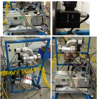
The referred pumping groups are inherent to all machines integrated on vacuum system at CERN’s complex. However, there are two possible configurations. In some cases, they can be fixed to the machine and, on other side, mobile groups may assure the pumping process. The last ones are distributed along the accelerators and are utilized where they are required. Once pumping
Figure 2.8: Front and back view of a CERN mobile pumping group.
2.2.3 VPGM control
The group during pumping and venting processes goes through different operational stages and, in each one of them, the coordination between all devices shall be a major concern.
The control process running in background on turbo-molecular pumping group may be de-scribed by a state machine diagram. In off mode, the automatic control is shutted down and all the devices remain in the current state in a way that can be manually operated. This condition, however, may cause hazardous consequences, thus, only the most experienced ones are able to manage the group. On other states, the machines are automatically controlled by the process and
it includes phases of pumping, venting, leak detection and even no operation [5]. Each one is yet
decomposed in several steps. The transition between states may occur automatically or may be requested by the operator. Although, in some operational conditions, the action indicated may be
blocked depending the status of the devices or the states involved [2]. In the figure2.9, it is present
Figure 2.9: Operation modes of VPGM [5].
As additional safety measure, there are also top-level interlocks [2]. They are implemented
to each valve, independently of the state machine, and unable manipulating actions when some conditions are satisfied. They can be of two kinds. Start-interlock maintain the current state of the valve when occurred. Full-interlock close the valve, if it is not, and remains at that state.
The whole control process of the pumping group is implemented on a PLC [5]. So, it shall
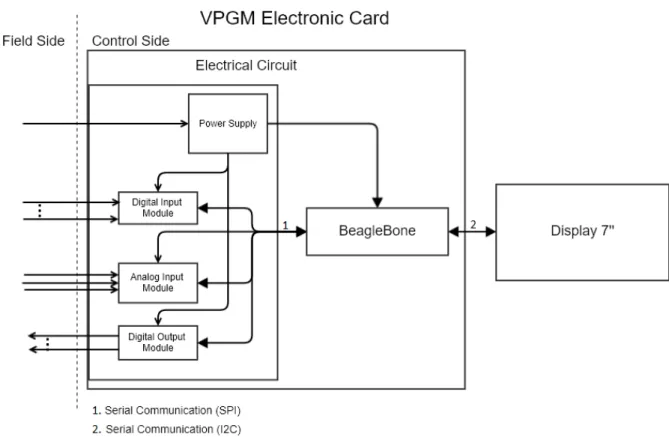
interact with all the devices that compose the pumping group. These interactions resume to receive feedback signals and send action commands. The electrical connections include six electronic-pneumatic valves, primary and turbo-molecular pumps, the bake-out system and, of course, a power supply. The type of interface is either digital, 0-24V, or analogical, 0-10V.
Although all the connections may be I/O based, some of them are based on Profibus, namely with the TMP controller and the vacuum gauge. In addition, the PLC also acts as Profibus master in the interface with a local touch panel, which represents human-machine interface.
Besides that, the pumping group is also integrated in an upper-level control system, vacuum
SCADA. This network relies on Profibus, but, here, local PLC acts as a slave device [2].
Figure 2.10: Hardware architecture [5].
Once the purpose of this thesis it is to develop an electronic card that can replace the PLC application, all the electrical compatibility with the connections previously described shall be assured. In order to guarantee, at least, the same level of computational capacity and safety, it is convenient the study of typical PLC characteristics as well as appropriated core solutions to the card.
2.3
Programmable logic controller (PLC)
A PLC is an industrial computer designed to control manufacturing processes. The first device surged at 1960’s years and the main purpose was replacing the relays switches, which dominate the industrial controlling scenarios until then. The relays application required the electrical wiring of these elements along the whole circuit of the system to be controlled in such a way that a spe-cific sensor position triggers a proper action on output actuators. Therefore, a particular solution
should be devised to each control application [6]. With the advent of PLCs, those problems were
overcame.
2.3.1 PLC architecture
PLC offers a control system that can be reusable in distinct control contexts. The control rules are set through a microprocessor-based system and accordingly with a logic view of the process,
i.e. if the state A was observed the action B must be taken [38]. These industrial devices rely on
operational principles like ones that support a typical personal computer. However, the first ones diverge by a more limited computational capacity, restricted to arithmetic and logic operations, a real-time system and, of course, a more robust hardware since they must support dust, vibrations,
noises and other adverse conditions inherent to industrial environments [6][39]. The advantages highlighted make the PLC a typical presence at industry nowadays.
In a simply perspective, PLC operation resumes to acquire inputs provided by external field devices (sensors, for instance), process them according with the instructions programmed at mem-ory and provide the respective outputs, which are sent to the actuators. To perform these sequence of operations, they must be composed by the following elements. Firstly, a CPU is required to compute the information based on the instructions configured at memory. Thus, a unit memory is also essential to register instructions, variables, timers and other parameters relevant to process. The configuration of memory implies a programming device, typically assured by an external PC running a software developed by the manufacturer. An additional communication module is also present to interact and exchange data with another PLC. Finally, input and output modules are a
must to interface with field devices and a power supply to feed the entire system [38].
Figure 2.11: PLC architecture [6].
The previous elements are necessarily integrated in the architecture of any device. However, depending the modularity associated to them, there are two distinct mechanical types of PLC. For one side, there is the single box (or brick) type. In such case, the units are all fixed in a monolithic structure and the number of interfaces available to connect to inputs and outputs are static and cannot be extended. Therefore, it is more suited for small applications. On the other side, there are the modular ones. Here, the units are all mounted at the same rack but independently. The rack is composed by several sockets where the units can be plugged. Therefore, the modules can be added or removed according with the application and so distinct elements can be mixed. The
connection among them is assured by connectors at the backplane [6].
2.3.2 IEC 61131
IEC 61131 is a standard developed to PLCs. It establishes the principles that regulate the whole lifecycle of these devices as well as the peripheral instruments that can be connected to them. It is divided in several parts and, among other aspects, includes the construction and functional re-quirements, tests and validations applied, operational conditions, safety issues and user guidelines [40].
Among all parts, there is one that deserves special emphasis, IEC 61131-3. This section specifies syntax and semantics of programming languages for programmable controllers aiming
to unify the software implementations through all manufacturers. The standard describes five possible languages: Instruction List (IL), Structured Text (ST), Sequential Function Chart (SFC),
Ladder Diagram (LD) and Function Block Diagram (FBD) [40].
It is possible to distinguish two groups. For one side, there are textual languages represented by ST and IL. ST allows a programming paradigm very similar to Pascal and IL is more logic and intuitive, directed for those who not feel too comfortable in programming. However, in both options following the process flow is not the easiest task. Thus, targeting a better system overview, there are graphical languages. LD is suitable for electrical engineers who prefer a graphical wiring representation of the installation, but any complex implementation beyond arithmetic operations won’t be feasible. SFC emphasizes the process states and the transitions conditions and provides a very clear representation. FBD is well fitted for repeated tasks because it allows the easy reuse of code fragments. Based on the aspects referred, it is easy to realize that the implementation of a control process on a PLC corresponds to a task that is not uniquely restricted to electrical engineers
or programming crew [38][7]. This is the purpose of the standard, user-friendly configuration of
programmable controllers.
Figure 2.12: IEC 61131-3 programming languages [7].
2.3.2.1 Software architecture
The standard establishes a hierarchical approach to programming structure on PLCs.
On the top position, there is the configuration block. It defines the PLC function on a plant
where can exists multiple PLCs with distinct purposes [8], being each one related to a specific
operation, in other words, represents the entire PLC system. A configuration is composed by resources. According with the standard, a resource allows all kind of interfaces, namely with I/O devices and even human-machine interface. So, a resource is a mandatory element and generally corresponds to a runtime application for instance, which can be allocated not just on PLC as
well as on personal computer that is used to programming work [41]. Generally, a resource may
include multiple tasks. A task defines the execution of specific actions and has some attributes, namely name, type (defines the execution behavior, i.e., if it is executed continuously, cyclically
or triggered by an event) and the priority (to define execution order) [8]. A task is related to
a program, whose implementation relies on function blocks and functions. A function block is located at a higher position than functions. The main difference is that the first ones can preserve
its internal state between executions and, that’s why, the result of each invocation is not always the same even if the input arguments don’t change, while on functions they return always the same
output value for one specific input array [8]. Due this, they occupy the bottom position of the
hierarchy.
The picture2.13depicts the previous ideas.
Figure 2.13: PLC software architecture [8].
2.3.2.2 Sequential Function Chart (SFC)
The operation of almost engineering systems is characterized by several states that represent dis-tinct systems conditions occupied by process while running. The state change is launched by a specific condition inherent to the system being modulated.
In engineer, the simpler approach to design such behavior is through state diagrams. They are composed by states, represented by circles, and linked to each other in a way that recreates the expected system flow, being associated a transition condition to each arrow. This is the most primitive tool to describe a process.
A standard and more sustainable design methodology is GRAFCET. The principle on it relies
is the same, but, here, a more clear and structured solution is obtained [42]. It is recreated reliably
the system flow from top to bottom and a functional overview of the whole control process is obtained.
To modulation purposes, three main elements must be considered: steps, actions and transi-tions. A step is the state associated to the system in one specific moment. When starting up, it
must be assigned a singular step to the process, flagged by a double line around that [43]. While
at a step, some tasks may be performed on the process. For that reason, a step may have linked to it actions. Such actions, however, can, for instance, being executed not during all step activation, but just at a specific time range, while activated or even after its deactivation. Such representation is obtained using action qualifiers. This is a letter which indicates what type of action is been
Table 2.1: Action qualifiers [27].
Qualifier Description Qualifier Description
N Non-stored SD Stored and time Delayed
R overriding Reset DS Delayed and Stored
S Stored SL Stored and time Limited
L time Limited P0 Pulse, falling edge
D time Delayed P1 Pulse, rising edge
P Pulse PN Pulse, Non-stored
Finally, there are transitions. They modulate a condition, passible to be evaluated as true or false, that must be verified to allow system evolution, i.e., step change. Between two consecutive steps shall always exist a transition.
In addition, several rules must be respected during design procedure. The whole process might be represented by one or several branches. Branches bifurcation is accomplished making use of specific structures, alternative and parallel branching. In first case, just one of the possible several branches included may be followed, beginning and finishing with a transition, while on parallel case all branches are executed simultaneously, beginning and finishing each branch with a step, considering that the process will only evolve when all of them are on last step. In both cases, the
junction of branches is possible through joint structures [43].
A process may end at a specific step or be described in loop. The last scenario is possible taking advantage of jumps, providing a transition between nonconsecutive steps. Its application,
however, should be cautious, since an overuse may difficult following process logic [43].
The SFC language is result of integration of GRAFCET modelling tool on IEC 61131
stan-dard as a graphical programming language [42]. For that reason, its support is common among
PLC manufacturers. The implementation is made respecting the rules previously defined and, consequently, it is just to migrate the process design to development environment almost with no change, preserving the intuitive overview and facilitating the debug procedure once running.
2.3.2.3 PLC scan cycle
Generally, when working with PLCs, the operator, through a specific manufacturer software, de-velops the code that reproduces the control action required to be performed. The program is then transferred to internal memory and, once running, will assure the intended process rules. To oper-ate, several inputs are required, provided by sensors for example, and another amount of outputs is generated, and sent to the actuators. The steps that occurs between these two stages depend from the code implemented.
Although the program located on memory set how occurs the processing step, the logic that supports the PLC operation is always the same. In first place, the inputs are acquired. All of them are registered simultaneously and uploaded to the input process image. This is important to assure
consistency among all input data and to safeguard that the signals are related to the same process moment. Once acquired, the data is processed and the outputs returned are saved on the output process image. Again, here, the commands are transferred simultaneously to the physical devices
at the end of the process. Once concluded, the cycle is repeated [44][9].
The presented behavior is inherent to any PLC and is called the scan cycle, as illustrated on picture2.14.
Figure 2.14: PLC scan cycle [9].
2.3.3 Input module
The input module of a PLC allows the electrical connection with field devices such as sensors or switches. Depending the device considered, signals generated may have distinct characteristics, i.e. discrete/digital signals where only two levels of voltage are possible or analog signals where the voltage or current varies continuously within possible parameters range, for instance 0-10V or
4-20mA signals, respectively [10]. Despite that, a PLC is a digital device and internally operates
at voltage mode, between 0V and internal voltage level, normally 5V. Externally, it is necessary to adjust the outside signals to these specifications. This way, there are distinct types of input modules, diverging not only in the number of connections allowed as well as in the interface supported.
On digital/discrete connections, the principal caution is related with voltage levels. The inputs
may have one of the various ranges that are possible, such as 5V, 24V, 110V and 240V [6]. When
selecting a module, this aspect must be considered in order to make it corresponds the input signals expected. Typically, these devices present internally an optocoupler to isolate the internal circuit from the outside device. Thus, the optocoupler plays a dual role, facilitating also the adjustment
of voltages levels [6][39]. In addition, to prevent an eventual connection of the input in reverse
mode and its consequent destruction, a diode is included in parallel with optocoupler, as exposed in picture2.15.
Figure 2.15: PLC DC input [10].
With analog signals, more aspects shall be considered. Since the internal operation of PLC relies on digital logic, the input signal must be acquired by an analog-digital converter (ADC). Here, the number of bits assumes special relevance. The choice will depend of the desired
mini-mum input variation that causes a change in one bit (called resolution) [10]. In addition, a module
commonly includes a unique ADC and several inputs whereby a multiplexer is also included, be-ing the channel selection internally controlled. Besides all that, it is convenient a previous filter to
prevent aliasing effects due to the possible high frequency of the process being sensed [39].
In some cases, a mix of analog signals may have to be connected to PLC (for instance, 4-20mA and 0-10V). To avoid the use of different modules, an external conditioning circuit may assure the compatibility. Typical topologies may be the use of a simple resistor (converting current in
voltage), voltage divider or an op-amp (to assure compatible voltage levels) [10].
2.3.4 Output module
The outputs of a PLC may be of distinct kinds depending of the load to be controlled and the behavior intended: relay, triac and transistor.
Figure 2.16: PLC output (adapted from [11]).
A relay output, as the denomination suggest, act as a typical relay allowing the switching operation with AC and DC signals and supporting large currents as well as significant voltage levels (up to 30V DC/2A and 240V AC/2A). It represents the more versatile option but supports a low switching frequency. To overcome such disadvantage, there is the transistor type. This provides a very high switching rating but it is only suitable for DC applications and lower currents,
typically not much higher than 300mA [10][38][10]. Finally, the triac output is equivalent to the
last but for AC applications.
The transistor and triac types are isolated from the internal circuit of PLC by optocouplers. In addition, it is also included in parallel with the output a protection diode. This device (also called
flyback diode) is used to protect the output driver when switching inductive loads. In such case,
the permanent commutation induces back EMF as consequence of magnetic phenomenon and the diode provides an alternative path to the current flow in such situation, avoiding the destruction of the output [10].
2.3.5 Source and sink
When dealing with digital I/O, two concepts should be clarified: sourcing and sinking. These classifications are strictly related with the direction in which flow the current relatively to the I/O
module [38].
An I/O is considered of sourcing type when provides the voltage to the circuit with the external device, i.e. the outside element is supplied by the interface module.
Figure 2.17: Input and output sourcing unit [10].
On the other side, a sinking I/O provides the ground to the circuit and so it is fed by the external device.
Figure 2.18: Input and output sinking unit [10].
2.3.6 Communication module
On an industrial scenario, a PLC might need to connect with many peripheral devices. For in-stance, to transfer the control program to memory unit, it is necessary the interface with a com-puter. Additionally, it is also common the communication with local human-machine interface (HMI) or remote PLCs to data exchange purposes. Thus, to assure the enumerated interfaces, a communication module is integrated in hardware architecture.
The communication module may provide diverse kinds of interaction. The simplest that is typically available is serial communication. It includes several standards, namely RS232, RS422,
RS423, RS485 [10]. The choice will depend of the distance implied and the characteristics of
surrounding environment. For example, a connection established through RS232 is not practicable to distances larger than 15m due to noise that corrupts the transmitted signal. On the other hand, RS485 represents a balanced transmission, i.e. based on the voltage difference between signals,
whereby higher speeds and distances are feasible [10].
However, in some situations, the simplicity inherent to serial interface may not be enough. To a more complex processing of data flowing and control of transmission, are used more robust systems of communication. Among all the industrial network systems available, the most known are the Fieldbuses and Ethernet.
2.3.6.1 Serial Peripheral Interface (SPI)
SPI is a protocol defined for serial communication. It is a synchronized approach intended for integrated circuits/chips and its main purpose is to provide a simple interface, overcoming the
synchronization shortcomings and complexity inherent to UART based protocols [12].
Considering the premises stated, any data exchange between devices is complemented by an external clock signal. The composition of such signal will dictate when the receptor must sample the acquired or to be sent data. Normally, it is characterized by several pulses and the sampling moment is dependent from clock polarity and phase, parameters that may be configured or fixed for each device. Regarding to this question, four SPI bus modes are valid.
Table 2.2: SPI bus mode [28]
SPI bus mode
Control Bit States
Description
Clock Polarity Clock Phase
0 0 1 Clock idle state = High, Transmit occurs ontransition from active to idle clock state.
1 0 0
Clock idle state = High, Transmit occurs on transition from idle to active clock state.
2 1 1
Clock idle state = Low, Transmit occurs on transition from active to idle clock state.
3 1 0 Clock idle state = Low, Transmit occurs ontransition from idle to active clock state.
Considering the clock source, two types of devices can be defined. The master is the one that generates the signal transmitted, existing just one per bus, while the slave receives and sends the data according with the rate imposed by it, being possible multiple presences of such stations on
the same bus [12]. So, there is no need to configure previously the transmission frequency. Despite
that, normally the value must within a specific range, provided on devices datasheet, as well as the number of pulses must be proportional to the amount of data (bits) being transmitted in both sides, implying a prior set of the bus. The master station defines the bus rules, being commonly associated to microcontrollers or similar platforms, while the slaves are more related to sensors
and equivalent devices [12].
SPI is a full-duplex protocol and, for such reason, there are two distinct data lines per bus. One carries the data sent by master to slave, being called MOSI (which stands for Master Output Slave Input), and the another one returns slave response, now called MISO, Master Input Slave Output [12].
When there are two or more slaves communicating with the same master, SPI bus must be shared. In this case, a device need to know when it is its time to exchange data, i.e., the information must be addressed. This is possible through a Select Slave line. In absence of communication, this
signal stands high, falling to low level at the beginning of transmission and remaining there until
the end [12]. To apply this approach to several slaves, it is needed a signal per slave.
Figure 2.19: SPI multiple slaves communication [12].
In last case, If the amount of slaves is huge, that solution may not be feasible or, at least,
too confuse. This can be overcame putting the stations on daisy chain configuration [12]. This
represents a ring topology where the output signal of the prior slave is connected to the input of next one and so one, being the last one of the chain connected to master. Here, one select line is enough, activating all devices at once. However, this kind of application requires the device support as well as a proper disposition of data being transmitted in order to be delivered to intended slave.
Figure 2.20: Daisy chain configuration [12].
2.3.6.2 Profibus
Profibusrepresents a standard communication largely widespread in automation applications. It
defines a format messaging that allows a high speed I/O communication, in such a way that is considered the fastest Fieldbus. It is characterized by its interoperability, allowing the interface among devices from distinct manufactures, and time reliability, enabling the prediction of time range inherent to transmission. A transmission occurs in a speed range extended since 9600Kbps until 12Mbps, depending from the distance intended, and it is established between two devices,
master and slave [45].
A master corresponds to an active station, i.e. when it has the permission to access the bus, may communicate without restrictions and outside permissions, prompting the interaction with the
slaves associated. Due this, a slave is considered a passive station, it is only allowed to respond to its master requests or acknowledge a reception. Generally, this role is played by peripheral devices such as sensors and actuators. The maximum number of devices permitted on a bus is limited to 126 [13].
In order to assure its interoperability, Profibus is supported by OSI model. This conceptual model groups the functions inherent to a network in layers, being each one related to a specific task
and operating independently of upper and lower ones [14]. To full support a telecommunication
system operation, there are seven layers, as below represented. Profibus standard only uses three
of them: application layer, data link layer and physical layer [45].
Figure 2.21: Profibus protocol stack [13].
At the application layer, it is possible to distinguish three versions of the standard: Profibus FMS, Profibus DP, Profibus PA. For one side, the Field Message Specification (FMS) was designed to allow the complex communication between PLCs and PCs whereby it is more suitable for the exchange of complex data and with less time restrictions. It is more applied on control level of automation, but, due to is low flexibility, it is currently abandoned and being replaced by Ethernet. The Profibus Decentralized Peripherals (DP) is the most common one. It assures high speed and time reliability in the communication between centralized equipment and distributed devices at factory floor, such as sensors and actuators. There are three variants of this version (V0, DP-V1, DP-V2) with a successive increasing in available communication features, but accomplished by a proportional complexity rising. Finally, the Profibus Process Automation (PA) is similar to the last one, however, more suitable to operate on hazardous environments, due to the power
limitation associated to physical transmission [13].
The data link layer is supported by the Fieldbus Data Link (FDL). The main functions are the control of the access to the communication bus and the monitoring of structure, integrity and safety of frames in transmission. As stated earlier, there are two types of devices associated to a
bus and, therefore, this channel must be properly shared in order to avoid collisions. In this case, this regulation is obtained through a hybrid mechanism, combining token passing with master-slave technique. Firstly, one master device only has the right to access the bus when it holds a software token, which is circulated in a ring topology among all masters. The communication between masters is not allowed, being uniquely restricted to token circulation. Once holding the token, its applicable a master-slave method in which a master station requests all its slaves in a limited period. This parameter is configured by user and it is the reason of Profibus deterministic behavior. Master-slave interaction may be of two kinds, namely SRD (send and request data with acknowledge) or SDN (send data with no acknowledge). The frame transmitted will depend of information and its purpose, but the full size never exceeds 255 bytes, a maximum of 244 bytes to
payload and a header of 11 bytes. Each character is codified with 11 bits [13].
Figure 2.22: Profibus character codification [14].
Finally, the physical layer is inherent to electrical transmission of the data through the bus. In
Profibus DP, the communication relies on RS485 standard [14].
Additionally, the interaction between master and slave stations is only possible after an initial configuration in order to assign a valid address to each device and set the interaction parameters. The identification and specifications of a station (baud rate, data length, number of inputs and outputs) are stated in GSD file, a datasheet of an electronic device. This setting state is assured by another type of master station, a class 2 master. It acts as a supervisory element, playing configuration actions and diagnosis purposes. After this initial validation step, the devices can
communicate and operate at the normal state [14].
In picture2.23, it is represented a state diagram which illustrates the operation of Profibus DP
slave.
2.3.6.3 Profibus implementation
The Profibus DP offers a fast data exchange combined with a deterministic medium access. De-spite these appealing facts, the protocol implementation requires specific hardware and software with a high acquisition cost. Thus, the application domain is commonly limited to professional
and commercial ends [46].
Traditionally, the interface with a Profibus network is made through specific interface mod-ules. These elements assume a node role on fieldbus connection, described by an address, and allows the Profibus coupling among remote field devices. They implement the protocol layers and structure the exchanged information in both ways according with that. The module must be chosen considering the type of station desired, master or slave.
Another kind of support is based on application specific integrated circuits (ASICs). In this case, dedicated chips implement the lower two layers of Profibus stack and handle the medium access, requiring, however, a RS485 transceiver to interface with the fieldbus physical layer. Ad-ditionally, a host controller, typically microcontroller based, implements the application level layer
and interacts, through serial or parallel interface, with ASIC [47]. This option represents a small
size and not quite expensive alternative, allowing a tailor-made solution to the user who can build
his own hardware architecture [48].
In order to offer a cheaper alternative than the Profibus market, there are some developments
of open-source solutions [49][46]. The main purpose of these projects is to minimize the need
of hardware and build a software-based solution to protocol stack, supported by a wide range of
systems platforms. In this context, it is remarked the project indicated at [50]. This presents an
implementation of a Profibus master. Currently, it is on development state, thus, the full imple-mentation of protocol stack wasn’t yet achieved. However, it is indicated that the communication with a Profibus slave was made successfully and, consequently, physical layer is functional and represents a good basis to posterior work. With this solution, instead of expensive hardware, it is just required a RS-485 interface and the costs would be minimal.
2.4
Soft-PLC
The PLC represents the most widespread solution in industry control scenarios. A hardware suitable for the most adverse environment, a hard real-time software with a wide range of pro-grammable languages and the possibility of connection with diverse peripheral devices make them the most preferable choice on automation context. However, its use also implies some drawbacks. These result from the increasing inconsistency among the manufactures, specific software
asso-ciated to each company and expensive acquisition cost [51]. To avoid these disadvantages and
replace its utilization, the use of soft-PLC is becoming a reality.
Soft-PLC consists of a control software engine designed to the conventional CPUs that equips a PC and implements the characteristic features of a traditional PLC, i.e. using the hardware
and processing unit of a PC it is possible to suppress the basic function of a PLC. This PC-based solution allows a higher computation capability and a versatile support of communication interface. In addition, the portability of these devices permits higher flexibility and small size
regarding to space requirements [52][53]. Besides all these facts, a soft-PLC is based on the
IEC 61131 standard whereby the programming paradigm inherent to a PLC is also supported and facilitates program development. The associated cost-effective and openness architecture make this a very feasible alternative. Although the advantages stated, the software running on a PC is
not suitable for real-time operation [51]. So, a higher reaction time shall be expected whereby
special careful must be taken to ensure that the normal operation of controlled process is not significantly affected.
CODESYS is a software platform for industrial automation technology. It offers a full support of all levels of automation control processes. At engineering level, it possibilities the configuration and programming of automation devices as well as appropriated tools to a correct debug and visualization of data. At device level, it provides a running system to converts a PC-based or embedded system into an industrial controller including optional add-on modules to interact with any I/O device. In addition, all the development software supports IEC 61131 standard. Therefore, the large support and the possibility of running on diverse platforms make this a common choice to soft-PLC role. The company provides a trial version that allows all functionalities, but with
time limitations. A premium license has a cost depending from desired platform [54].
CODESYS also offers a wide support of fieldbus. However, to interface with industrial net-works additional modules may be required. In Profibus case, the integration implies the
installa-tion of physical Profibus terminals [55] and the acquisition of supplementary software controller
to register the device as a station. Still, different packages are required to act as master or slave
station [56][57]. The purchase value of such gateways combined with extra software licenses cost
make this interface approach too expensive on a low-cost project.
Furthermore, another option may be the TwinCAT software released by Beckoff company
[58]. Here, the automation control experience is very similar to the last one, including the
sup-port of engineering and device levels with diverse functions available to the user, but with more restrictions in platform application, being limited to windows-based environments. A full function software is freely available for 30 days. For a further use, a premium license must be acquired.
Additionally, there are also open-source options such as Beremiz [59]. However, generally,
they represent projects in progress that may not achieve a sufficient stable solution for a real automation application.
2.5
Single-board computer (SBC)
The main element of a PLC operation is the processing unit. This module assures the execution of program instructions implemented at memory unit, the acquisition of inputs and the generation of respective outputs. So, an architecture to automation process control non-based on PLC implies
![Figure 2.5: Useful range of standard pumps [4].](https://thumb-eu.123doks.com/thumbv2/123dok_br/15940266.1096193/28.892.187.659.486.708/figure-useful-range-of-standard-pumps.webp)
![Figure 2.6: Pressure gauges application [4].](https://thumb-eu.123doks.com/thumbv2/123dok_br/15940266.1096193/29.892.214.713.141.481/figure-pressure-gauges-application.webp)
![Figure 2.13: PLC software architecture [8].](https://thumb-eu.123doks.com/thumbv2/123dok_br/15940266.1096193/36.892.228.622.295.537/figure-plc-software-architecture.webp)
![Figure 2.16: PLC output (adapted from [11]).](https://thumb-eu.123doks.com/thumbv2/123dok_br/15940266.1096193/40.892.249.609.148.473/figure-plc-output-adapted-from.webp)
![Figure 2.21: Profibus protocol stack [13].](https://thumb-eu.123doks.com/thumbv2/123dok_br/15940266.1096193/44.892.190.642.393.677/figure-profibus-protocol-stack.webp)
![Figure 3.1: BeagleBone Green overview [15].](https://thumb-eu.123doks.com/thumbv2/123dok_br/15940266.1096193/52.892.199.656.148.429/figure-beaglebone-green-overview.webp)
![Figure 3.2: BeagleBone LCD display cap [16].](https://thumb-eu.123doks.com/thumbv2/123dok_br/15940266.1096193/53.892.148.791.328.529/figure-beaglebone-lcd-display-cap.webp)
![Figure 3.5: Serializer input protection circuit (adapted from [17]).](https://thumb-eu.123doks.com/thumbv2/123dok_br/15940266.1096193/57.892.334.582.348.727/figure-serializer-input-protection-circuit-adapted.webp)
