Advances in Mechanical Engineering 2015, Vol. 7(7) 1–10
ÓThe Author(s) 2015 DOI: 10.1177/1687814015594124 aime.sagepub.com
Numerical analysis and parametric
study of multilayered microchannel
heat sinks
Lin Lin
1, Min-Xin Deng
1, Xin-Xin Zhang
1and Xiao-Dong Wang
2,3Abstract
A three-dimensional solid–fluid conjugated model is used to investigate and optimize the performances of two-, three-, and four-layered microchannel heat sinks. In the optimization process, constraints of fixed total pumping power and fixed total channel height are adopted, and the thermal resistance and bottom wall temperature uniformity are taken as the objective functions. The flow configuration, channel height, and pumping power in each layer are optimized. The results show that more uniform temperature distribution and lower thermal resistance occur at flow configuration (0, 1) for the two-layered microchannel heat sink, (0, 1, 1) for the three-layered microchannel heat sink, and (0, 1, 1, 1) for the four-layered microchannel heat sink. The channel height and pumping power in the bottom layer are dominant over those in the other layers. The optimal design requires a smaller bottom channel height and a higher pumping power than the average value in each layer. The multilayered microchannel heat sink with more layer numbers can achieve a more uniform bottom wall temperature and can also lead to a reduction in the thermal resistance.
Keywords
Multilayered microchannel, heat sink, thermal resistance, numerical analysis, parametric study
Date received: 22 December 2014; accepted: 8 April 2015
Academic Editor: Mohammad Reza Salimpour
Introduction
With the advances in microelectronic mechanical sys-tem (MEMS) technology, the sizes of microelectronic devices become more and more compact, and their power becomes higher and higher. This results in tre-mendous increases in the power densities and associated heat fluxes generated in these devices. Thus, effective methods for heat removal become indispensable for the thermal management of MEMS. Microchannel heat sink (MCHS) is one of the most important cooling methods of micro devices due to their advantageous heat transfer performance such as compact size, smaller volume per heat load, lower coolant requirements, and lower operational cost, as compared with conventional heat sink.1 However, there still exist many disadvan-tages including high pumping power requirement and
poor uniformity of temperature distribution at the cool-ing surface. Recently, Xie and colleagues,2–6 Hajmohammadi et al.,7–12and Wang and colleagues13–18 conducted many relevant works to improve the cooling
1School of Mechanical Engineering, University of Science and Technology
Beijing, Beijing, China
2State Key Laboratory of Alternate Electrical Power System with
Renewable Energy Sources, North China Electric Power University, Beijing, China
3Beijing Key Laboratory of Low-grade Energy Multiphase Flow and Heat
Transfer, North China Electric Power University, Beijing, China
Corresponding author:
Xiao-Dong Wang, State Key Laboratory of Alternate Electrical Power System with Renewable Energy Sources, North China Electric Power University, Beijing 102206, China.
Email: [email protected]
performance of the MCHS. For example, Xie and col-leagues2–6studied the wavy MCHS and proposed some new MCHS structures with multistage bifurcations or with constructional vertical Y-shaped bifurcation plates. Hajmohammadi et al.7–12 optimized the struc-ture of the heat sink and adopted power-law fluid as the coolant. In addition, the flow stability and the vis-cous dissipation effect in microchannels have been investigated using the semi-analytical method and gra-dient energy method in Hajmohammadi et al.,8,12and these methods can also be used to study the flow stabi-lity in the MCHS.
To improve the cooling uniformity of the MCHS, Vafai and Zhu19for the first time proposed the design of two-layered MCHS. In the new structure, coolant flows reversely in the top and bottom channels for tem-perature compensation between the two channels, which leads to a lower pressure drop and a more uni-form temperature distribution as compared with one-layered MCHS. Subsequently, many researchers carried out optimization studies on the two-layered MCHS,20–
26
and the optimized parameters include the solid mate-rials of heat sink, coolant, flow direction, channel shape and size, velocity ratio between two channels, and so on. Based on the various designs of the two-layered MCHS, researchers further constructed multilayered MCHS. Wei and Joshi27 adopted a three-dimension thermal resistance model with the box optimization algorithm to optimize the geometry parameters of mul-tilayered MCHS. The effect of layer number on the heat sink performance was investigated in their work. It was found that the one-layered MCHS achieves the best performance with the pumping power of 0.01 W. Lei et al.28conducted an experimental study on the per-formance of cooper multilayered MCHS, and their results indicated that the thermal resistance of heat sink decreases with the increase in layer number, but the decrease degree becomes smaller. Afterward, Wei and Joshi29and Lei et al.30performed further studies on the influence of layer number on the performance of multi-layered MCHS under various conditions.
It is worth noting that the multilayered MCHS in Wei and Joshi27,29and Lei et al.28,30is stacked by many single-layered MCHS with the same size; thus, the total height of the heat sink is not a fixed amount when the layer number varies. However, under real circum-stances, only a very limited cooling space is available for assembling the heat sink. Moreover, the cooling load in each layer of the multilayered MCHS is differ-ent, so that different coolant flow rates or pumping power for each layer should be adopted. Unfortunately, the pumping power or coolant flow rate in each layer was assumed to be the same in Wei and Joshi27,29and Lei et al.28,30
In this article, a three-dimensional solid–fluid conju-gated model is developed to investigate the flow and
heat transfer characteristics in the multilayered MCHS at a constant total pumping power of 0.05 W and a con-stant total channel height of 700mm. The effects of flow configuration, channel height, and pumping power in each layer on the heat sink performance are analyzed, and the corresponding optimal values for these para-meters are obtained.
Geometry and material properties for
multilayered MCHS
The MCHS is made of silicon, and water is used as a coolant. The material property parameters are
ks= 148 W m2 1
K21
, kl= 0.613 W m2 1
K21
, ml=
0.000855 kg m21 s21, rl= 997 kg m23, and cpl=
4179 J kg21 K21, wherek is the thermal conductivity,
mis the viscosity,ris the density, andcpis the specific
heat. The subscripts s and l denote solid rib and liquid coolant, respectively. The heat sink has a dimension of
Lx 3Lz3Ly= 10 3103 0.9 mm3. The optimal geometric parameters for the one-layered MCHS have been obtained in our previous work.13For the purpose of comparison, the present multilayered MCHSs adopt the same parameters, such as channel number of
N= 73, total channel height of Hc= 700mm, channel
width of Wc= 85 mm, and rib width of Wr= 26mm.
Only one element is taken as the computational domain due to the symmetry of the heat sink, as shown in Figure 1.
Thermal resistance and maximum bottom wall tem-perature difference are two important indicators to evaluate the cooling performance of the heat sink. The thermal resistance is defined as
RT=TmaxTmin qwA
=TmaxTmin qwLxLz
ð1Þ
where Tmax andTmin=Tin are the highest and lowest
temperatures observed in the heat sink, and A=LxLz is the base area of the heat sink. The maximum bottom wall temperature difference is defined as
DTb=Tb, maxTb, min ð2Þ
whereTb,max=TmaxandTb,minare the maximum and
minimum temperatures on the bottom wall.
Numerical model
coolant and its inlet Reynolds number is always lower than 500 for all simulation cases, the assumption of incompressible and laminar flow is reasonable. Our previous study13showed that constant material proper-ties only lead to about 4% deviation of the thermal resistance compared with temperature-dependent prop-erties. In addition, previous studies13,19,20also indicated that the gravity and viscous dissipation can be safely ignored in microchannels. Although the contact ther-mal resistance between the heat sink and cooled surface deteriorates the cooling performance of the heat sink, its effect can be minimized using the heat-conducting adhesive with high thermal conductivity. The governing equations are descried briefly as follows:
Continuity equation for the coolant
r ~V=0 ð3Þ
Momentum equation for the coolant
rl ~V rV~= rp+mlr2V~ ð4Þ
Energy equation for the coolant
rlcpl ~V rTl=klr 2
Tl ð5Þ
Energy equation for the solid rib
ksr 2
Ts=0 ð6Þ
where~V is the velocity vector,pis the coolant pressure, andTis the temperature.
The boundary conditions adopted are as follows: the coolant inlet temperature in each layer remains a con-stant value ofTin= 293K; the outlet pressure in each
layer is assumed to be 1.013253 105 Pa; no-slip
condition is specified to all channel walls; the coupled boundary conditions are adopted on the fluid–solid interface, that is, the temperature and heat flux are con-tinuous on these interfaces; and adiabatic boundary condition is applied to the outside walls and symmetric surfaces. In addition, the simulations are performed at constant bottom wall heat flux ofqw= 100 W m22and
a constant total pumping power ofO= 0.05 W.
The model uses nonuniform distributed grid. The present code is tested for grid independence by calculat-ing the fluid temperature along the flow channel center-line. It is found from Figure 2 that a grid size of 403 45340 for the two-layered heat sink ensures a grid-independent solution. For the other heat sinks dis-cussed in this work, the grid independences are also examined in preliminary test runs.
The experimental data of the two-layered MCHS reported in Wei et al.’s22study are used to validate the Figure 1. Schematics of MCHSs: (a) one-layered MCHS, (b) two-layered MCHS, (c) three-layered MCHS, and (d) four-layered MCHS.
present model. The geometric structure and operating conditions of the heat sink are assumed to be the same with those in Wei et al.22Figure 3 shows the predicted and measured bottom wall temperatures for four cool-ant flow rates. The deviations between the predicted and measured results are less than 1K. Thus, the pres-ent model can be used accurately to predict the multi-layered MCHS performance.
Results and discussion
Effect of flow configuration
Unlike the one-layered MCHS, the multilayered MCHS has multiple inlets and outlets. Previous stud-ies21–23have shown that the flow configuration in each layer affects the heat dissipation and temperature
uniformity of the two-layered MCHS significantly. It can be expected that the flow configuration also affects the performance of the three- and four-layered MCHSs. In the present simulations, number 0 stands for the positivex-direction, while number 1 denotes the negativex-direction. Thus, when the flow configuration is taken as (0, 1, 0) for the three-layered MCHS, it means that the coolant flows along the positivex -direc-tion in the bottom and top layers, while the coolant flows along the negativex-direction in the middle layer. It should be noted that the three-layered MCHS with flow configuration (0, 1, 0) or (1, 0, 1) has the identical performance due to the symmetry. Consequently, only flow configurations (0, 1) and (1, 1) for the two-layered MCHS; (0, 0, 0), (0, 1, 0), (0, 0, 1), and (0, 1, 1) for the three-layered MCHS; and (0, 0, 0, 0), (0, 1, 0, 0), (0, 0, 1, 0), (0, 0, 0, 1), (0, 1, 1, 0), (0, 1, 0, 1), (0, 0, 1, 1), and (0, 1, 1, 1) for the four-layered MCHS are investigated here. It is restated that a constant total pumping power of O= 0.05 W and a constant total channel height of
Hc= 700 mm are used in the present simulations. In
this section, the pumping power and channel height in each layer are assumed to be the same, that is, On1=
On2= ... =Onn=O/n and Hn1=Hn2= ... = Hnn=Hc/n, wheren denotes the layer number of the
multilayered MCHS.
The thermal resistances and bottom wall tempera-ture differences at various flow configurations for the one-layered and multilayered MCHSs are listed in Table 1. It can be seen that the flow configuration has a great influence on the multilayered MCHS perfor-mance. Taking the four-layered MCHS for example, when the flow configuration is changed from (0, 0, 0, 0) to (0, 1, 1, 1), the thermal resistance is reduced by Table 1. Thermal resistances and bottom wall temperature differences at various flow configurations for the one-layered and multilayered MCHSs.
Heat sink Flow configuration RT(K W21) DTb(K)
One-layered MCHS (0) 0.1437 8.97
Two-layered MCHS (0, 0) 0.1448 9.44
(0, 1) 0.1364 7.35
Three-layered MCHS (0, 0, 0) 0.1472 9.82
(0, 1, 0) 0.1436 8.07
(0, 0, 1) 0.1434 8.86
(0, 1, 1) 0.1362 6.36
Four-layered MCHS (0, 0, 0, 0) 0.1500 10.24
(0, 1, 0, 0) 0.1464 8.37
(0, 0, 1, 0) 0.1491 9.55
(0, 0, 0, 1) 0.1488 9.76
(0, 1, 1, 0) 0.1468 7.16
(0, 1, 0, 1) 0.1479 7.70
(0, 0, 1, 1) 0.1436 8.35
(0, 1, 1, 1) 0.1383 5.59
MCHS: microchannel heat sink.
Number 0 in the column of flow configuration denotes the positivex-direction, while 1 denotes the negativex-direction.
7.79%, and the bottom wall temperature difference is decreased by 45.4%. Among all the flow configura-tions, the thermal resistance and bottom wall tempera-ture difference are the highest if the flow direction of the coolant in each layer is taken as the same, that is, (0, 0) for the two-layered MCHS, (0, 0, 0) for the three-layered MCHS, and (0, 0, 0, 0) for the four-three-layered MCHS. It is worth noting that the performances for flow configurations (0, 0), (0, 0, 0), and (0, 0, 0, 0) are even worse than those for the one-layered MCHS, indi-cating that only simple dividing of a one-layered MCHS into a multilayered MCHS cannot improve the heat sink performance.
The best flow configuration is (0, 1) for the two-layered MCHS, (0, 1, 1) for the three-two-layered MCHS, and (0, 1, 1, 1) for the four-layered MCHS, which can reduce thermal resistance of the heat sink and improve the temperature uniformity on the bottom wall signifi-cantly (Table 1). Levac et al.21 and Xie et al.23 pre-sented that for the two-layered MCHS with the same geometry and pumping power in each layer, the parallel flow is the best flow configuration to improve the cool-ing performance at low flow velocity, while the counter flow is the best one at high flow velocity, and it can always achieve a better temperature uniformity at both the low and the high flow velocities. Moreover, Levac et al.21pointed out that a critical Re for transition from the parallel flow to the counter flow is 100. In the pres-ent two-layered MCHS, the channel height and pump-ing power in the top and bottom layers are the same, the corresponding Re is 135.67 higher than the critical value reported by Levac et al.; thus, the optimal flow configuration should be (0, 1), which agrees well with the present simulation.
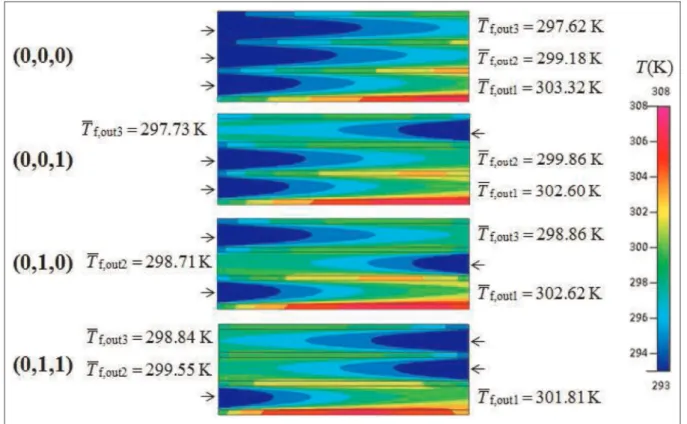
Figure 4 shows the temperature contours of the three-layered MCHS in thex–ymiddle cross section for various flow configurations. For flow configuration (0, 0, 0), the bottom wall temperature gradually increases along the flow path, and the highest temperature appears at the channel outlet with x=Lx; hence, the
temperature uniformity is the worst for this flow con-figuration. When the flow direction of the coolant for the middle layer and/or top layer is changed, the cool-ant in these layers will inevitably cool the bottom layer in the outlet region of the bottom layer due to lower coolant inlet temperature, which is referred to as the cooling effect. Conversely, a heating effect will be observed in the inlet region of the bottom layer because the coolant outlet temperature in the middle layer and/ or top layer is higher than the coolant inlet temperature in the bottom layer. Thus, more uniform temperature distribution and lower thermal resistance occur for flow configurations (0, 1, 0), (0, 0, 1), and (0, 1, 1), and the best flow configuration for the three-layered MCHS is (0, 1, 1). Similarly, as long as the flow direction in the second, third, and/or fourth layer is changed for the four-layered MCHS, the performance can be improved, and the best performance will occur for flow configura-tion (0, 1, 1, 1).
Figure 4 also indicates that the flow configuration affects the distribution of heat dissipation in each layer for the three-layered MCHS significantly. For all flow configurations (0, 0, 0), (0, 1, 0), (0, 0, 1), and (0, 1, 1), the outlet temperatures in the bottom layer are all higher than those in the middle and top layers, which means that the bottom layer dissipates most of the heat. The outlet temperature in the bottom layer is the high-est for flow configuration (0, 0, 0) and then followed by (0, 1, 0), (0, 0, 1), and (0, 1, 1). For flow configuration (0, 1, 1), the outlet temperature is 301.81K for the bot-tom layer, 299.55K for the middle layer, and 298.84K for the top layer. The corresponding heat dissipations (=rcpuin(Tout2Tin)) are 0.59, 0.43, and 0.39 W,
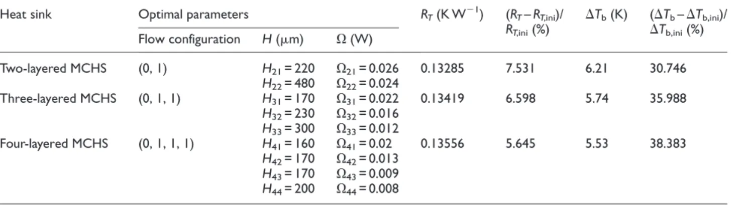
respec-tively. As compared with the other three flow config-urations, the heat dissipation in each layer is the most uniform for flow configuration (0, 1, 1). Table 1 shows that the thermal resistance has the same dependence on the flow configuration as the outlet temperature in the bottom layer. It can be concluded from the above results that when the geometry and pumping power in Table 2. Optimal parameters for various multilayered MCHSs.
Heat sink Optimal parameters RT(K W21) (RT–RT,ini)/ RT,ini(%)
DTb(K) (DTb–DTb,ini)/
DTb,ini(%)
Flow configuration H(mm) O(W)
Two-layered MCHS (0, 1) H21= 220 O21= 0.026 0.13285 7.531 6.21 30.746 H22= 480 O22= 0.024
Three-layered MCHS (0, 1, 1) H31= 170 O31= 0.022 0.13419 6.598 5.74 35.988 H32= 230 O32= 0.016
H33= 300 O33= 0.012
Four-layered MCHS (0, 1, 1, 1) H41= 160 O41= 0.02 0.13556 5.645 5.53 38.383 H42= 170 O42= 0.013
H43= 170 O43= 0.009 H44= 200 O44= 0.008
each layer are the same for a multilayered MCHS, the optimal cooling performance can be achieved by such a flow configuration which offers a more uniform heat dissipation in each layer.
Effect of channel height
This section discusses the effect of channel height in each layer on the multilayered MCHS performance. The flow configuration is assumed to be the optimal one obtained in section ‘‘Effect of flow configuration,’’ and the pumping power in each layer is equally distrib-uted. The channel heights are investigated in the follow-ing order. Takfollow-ing the three-layered MCHS for example, the bottom channel height H31first varies from 100 to
500 mm, while the middle and top channel heights remain as the same value of H32=H33= (7002H31)/
2; once the optimalH31is obtained, the middle channel
height starts to vary from 100 to 400mm with the opti-mal (H31)optandH32= 7002(H31)opt2H32.
Figures 5–7 show the dependence of thermal resis-tance on channel heights for the two-, three-, and four-layered MCHSs, respectively. For all simulation cases, the thermal resistance first decreases and then increases with the increase in channel height, indicating that each channel in the multilayered MCHS has an optimal height. The optimal channel heights for the multi-layered MCHSs are listed in Table 2.
Figure 8 shows the centerline temperature distribu-tion on the bottom wall at various H31 for the
three-layered MCHS. It is restated that the pumping power in each layer remains the same in the present simula-tions. As a result, when the bottom channel height increases, the flow rate in the bottom layer increases, and hence, more heat will be dissipated by the bottom layer. For a very small channel height of H31= 100
mm, the middle and top layers dissipate much more Figure 4. Temperature contours of the three-layered MCHS in thex–ymiddle cross section (not to scale).
heat than the bottom layer; increasing H31 enhances
the heat dissipation by the bottom layer and hence leads to a more uniform heat dissipation in each layer. Conversely, for a very large channel height of
H31= 500 mm, more heat is dissipated by the bottom
layer; thus,H31needs to be reduced to achieve a more
uniform heat dissipation in each layer. Consequently, there certainly exists an optimal H31, which can make
sure that each layer dissipates almost the same heat. For the present simulation, the optimalH31is found to
be 170 mm. As mentioned in section ‘‘Effect of flow configuration,’’ the uniform heat dissipation in each layer of the multilayered MCHS can lead to a low ther-mal resistance and a more uniform temperature distri-bution on the bottom wall. Thus, whenH31= 170mm,
the heat sink has the lowest thermal resistance of 0.1351 W K21
(Figure 6) and the most uniform bottom wall temperature distribution of DTb= 5.532K
(Figure 8).
A comparison of Figures 5–7 shows that the bottom channel height has more significant effect on the heat
sink performance than the other channel heights. For example, the thermal resistance corresponding to the optimal H31= 170 mm is 0.1351 W K21, which is
reduced by 13.06% as compared with the maximum thermal resistance of 0.1554 W K21
(H31= 500 mm).
However, with the optimalH31= 170mm, the thermal
resistance corresponding to the optimalH32= 230mm
is 0.1350 W K21
, which is reduced by only 2.10% as compared with the maximum thermal resistance of 0.1379 W K21
(H32= 100mm). Moreover, Figures 5–7
and Table 2 show that the optimal bottom channel height is H21= 220 mm for the two-layered MCHS, H31= 170 mm for the three-layered MCHS, and H41= 160 mm for the four-layered MCHS, which is
always smaller than the average channel height.
Effect of pumping power
This section analyzes the effect of pumping power in each layer on the multilayered MCHS performance. During the simulations, the optimal flow configura-tions in section ‘‘Effect of flow configuration’’ and the optimal channel heights in section ‘‘Effect of channel height’’ are adopted.
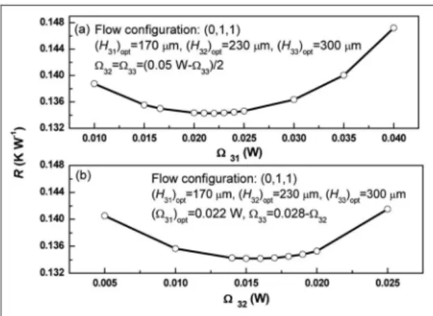
The pumping power for each layer is optimized in the same order as the channel height. Figures 9–11 show the dependence of thermal resistance on pumping power for the two-, three-, and four-layered MCHSs, respectively. For all simulation cases, as the pumping power increases, the thermal resistance always first reduces and then increases; thus, an optimal pumping power for each layer can be obtained (Table 2). The optimal pumping power in the bottom layer are O21= 0.026 W for the two-layered MCHS,
O31= 0.022 W for the three-layered MCHS, and
O41= 0.02 W for the four-layered MCHS, which is
always larger than the average pumping power; thus, Figure 6. Effect of channel height on thermal resistance of the
three-layered MCHS.
Figure 7. Effect of channel height on thermal resistance of the four-layered MCHS.
the optimal design for the multilayered MCHS requires a higher pumping power in the bottom layer. In addi-tion, Figures 9–11 also demonstrate that the pumping power in the bottom layer is dominant over the pump-ing powers in the other layers. For example, the ther-mal resistance for the optimal O41= 0.02 W is
0.1361 W K21
, which is reduced by 7.36% as compared with the maximum thermal resistance of 0.1469 W K21
(O41= 0.005 W). However, when optimalO41= 0.02 W
is adopted, the thermal resistance for the optimal O42= 0.013 W is 0.1356 W K21, which is reduced by
3.00% compared with the maximum thermal resistance of 0.1398 W K21
(O42= 0.022 W). Similarly, when
opti-mal O41= 0.02 W and optimal O42= 0.013 W are
adopted, the thermal resistance for the optimal O43= 0.009 W is reduced by only 1.56%.
Figure 12 shows the heat flux distributions on the channel wall for the three-layered MCHS at three dif-ferentO41= 0.01, 0.022, and 0.04 W, which correspond
to the three cases in Figure 10(a). Only the negative heat flux is shown in Figure 12. The negative heat flux means that the coolant temperature is lower than the rib temperature, so that the heat will be transferred from the coolant to the rib. Consequently, the negative heat flux has an unfavorable effect on the cooling per-formance of heat sink. As shown in Figure 12, the neg-ative heat flux mainly occurs in the region of channel outlet. When O41 increases, the area of the negative
heat flux is reduced for the bottom layer, while it is enlarged for the middle and top layers. As a result, there exists an optimal O41, which can balance the
dis-tribution of negative heat flux in the three layers and hence achieve the optimal heat sink performance.
Comparison of the optimal performance between
one-layered and multilayered MCHSs
Table 2 shows the optimal parameters, the correspond-ing thermal resistance, and the bottom wall tempera-ture difference for the two-, three-, and four-layered MCHSs, respectively. The thermal resistance and bot-tom wall temperature difference of the multilayered MCHSs are all lower than those of the one-layered MCHS. Among the multilayered MCHSs, the two-layered MCHS has the lowest thermal resistance of
RT= 0.1328 W K21; however, its temperature unifor-mity is the worst with bottom wall temperature differ-ence ofDTb= 6.21K. On the contrary, the four-layered
MCHS can achieve the best temperature uniformity with DTb= 5.53K, but its thermal resistance is the
highest (RT= 0.1356 W K2 1
).
Conclusion
In this work, a three-dimensional solid–fluid conjugate model is used to analyze the flow and heat transfer Figure 9. Effect of pumping power on thermal resistance of
the two-layered MCHS.
Figure 10. Effect of pumping power on thermal resistance of the three-layered MCHS.
characteristics of the multilayered MCHSs at a con-stant total pumping power and a concon-stant total channel height. The model is validated well by comparing the predicted bottom wall temperature with the experimen-tal data. The flow configuration, channel height, and pumping power in each layer are optimized. The main conclusions are as follows:
1. The flow configuration has significant effect on the multilayered MCHS performance. Among all the flow configurations, the thermal resis-tance and bottom wall temperature difference are the highest if the flow direction of the cool-ant in each layer is taken to be the same, and they are even worse than those for the one-layered MCHS. The most uniform temperature distribution and the lowest thermal resistance occur at flow configuration (0, 1) for the two-layered MCHS, (0, 1, 1) for the three-two-layered MCHS, and (0, 1, 1, 1) for the four-layered MCHS.
2. For the multilayered MCHS, there exists an optimal channel height for each layer. However, the bottom channel height has more significant effect than the other channel heights, and the optimal bottom channel is always smaller than the average channel height.
3. Similarly, when the total pumping is fixed, each layer has an optimal pumping power to achieve the optimal heat sink performance. The pump-ing power in the bottom layer is dominant over the pumping powers in the other layers, and the optimal design requires a higher pumping power in the bottom layer than the average pumping power.
4. As the layer number increases, the multilayered MCHS can achieve a more uniform bottom wall temperature and can also lead to a reduction in the thermal resistance.
Declaration of conflicting interests
The authors declare that there is no conflict of interest.
Funding
This study was supported by the National Natural Science Foundation of China (no. 51176010), the 111 Project (no. B12034), Program for New Century Excellent Talents in University (no. NCET-11-0635), and the Fundamental Research Funds for the Central Universities (no. 13ZX13).
References
1. Tuckerman DB and Pease RFW. High-performance heat sinking for VLSI. IEEE Electr Device L 1981; 2: 126–129.
2. Xie GN, Chen ZY, Sunden B, et al. Comparative study of flow and thermal performance of liquid-cooling paral-lel-flow and counter-flow double-layer wavy microchan-nel heat sinks.Numer Heat Tr A: Appl2013; 64: 30–55. 3. Xie GN, Chen ZY, Sunden B, et al. Numerical
predic-tions of flow and thermal performance of water-cooled single-layer and double-layer wavy microchannel heat sinks.Numer Heat Tr A: Appl2013; 63: 201–225. 4. Xie GN, Zhang FL, Sunden B, et al. Constructal design
and thermal analysis of microchannel heat sinks with multistage bifurcations in single-phase liquid flow. Appl Therm Eng2014; 62: 791–802.
5. Li YL, Zhang FL, Sunden B, et al. Laminar thermal per-formance of microchannel heat sinks with constructal vertical Y-shaped bifurcation plates. Appl Therm Eng
2014; 73: 183–193.
6. Zhang RP, Chen ZY, Xie GN, et al. Numerical analysis of constructal water-cooled microchannel heat sinks with multiple bifurcations in the entrance region.Numer Heat Tr A: Appl2015; 67: 632–650.
7. Hajmohammadi MR, Campo A, Nourazar SS, et al. Improvement of forced convection cooling due to the attachment of heat sources to a conducting thick plate.J Heat Transf2013; 135: 124504.
8. Hajmohammadi MR and Nourazar SS. On the insertion of a thin gas layer in micro cylindrical Couette flows
involving power-law liquids.Int J Heat Mass Tran2014; 75: 97–108.
9. Hajmohammadi MR, Shariatzadeh OJ, Moulod M, et al. Phi and Psi shaped conductive routes for improved cooling in a heat generating piece.Int J Therm Sci2014; 77: 66–74.
10. Hajmohammadi MR, Abianeh VA, Moezzinajafabadi M, et al. Fork-shaped highly conductive pathways for maximum cooling in a heat generating piece.Appl Therm Eng2013; 61: 228–235.
11. Hajmohammadi MR, Moulod M, Shariatzadeh OJ, et al. Essential reformulations for optimization of highly con-ductive inserts embedded into a rectangular chip exposed to a uniform heat flux. J Mech Eng Sci 2014; 228: 2337–2346.
12. Hajmohammadi MR, Nourazar SS and Campo A. Ana-lytical solution for two-phase flow between two rotating cylinders filled with power law liquid and a micro layer of gas.J Mech Sci Technol2014; 28: 1849–1854.
13. Wang ZH, Wang XD, Yan WM, et al. Multi-parameters optimization for microchannel heat sink using inverse problem method. Int J Heat Mass Tran 2011; 54: 2811–2819.
14. Wang XD, An B, Lin L, et al. Inverse geometric optimi-zation for geometry of nanofluid-cooled microchannel heat sink.Appl Therm Eng2013; 55: 87–94.
15. Wang XD, An B and Xu JL. Optimal geometric structure for nanofluid-cooled microchannel heat sink under vari-ous constraint conditions.Energ Convers Manage 2013; 65: 528–538.
16. Leng C, Wang XD and Wang TH. An improved design of double-layered microchannel heat sink with truncated top channels.Appl Therm Eng2015; 79: 54–62.
17. Leng C, Wang XD, Wang TH, et al. Optimization of thermal resistance and bottom wall temperature unifor-mity for double-layered microchannel heat sink. Energ Convers Manage2015; 93: 141–150.
18. Leng C, Wang XD, Wang TH, et al. Multi-parameter optimization of flow and heat transfer for a novel double-layered microchannel heat sink. Int J Heat Mass Tran
2015; 84: 359–369.
19. Vafai K and Zhu L. Analysis of two-layered micro-chan-nel heat sink concept in electronic cooling. Int J Heat Mass Tran1999; 42: 2287–2297.
20. Chong SH, Ooi KT and Wong TN. Optimisation of sin-gle and double layer counter flow microchannel heat sinks.Appl Therm Eng2002; 22: 1569–1585.
21. Levac MLJ, Soliman HM and Ormiston SJ. Three-dimensional analysis of fluid flow and heat transfer in single- and two-layered micro-channel heat sinks. Heat Mass Transfer2011; 47: 1375–1383.
22. Wei XJ, Joshi Y and Patterson MK. Experimental and numerical study of a stacked microchannel heat sink for liquid cooling of microelectronic devices. J Heat Transf
2007; 129: 1432–1444.
23. Xie G, Liu Y, Sunden B, et al. Computational study and optimization of laminar heat transfer and pressure loss of double-layer microchannels for chip liquid cooling. J Therm Sci Eng Appl2013; 5: 1–9.
24. Hung TC, Yan WM and Wang XD. Optimal design of geometric parameters of double-layered microchannel heat sinks.Int J Heat Mass Tran2012; 55: 3262–3272. 25. Sharma D, Garg H, Singh PP, et al. Numerical study on
the performance of double layer microchannel with liquid gallium and water.Adv Mech Eng2013; 2013: 324578. 26. Lin L, Chen YY, Zhang XX, et al. Optimization of
geo-metry and flow rate distribution for double-layer micro-channel heat sink.Int J Therm Sci2014; 78: 158–168. 27. Wei X and Joshi Y. Optimization study of stacked
micro-channel heat sinks for micro-electronic cooling.IEEE T Compon Pack T2003; 26: 55–61.
28. Lei N, Skandakumaran P and Ortega A. Experiments and modeling of multilayer copper minichannel heat sinks in single-phase flow. In:The tenth intersociety con-ference on thermal and thermomechanical phenomena in electronics systems, 2006 (ITHERM, 2006), San Diego, CA, 30 May–2 June 2006, pp.9–18. New York: IEEE. 29. Wei W and Joshi Y. Stacked microchannel heat sinks for
liquid cooling of microelectronic components.J Electron Packaging2004; 126: 60–66.