ISSN 1 5 1 7 - 7 0 7 6
Revista Matéria, v. 15, n. 2, pp. 267–274, 2010. http://www.materia.coppe.ufrj.br/sarra/artigos/artigo11228
Dynamic behavior of hydrogen desorption from pure iron and inconel
625 during elastic and plastic deformations
K. TAKAI; H, SHODA
Department of Engineering and Applied Science, Sophia University, 102-8554 Tokyo, JAPAN e-mail: [email protected] ; [email protected]
ABSTRACT
Dynamic behavior of hydrogen desorption from pure iron with a body-centered-cubic lattice and Inconel 625 with a face-centered-cubic lattice was examined during tensile deformation using a quadrupole mass spectrometer in a vacuum chamber integrated with a tensile testing machine. Hydrogen desorption from hydrogen-charged specimens was detected under various strain rates and cyclic stresses. Hydrogen desorption rarely increased under elastic deformation. In contrast, it increased rapidly at the proof stress when plastic deformation began, reached its maximum, and then decreased gradually with increasing applied strain for both pure iron and Inconel 625. This desorption behavior is closely related to hydrogen dragging by moving dislocations. The thermal desorption analysis results showed that the amount of desorbed hydrogen differed at each strain rate. This difference in the amount of desorbed hydrogen transported by dislocations depends on the balance between the hydrogen diffusion rate and mobile dislocation velocity.
Keywords: Hydrogen, dislocation, deformation.
1 INTRODUCTION
One of the authors has reported that there is a close relationship between the trapping states of hydrogen in metals and hydrogen embrittlement [1]. For example, it has been demonstrated with cold-drawn pearlite steels that a weakly trapped state of hydrogen diffusive at room temperature causes a considerable reduction of fracture strain in spite of a low hydrogen content. In contrast, a strongly trapped state of hydrogen non-diffusive at room temperature is innocuous to hydrogen embrittlement in spite of a high hydrogen content. The trapping sites of this weakly trapped state are dislocations, vacancies, grain boundaries, cementite interfaces, and solid solution hydrogen in the lattice [1, 2]. However, there is little agreement about the effects of trapping sites and how they cause hydrogen embrittlement [3-6].
The role of weakly trapped hydrogen or solid solution hydrogen diffusive at room temperature has been examined for Inconel 625 and pure iron [7]. The results revealed that plastic straining markedly increased lattice defects in the presence of hydrogen in hydrogen-charged specimens. Since such lattice defects were subsequently removed by annealing at 200˚C, probably most of the lattice defects introduced during straining in the presence of hydrogen were not dislocations but vacancies and their clusters [7]. In addition, ductility loss did not recover when an enhanced density of lattice defects induced by both straining and weakly trapped diffusive hydrogen still remained in the specimen even though hydrogen was not present in the final stage of fracture. It is to be noted that hydrogen was not necessarily requisite for embrittlement in the final fracture stage [7]. These findings demonstrated that an increased density of lattice defects such as vacancies and their clusters introduced by both straining and weakly trapped diffusive hydrogen was a direct factor causing hydrogen embrittlement.
The creation of vacancies during plastic deformation without the presence of hydrogen is one outcome of the dislocation dynamics such as the intersection and cutting of screw dislocations or the combination of edge dislocations with opposite characteristics located on slip planes an atomic plane distance apart. Since hydrogen stabilizes vacancies [8, 9], the formation of vacancies can be promoted during plastic deformation in the presence of hydrogen. Therefore, the interactions between hydrogen and dislocations are important to hydrogen-enhanced strain-induced vacancies.
In the present study, hydrogen desorption dynamic behavior attributable not to thermal energy but to mechanical energy, i.e., tensile stress, was analyzed at room temperature at which hydrogen embrittlement occurs. The dynamic behavior of weakly trapped diffusive hydrogen was analyzed in situ and the effect of elastic/plastic deformation on hydrogen desorption behavior was investigated for pure iron and Inconel 625.
2 EXPERIMENTAL
A pure iron (>99.97%Fe) with a bcc lattice and a Ni-based alloy, Inconel 625 (60.8%Ni- 21.5%Cr- 9.0%Mo), with an fcc lattice were used. Flat specimens of 1 mm in thickness, 20 mm in gage length and 2.5 mm in width were used in order to apply strain during tensile testing. Pure iron was annealed at 900ºC for 0.5h in Ar followed by furnace cooling and Inconel 625 was solution-treated at 1150ºC for 1.5h in Ar followed by water quenching. The surfaces of all the heat-treated specimens were polished with emery papers to remove any residual oxide film.
Hydrogen charging was carried out by cathodic electrolysis using a galvanostat at a current density of 50 A/m2 for a sufficient period of time for hydrogen to saturate the specimen. An aqueous solution of H2SO4 with a pH of 2.5 was used to which 0.09 mass % NH4SCN was added. The temperature of the electrolyte was 30˚C for pure iron and 90˚C for Inconel 625. The hydrogen content just after hydrogen charging was 1.3 mass ppm, for pure iron and 87 mass ppm, for Inconel 625.
Hydrogen desorption behavior during tensile deformation was analyzed using a slow strain rate technique in a vacuum chamber fitted with a rotary pump, turbomoleculaer pump, quadrupole mass spectrometer (QMS), vacuum meter, and a baking heater. Specimens with/without hydrogen-charging were subjected to tensile stress until fracture or a cyclic elastic stress. Hydrogen desorption (M/z=2) and water desorption (M/z=18) from the specimens during tensile deformation were detected with the QMS in the vacuum chamber at room temperature at strain rates between 4.2 x 10⁻⁶ and 4.2 x 10⁻³/s. The analysis was started about 20 min after hydrogen charging, when the vacuum pressure in the chamber was 5.0 x 10⁻⁴ Pa.
Thermal desorption analysis (TDA) was con ducted using a gas chromatograph at a constant heating rate of 100˚C/h to measure the amount of hydrogen desorbed during deformation.
3 RESULTS
3.1 Hydrogen Desorption Behavior During Elastic/Plastic Deformation
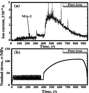
Figure 1 shows (a) the hydrogen desorption spectrum and (b) the corresponding stress-strain curve of a hydrogen-charged pure iron specimen subjected to tensile stress at a strain rate of 4.2 x 10⁻⁴/s until fracture. Hydrogen desorption was small under elastic deformation. In contrast, it increased rapidly at the strain beyond the proof stress when plastic deformation began, reached its maximum, and then decreased gradually with increasing plastic strain.
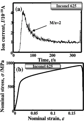
Figure 2 shows (a) the hydrogen desorption spectrum and (b) the corresponding stress-strain curve of a hydrogen-charged Inconel 625 specimen subjected to tensile stress at a strain rate of 4.2 x 10⁻⁴/s until fracture. The hydrogen desorption behavior was similar to that of the pure iron specimen. It was markedly small under elastic deformation. In contrast, it increased rapidly at the strain beyond the proof stress when plastic deformation began, reached its maximum, decreased gradually as plastic strain increased, and then a sharp peak appeared at fracture.
To examine more closely the effect of elastic/plastic deformation on hydrogen desorption behavior, cyclic elastic stress was applied prior to the final fracture. Figure 3 shows (a) the hydrogen desorption spectrum and (b) the corresponding stress-time curve of a hydrogen-charged pure iron specimen subjected to 30 elastic stress cycles between 20 and 40 MPa, followed by the application of tensile stress at a strain rate of 4.2 x 10⁻⁴/s until fracture. Hydrogen desorption was small under cyclic elastic stress. It increased rapidly at the strain beyond the proof stress when plastic deformation began, reached its maximum, and then decreased gradually as plastic strain increased.
Nom
inal str
ess,
σ
/MP
a
0 0.3 0.4
0 100
50 150
0.1 0.2
Nominal strain,
ε
Pure iron Pure iron(b)
0 100 200 300 400 500 600 700 0 5 10
Time, t/s
Ion
cu
rren
t,
I/
10
-11
A
(a)
Pure ironPure ironM/z=2
Nom
inal str
ess,
σ
/MP
a
0 0.3 0.4
0 100
50 150
0.1 0.2
Nominal strain,
ε
Pure iron Pure iron(b)
0 100 200 300 400 500 600 700 0 5 10
Time, t/s
Ion
cu
rren
t,
I/
10
-11
A
(a)
Pure ironPure ironM/z=2
Figure 1: Correlation between (a) hydrogen desorption spectrum and (b) stress-strain curve of a hydrogen-charged pure iron.
0 100 200 300
0 2 4 1 3
Time, t/s
Io
n
cu
rr
en
t,
I
/1
0
-10
A
Inconel 625Inconel 625
(a)
N
o
m
in
a
l st
r
ess,
σ
/M
Pa
0 0.05 0.1 0.15
0 500 1000
Nominal strain,
ε
Inconel 625 Inconel 625
(b)
M/z=2
0 100 200 300
0 2 4 1 3
Time, t/s
Io
n
cu
rr
en
t,
I
/1
0
-10
A
Inconel 625Inconel 625
(a)
N
o
m
in
a
l st
r
ess,
σ
/M
Pa
M/z=20 0.05 0.1 0.15
0 500 1000
Nominal strain
Inconel 625 Inconel 625(b)
,
ε
100 200 300 400 500 600 700 800 900 0 100 50 150 0
(b)
N o m in a l stre ss,σ
/M P a Pure iron Pure iron 0 2 40 100 200 300 400 500 600 700 800 900 3 1 5
(a)
Time, t/s Io n current , I/ 10 -1 1A Pure iron Pure iron M/z=2 Time, t/s100 200 300 400 500 600 700 800 900 0 100 50 150 0
(b)
N o m in a l stre ss,σ
/M P a Pure iron Pure iron 0 2 40 100 200 300 400 500 600 700 800 900 3 1 5
(a)
Time, t/s Io n current , I/ 10 -1 1A Pure iron Pure iron M/z=2 Time, t/sFigure 3: Correlation between (a) hydrogen desorption spectrum and (b) stress-time curve of a hydrogen-charged pure iron subjected to cyclic elastic stress and subsequent tensile stress until failure.
0 500 1000
0 1 2 3 Io n c u rr en t, I /1 0 -1 0 A Time, t/s Inconel 625 Inconel 625
(a)
N o m in a l st re ss ,σ
/M P a 1500 500 1000 0 0 500 1000 Time, t/s Inconel 625 Inconel 625(b)
M/z=20 500 1000
0 1 2 3 Io n c u rr en t, I /1 0 -1 0 A Time, t/s Inconel 625 Inconel 625
(a)
N o m in a l st re ss ,σ
/M P a 1500 500 1000 0 0 500 1000 Time, t/s Inconel 625 Inconel 625(b)
M/z=2Figure 4: Correlation between (a) hydrogen desorption spectrum and (b) stress-time curve of a hydrogen-charged Inconel 625 subjected to cyclic elastic stress and subsequent tensile stress until failure.
3.2 Strain Rate Dependence of the Amount of Desorbed Hydrogen
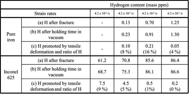
fracture at various strain rates, (b) after holding in the vacuum chamber without tensile stress for a duration corresponding to the time to fracture, and (c) the amount of desorbed hydrogen ((b)-(a)) promoted by tensile deformation until fracture and the ratio of desorbed hydrogen to the initial content. The percentages in parentheses in Table 1 are the ratio of the desorbed hydrogen content to the initial hydrogen content. For pure iron, the largest amount of desorbed hydrogen promoted by tensile stress was 0.21 mass ppm, i.e., 16% of the initial hydrogen content, when the specimen was deformed at a strain rate of 4.2 x 10⁻⁴/s. In contrast, the amount of desorbed hydrogen promoted by tensile stress increased with a decreasing strain rate for Inconel 625 and was 9% of the initial hydrogen content when the specimen was deformed at a strain rate of 4.2 x 10 -6
/s. For both specimens, the amount of desorbed hydrogen promoted by tensile deformation depended on the stain rate.
Table 1: Hydrogen contents of pure iron and Inconel 625 (a) after tensile failure at various strain rates, (b) after holding in the vacuum chamber without undergoing tensile test for the time corresponding to the time to
fracture, and (c) desorbed hydrogen contents ((b)-(a)) promoted by tensile deformation until failure and the ratio of desorbed hydrogen to the initial content.
7.5 (9 %) 68.7 61.2
-4.2 x 10⁻⁶/s 4.2 x 10⁻⁵/s 4.2 x 10⁻⁴/s 4.2 x 10⁻³/s Strain rates 0.2 (0 %) 0.5 (1%) 4.5 (5 %) (c) H promoted by tensile
deformation and ratio of H
86.6 86.1
75.3 (b) H after holding time in
vacuum
86.4 85.6
70.8 (a) H after fracture
Inconel 625 Pure iron 0.05 (4 %) 0.21 (16 %) 0.10 (8 %) (c) H promoted by tensile
deformation and ratio of H (b) H after holding time in
vacuum (a) H after fracture
1.30 0.91 0.23 1.25 0.70 0.13
Hydrogen content (mass ppm)
4 DISCUSSION
4.1 Relationship Between Hydrogen Transport by Moving Dislocations and Stress-Strain Curve
Hydrogen desorption behavior during elastic deformation is discussed first. As shown in Figs. 2 and 4, hydrogen desorption during elastic deformation was not detected for Inconel 625 with its high proof stress and distinct boundary between elastic and plastic deformation. This behavior implies that dislocations do not move in Inconel 625, so hydrogen transport by moving dislocations does not occur. In contrast, for pure iron with its low proof stress and without an obvious yield point, slight hydrogen desorption during elastic deformation was detected as shown in Figs. 1 and 3. This is because the pinning of dislocations in pure iron does not occur, allowing mobile dislocations on slip lines to move with hydrogen and to transport hydrogen to the specimen surface in spite of the elastic stress.
Cx = CL exp ( EB /kBT ) (1) where Cx is the concentration of hydrogen by atomic ratio at trapping sites, CL is the concentration of solid
solution hydrogen, kB is the Boltzmann constant, T is absolute temperature, and EB is the binding energy
between trapping sites and hydrogen. Equation (1) indicates that the concentration of hydrogen around dislocations depends on EB and T, when the initial hydrogen concentration is constant. As tensile tests were
conducted in this study at a constant temperature, the concentration of hydrogen around dislocations depends on only EB. In α-iron with a bcc lattice, the interaction between edge dislocations with a hydrostatic stress
field and hydrogen is generally large, and the binding energy between edge dislocations and hydrogen is reported to be 58 kJ/mol [13]. In contrast, the interaction between screw dislocations without a hydrostatic stress field and hydrogen is smaller than that of edge dislocations. Thus, the binding energy between screw dislocations and hydrogen is reported to be 19 kJ/mol [13] and 20-30 kJ/mol [14]. Although the binding energy values differ among researchers, there is agreement that the binding energy between edge dislocations and hydrogen is larger than that of screw dislocations. Accordingly, the concentration of hydrogen around edge dislocations is greater than that around screw dislocations as expressed in equation (1), which means that a Cottrell atmosphere of hydrogen easily forms around edge dislocations, and a high concentration of hydrogen forms at the core of edge dislocations in bcc metals.
The binding energy between dislocations and hydrogen is 8.7-19.3 kJ/mol [15] in pure nickel with an fcc lattice. This level of binding energy is much lower than that of bcc metals and it suggests that the concentration of hydrogen around dislocations in fcc metals is smaller than that for bcc metals. This means that the interaction between hydrogen and dislocations in fcc metals is little connected with hydrogen diffusion. These findings show the difference in the interaction between dislocations and hydrogen in bcc metals and that between dislocations and hydrogen in fcc metals.
Next, we will consider the relationship between hydrogen transport by moving dislocations and the stress-strain curve. In general, edge dislocation mobility is larger than that of screw dislocations at the beginning of plastic deformation in every crystal structure under room temperature. Therefore, edge dislocations with high mobility move on the slip plane and reach the specimen surface first, and then screw dislocations play a main role in subsequent plastic deformation. This difference in mobility between edge dislocations and screw dislocations corresponds to the hydrogen desorption spectra obtained in the present study. The sharp increase in hydrogen desorption when plastic deformation begins implies that much hydrogen is transported to the specimen surface by edge dislocations having large binding energy with hydrogen. The dislocation density is low and there are few obstacles on the slip plane at the onset of plastic deformation, so dislocations can move straight and over a long distance on the slip plane of the primary slip system. The decrease in hydrogen desorption during subsequent plastic deformation corresponds to the decrease in hydrogen transport by screw dislocations. This is because the binding energy between screw dislocations and hydrogen is smaller, i.e., the Cottrell atmosphere of hydrogen is smaller around screw dislocations. In addition, the number of dislocations moving over a long distance to the specimen surface decreases, since their intersections tend to cause cross slips, resulting in the formation of a tangled cell structure, and pile-ups at grain boundaries. Furthermore, the density of vacancies during subsequent plastic deformation is greater than that at the beginning of plastic deformation. Since vacancies are more stable trapping sites for hydrogen than dislocations [9], hydrogen tends to be trapped at vacancies in the specimen and therefore the amount of hydrogen transported by moving dislocations may decrease.
4.2 Relationship Between Hydrogen Transported by Moving Dislocations and Strain Rate
The strain rate dependence of hydrogen transport by moving dislocations can be seen in the results shown Table 1. For pure iron, the largest amount of desorbed hydrogen promoted by tensile stress was 0.21 mass ppm, i.e., 16% of the initial hydrogen content, when the metal was deformed at a strain rate of 4.2 x 10 -4
/s. This result indicates that the interaction between dislocations and hydrogen had a sufficient effect at this strain rate. The reason for the decrease in the amount of hydrogen transported by moving dislocations at a strain rate of 4.2 x 10⁻³/s, i.e., ten times higher than 4.2 x 10⁻⁴/s, is that the dislocation velocity was much higher than the hydrogen diffusion rate. As a result, only a little hydrogen interacted with dislocations. The reason for the decrease in the amount of hydrogen transported by moving dislocations at a strain rate of 4.2 x 10⁻⁵/s, i.e., one-tenth higher than 4.2 x 10⁻⁴/s, is that the hydrogen diffusion rate was much higher than the dislocation velocity. Therefore, hydrogen self-diffused to the specimen surface by a thermally activated process before it was transported by dislocations.
velocity at a strain rate of 4.2 x 10⁻⁴/s for Inconel 625. It is expected that the interaction between dislocations and hydrogen can occur when the strain rate is three orders of magnitude lower than 4.2 x 10⁻⁴/s. The amount of desorbed hydrogen promoted by tensile stress was 1%, 5% and 9% of the initial hydrogen content at strain rates of 4.2 x 10⁻⁴/s, 4.2 x 10⁻⁵/s and 4.2 x 10⁻⁶/s, respectively, as shown in Table 1. These experimental results concerning the strain rate dependence of hydrogen desorption agree well with the expected interaction between dislocations and hydrogen velocities. Hydrogen desorption increased when the average dislocation velocity decreased. As discussed in the preceding section, three reasons can be considered for the higher ratio of hydrogen transport by moving dislocations seen for pure iron (16%) than for Inconel 625. (i) The binding energy between dislocations and hydrogen is greater in bcc metals than in fcc metals. (ii) Hydrogen stable sites in iron with a bcc lattice are tetrahedral sites on the slip plane (112) of bcc metals, allowing hydrogen to be dragged easily by moving dislocations. (iii) Dislocations can move over a long distance in pure iron.
5 CONCLUSIONS
The desorption dynamic behavior of weakly trapped diffusive hydrogen, causing a reduction of fracture strain, has been analyzed in situ during deformation at room temperature using a pure iron as a bcc metal and an Inconel 625 alloy as an fcc metal. The results obtained regarding the effect of elastic/plastic deformation on hydrogen desorption behavior can be summarized as follows.
(1) Hydrogen desorption seldom increases under elastic deformation. In contrast, it increases rapidly after the proof stress when plastic deformation begins, reaches its maximum, and then decreases gradually with increasing applied strain. This desorption behavior is probably closely related to moving dislocations during plastic deformation and depends on the dislocation type such as edge or screw dislocations and dislocation mobility.
(2) The amount of desorbed hydrogen during tensile deformation differs at different strain rates. The largest amount of desorbed hydrogen promoted by tensile stress was observed when pure iron with a high hydrogen diffusion coefficient was deformed at a strain rate of 4.2 x 10⁻⁴/s. It was 16% of the initial hydrogen content. The amount of desorbed hydrogen decreased at strain rates of 4.2 x 10⁻⁵/s and 4.2 x 10⁻³/s. In contrast, the amount of desorbed hydrogen increased with a decreasing strain rate for Inconel 625 with a lower hydrogen diffusion coefficient. The largest amount of desorbed hydrogen promoted by tensile stress was 9% of the initial hydrogen content when Inconel 625 was deformed at a strain rate of 4.2 x 10⁻⁶/s. This difference in the amount of desorbed hydrogen is probably related to the amount of hydrogen that can move with moving dislocations.
6 ACKNOWLEDGEMENTS
The present study was supported by a Grant-in-Aid for Science Research B (No. 18360336).
7 REFERENCES
[1] TAKAI, K., WATANUKI, R., “Hydrogenintrapping states innocuous to environmental degradationof high-strength steels”, ISIJ International, v. 43, n. 4, pp. 520-526, 2003.
[2] TAKAI, K., CHIBA, Y., NOGUCHI, K., NOZUE, A., “Visualization of the hydrogen desorption process from ferrite, pearlite, and graphite by secondary ion mass spectrometry”, Metallurgical Materials
Transactions A, v. 33, n. 8 pp. 2659-2665, August 2002.
[3] ORIANI, R.A., JOSEPHIC, P.H., “Equilibrium aspects of hydrogen-induced cracking of steels”, Acta
Metallurgica, v. 22, n. 9, pp. 1065-1074, 1974.
[4] BIRNBAUM, H.K., SOFRONIS, P., “Hydrogen-enhanced localized plasticity-a mechanism for hydrogen-related fracture”, Materials Science and EngineeringA, v. 176, n. 1–2, pp. 191-202, 1994. [5] NAGUMO, M., “Hydrogen related failure of steels - A new aspect”, Materials Science and Technology,
v. 20, n. 8, pp. 940-950, 2004.
[7] TAKAI, K., SHODA, H., SUZUKI, H., NAGUMO, M., “Lattice defects dominating hydrogen-related failure of metals”, Acta Metallurgica, v. 56, n. 18, pp. 5158-5167, October 2008.
[8] SAKAKI, K., KAWASE, T., HIRATO, M., MIZUNO, M., ARAKI, H., SHIRAI, Y., NAGUMO, M., “The effect of hydrogen on vacancy generation in iron by plastic deformation”, Scripta Materialia, v. 55, n. 11, pp. 1031-1034, 2006.
[9] TATEYAMA, Y., OHONO, T., “Atomic-scale effects of hydrogen in iron toward hydrogen embrittlement: Ab-initio study”, Iron Steel Institute Japan, v. 43, n. 4, pp. 573-578, 2003.
[10] LOUTHAN, M.R., CASKEY, G.R., DONOVAN, J.A., RAWL, D.E., “Hydrogen embrittlement of metals”, Materials Science and Engineering, v. 10, pp. 357-368, 1972.
[11] DONOVAN, J.A., “Accelerated evolution of hydrogen from metals during plastic deformation”,
Metallurgical Materials Transactions A, v. 7, pp. 1677-1683, 1975.
[12] BRASS, A.M., CHENE, J., “Influence of deformation on the hydrogen behavior in iron and nickel base alloys: A review of experimental data”, Materials Science Engineering A, v. 242, n. 1 – 2, pp. 210 - 221, February 1998.
[13] HWANG, C., BERNSTEIN, I.M., “Dislocation transport of hydrogen in iron single crystals”, Acta
Metallurgica, v. 34, n. 6, pp. 1001-1010, June 1986.
[14] HIRTH, J.P., “Effects of hydrogen on the properties of iron and steel”, Metallurgical Transactions A, v. 11, pp. 861, 1980.