*e-mail: [email protected]
Second Phase Precipitation in Ultrafine-grained Ferrite Steel
Juno Gallegoa*, Alessandro Roger Rodriguesb, Cleiton Lázaro Fazolo de Assisb, Luciana Montanarib
aDepartment of Mechanical Engineering, São Paulo State University – UNESP, Av. Brasil Centro, 56, CEP 15385-000 Ilha Solteira, SP, Brazil bDepartment of Mechanical Engineering, University of São Paulo – USP, Av. Trabalhador São-carlense, 400, CEP 13566-590 São Carlos, SP, Brazil
Received: September 22, 2013; Revised: November 20, 2013
Grain size reinement is one of the most eficient strengthening mechanisms applied to modern High-Strength Low-Alloy steels (HSLA) because yield strength and toughness are both improved. This paper discusses the distribution of carbides by using transmission electron microscopy (TEM) in a low-carbon steel with ultraine grained (UFG) ferrite. Fine cementite particles were formed during water quenching due to the auto-tempering of highly distorted martensite. Other ine particles observed under the same condition were nucleated due to the presence of carbide formers such as niobium, titanium and vanadium. TEM analysis showed that cementite particles underwent Ostwald ripening during warm rolling but they were still able to inhibit ferrite grain growth, which was maintained 1µm size approximately.
Keywords: ultrafine-grained steel, thermomechanical processing, carbide/carbonitride precipitation, ferrite, microstructure, transmission electron microscopy, electron diffraction
1. Introduction
According to Hall-Petch model the decrease in the ferrite grain size implies improved yield strength of low-carbon structural steels. This microstructure-properties behavior has led to the development of new microalloying compositions and thermomechanical routes aiming at the industrial manufacture of steels with ultraine grains1,2. However, the control of the grain growth through particles distribution, with appropriate size and volume fraction, became strictly necessary3-6.
Iron or other metallic elements, such as niobium (Nb), titanium (Ti) and vanadium (V), combined with carbon are able to generate cementite and others carbides or carbonitrides in HSLA microalloyed steels. Nb, Ti and V tend to form complex and more thermodynamically stable compounds than iron carbides allowing the grain boundaries pinning at higher processing temperatures where niobium or titanium carbides or carbonitrides present limited solubility in austenite7. However, a distribution of ine cementite or carbonitride particles could inhibit the ferrite grain growth at lower temperatures8,9, where recrystallization is quite restricted. The role of this ine dispersion particles on the formation of ultraine grains has been few explored by transmission electron microscopy (TEM). In the present paper both dispersions of cementite and carbonitride, formed during different stages of thermomechanical processing, were analyzed and its effect to obtain an ultraine ferrite microstructure based on commercial low-carbon steel is discussed.
2. Material and Methods
Samples of commercial low-carbon steel with 25 × 25 × 100 mm size were machined from rolled plates. Their chemical composition is speciied in Table 1. The specimens were austenitized at 900 °C for 30 min following water-cooled under agitation at room temperature. In that austenitizing temperature no signiicative grain growth was noted and the cementite was completely dissolved. After quenching, the workpieces were reheated at 740 °C for 12 min and rolled in three passes to reduce 20% the thickness in each pass (50% total deformation). Rolled samples were briely reheated at temperature for 6 min between each pass to minimize the temperature drop. Finally, the specimens were air-cooled at the end of warm thermomechanical processing.
Gallego et al.
3. Results and Discussion
3.1.
Microstructure after quenching
The water cooling of the specimens generated a complex acicular microstructure, composed mainly by bainite and martensite. The visibility of grain boundaries/interfaces in some regions of Figure 1a is sometimes very poor in bright ield (BF) contrast due to the presence of bend contours and small angular misit between neighboring regions. Martensite/bainite was normally disposed in bundles of laths which may form larger blocks. Acicular widths have ranged between 200 and 500 nm and their length exceeding often 1 µm depended on respective block size. However, sub regions inside each lath were separated by dense dislocation arrangements that could be normally distinguished in TEM micrographs. The crystallographic misorientation among these sub regions must be small (< 5°), but it is enough to generate ring-type SAED patterns where some texture effects can be observed with stronger ferritic spots occupying well-deined arc sectors, Figure 1b. Key diagram presented in Figure 1c indicates that stronger cementite relections are very close to ferrite relections, bringing as a result some dificult to distinguish them by SAED analysis. Some sparse cementite relections are visible in SAED pattern and were also identiied in Figure 1c. Such electron diffraction behavior was associated to the “fragmentation” of the TEM image contrast, especially in dark ield (DF) mode due to very small located differences in diffraction orientation. Similar microstructures have been reported in other studies on UFG steels obtained by either martensite formation9,12 or severe plastic deformation such as Equal Channel Angular Pressing (ECAP)13-15 or Warm Torsion
Testing8,16.
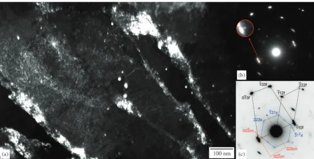
Austenitizing at 900 °C has completely dissolved the previous cementite because coarse carbide particles were not found. Figure 2a shows the formation of elongated ine cementite particles inside of a martensite lath, quite similar as reported by Furuhara and co-workers17. The SAED pattern in Figure 2b presents a zone axis near to [001]f orientation, being also observed some weak and streaked relections coming from second phase particles that precipitated in two orthogonal variants. Coarse globular inclusions, identiied as manganese sulide, were observed in few regions. Rare
islands of retained austenite and twin martensite were also observed in thin foils.
Indexation of matrix-precipitate orientation relationship (OR), Figure 2c, has showed be consistent with Bagaryatski18,19 OR for bainitic ferrite and cementite, not presenting good itting with Jack20,21 OR for bainitic ferrite
and epsilon carbide. In fact, ε-carbide were not found in the investigated steel probably due to its low carbon content22. The zone axis of variant I is close to [113]c of cementite particles, being variant II obtained by 90° rotation around [001]f matrix axis zone. These ine elongated cementite particles (50-150 nm long, 10-25 nm wide) were formed during quenching (auto-tempering mechanism) probably favored by the high temperature of martensite formation Ms (low hardenability) and local carbon super saturation23.
Rounded 5-25 nm size particles heterogeneously distributed between martensite/bainite laths were also observed after water quenching, as illustrated in DF TEM micrograph from Figure 3a. The respective SAED pattern is presented in Figure 3b which shows in detail the diffracted spot selected by the objective aperture, positioned close to a relection of matrix. Some weak and diffuse diffraction spots of magnetite, resulting from slightly sample oxidation, are also observed in the pattern and are indicated as {hkl} x relections. Its indexing is indicated in the key diagram of Figure 3c, that suggest a zone axis comprised between [110]f and [331]f (tilt of 13.2 degrees) due to several laths have been selected by SAD aperture. Considering the TEM camera-length calibration done during experimental it was possible estimate the interplanar spacing of the interest relection in 0.219 nm. The interplanar spacing of (201) c planes from cementite corresponds 0.221 nm, showing a good approximation. However, it should not be found {201}c cementite planes parallel to {110}f ferrite planes according to Bagaryatski18,19 OR which means that relection came from another compound.
The distribution and morphology of the particles shown in Figure 3a suggest they are niobium/titanium carbonitrides formed in austenite during high temperature industrial rolling and that were not dissolved during soaking before quenching. The steel used in this research contains signiicant amounts of niobium, titanium and vanadium (Table 1) able to generate a signiicant volume fraction of carbonitrides,
Table 1. Chemical composition of the low-carbon steel (% weight).
C Mn Si Al Cr Ni Nb V Ti
0.16 1.49 0.27 0.046 0.276 0.008 0.048 0.044 0.016
Table 2. Crystallographic parameters of the investigated phases10.
CIF # Phase System (IT number) a (nm) b (nm) c (nm)
52258 Ferrite Cubic (229) 0.2866 -
-16593 Cementite Orthorhombic (62) 0.5090 0.6748 0.4523
44354 ε carbide Hexagonal (182) 0.4767 - 0.4354
618386 (Nb,Ti)(C,N) Cubic (225) 0.4377 -
-26410 Magnetite Cubic (227) 0.8394 -
theoretically estimated in 1.58 × 10⁻³ by stoichiometry. In fact, the result of interplanar spacing (0.219 nm) for selected spot in Figure 3c presents an excellent itting with the {002} cn relection calculated for (Nb,Ti)(C,N), Table 2. In same SAED pattern other weak spots are related with carbonitride, whose corresponding zone axis was found near to [100] cn. It is known that precipitation of carbonitrides in ferrite must present the Baker-Nutting7 OR, what was not observed with that rounded coarse kind of particles. Thus, they were nucleated in austenite during thermomechanical processing applied to steel6.
Another particle distribution, iner than reported earlier, was observed after quenching of steel. Dark ield micrograph in Figure 4a presents precipitates with 3 to 10 nm size inside a bainite/martensite lath and its respective SAED pattern, Figure 4b. It is possible observe in Figure 4c that electron diffraction pattern is composed by strong well-deined spots from [3–71]f matrix orientation. Indexing of relections coming from ine carbonitride distribution shown that zone axis are close to [011]cn, being the selected spot used to DF contrast consistent with electron diffraction of (200)cn cubic (Nb,Ti)(C,N), Table 2. The lack of any Baker-Nutting7
Figure 1. Thin foil TEM BF micrograph obtained after austenitizing at 900 °C/30 min and water quenching. Blocks and laths of martensite/
bainite are showing in (a) with its respective polycrystalline electron diffraction pattern in (b). Letters f and c identify respectively ferrite and cementite relections in the key diagram in (c).
Gallego et al.
orientation relationship with ferrite in SAED analysis conirms that these ine particles were nucleated in austenite, probably on dislocations generated during industrial rolling of the investigated steel. Such ine carbonitride distribution would be able to inhibit/retard ferrite grain growth.
3.2.
Microstructure after warm
thermomechanical processing
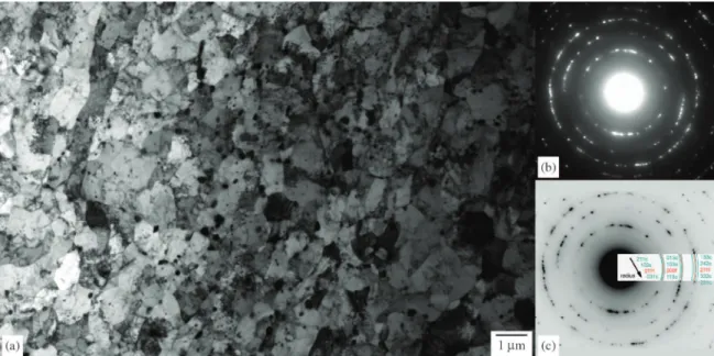
The thermomechanical processing applied to the low-carbon steel generated effectively ultraine ferrite grains, as shows BF TEM micrograph of the Figure 5a. After the
warm rolling under total deformation of 50% at 740 °C, the partial recrystallization of martensite/bainite structure and consequent ultraine ferrite grain formation took place. So, Low and High Angle Grain Boundaries (LAGB/HAGB) of ferrite grains could be formed and their existence was proven due to ring-type SAED patterns observed in Figure 5b. Most of stronger relections of cementite are really close to the low-index ferrite planes, becoming hard their identiication in Figure 5c. Cementite particles are clearly identiied by contrast, especially those nucleated on ferrite grain boundaries. Dislocation arrays have contributed
Figure 3. TEM micrograph showing in (a) dark ield contrast taken from a {002}cn relection of undissolved globular (Nb,Ti) carbonitrides
and respective electron diffraction pattern in (b). Key diagram in (c) shows that particles were formed in austenite and also presents some magnetite (x) relections.
Figure 4. TEM micrograph showing in (a) dark ield contrast taken from a {002}cn relection of iner (Nb,Ti) carbonitrides and respective electron diffraction pattern in (b). Key diagram in (c) suggests that particles were also formed in austenite together some oxidation of
iron matrix.
to nucleation of cementite inside UFG ferrite. Although dislocation density in ferrite grains has not been determined, the occurrence of this kind of defect does not seem to fully annealed condition of the investigated steel.
Previous structure of the as-quenched low-carbon steel presented a complex microstructure, comprised morphologically by laths or plates of martensite/bainite grouped in packets, blocks or sheaves17,18,22-25. According to Tsuji et al.12 the effect of high-angle boundaries combined with complicated morphology of packets and blocks is able to provoke a constraint effect during warm plastic deformation. As a consequence, inhomogeneous deformation applied on a highly distorted martensite/bainite structure should increase crystallographic misorientation locally, promoting recovery and formation of new UFG ferrite during short warm annealing12.
The BF TEM image in Figure 6a shows ferrite grains with equiaxed and acicular morphologies, as well as rounded particles of cementite that are normally found dispersed on the grain boundaries. Dislocations were observed inside ferrite grains and their visibility oftentimes was impaired due to local changes of diffraction and presence of bend contours. Carbide coarsening (Ostwald ripening) have been favored during warm thermomechanical processing due to available of carbon in solid solution and its mobility improved by different “ways” (dislocations, LAGB/HAGB interfaces, grain boundaries)7,26. The SAED pattern in Figure 6b, extracted from encircled region indicated in the BF micrograph, shows a complex orientation, in which zone axis of ferrite varies between [100]f and [101]f as resulted from partial recrystallization. According to Figure 6c some cementite particles have [201–]c orientation, whose parallelism with [100]f is consistent with ferrite-cementite OR described by Zhang and Kelly26 in their investigation on tempered martensite (Equation 1). Other relections of cementite were identiied but they did not present any
speciic OR, probably due to its loss of orientation with ferrite occurred during warm annealing.
(101)f // (103)c and [131]f // [010]c (1)
Fine cementite lamellae (7-13 nm thick) were rarely observed in the thin foil samples after thermomechanical processing, Figure 7a. Their existence suggests that a quickly diffusional transformation took place during warm treatment. Dark-ield contrast was obtained from a [2–2–1–]c cementite relection provided from a slightly oxidized pearlitic region, Figures 7b and c. Ferrite lamellae orientation have changed between [1–1–0]f and [2–1–0]f (tilt of 18.4 degrees) while cementite zone axis is close to [1–02]c.
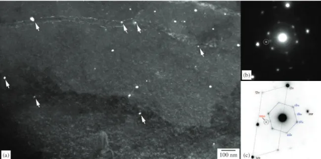
Such as observed after quenching, rounded precipitates ranging between 5 and 25 nm were also identiied in the ferrite grains formed during warm thermomechanical processing as shown by arrows in Figure 8a. Although it was not possible found an orientation relationships of that kind of particles with ferrite in Figure 8b, their morphology and dispersion are rather similar to niobium/titanium carbonitrides formed in austenite reported earlier. In fact, they should have been preserved because both dissolution and coarsening of those particles are negligible under condition wherein warm processing was performed6,7. The selected spot used to generate DF contrast, indicated in Figure 8c, is consistent with a (200)cn relection of (Nb,Ti) (C,N) presented in Table 2.
It has been well established the role of a dispersion of ine stable particles on the grain growth, also known as pinning effect2,4. The size (D) of the pinned grain due to a distribution of particles with size (d) and volume fraction (f) can be mathematically described by Equation (2)4.
=0.17⋅d
D
f (2)
Figure 5. Thin foil TEM micrograph obtained after warm thermomechanical processing. Typical panoramic view showing formation of
Gallego et al.
Figure 9a shows a typical cementite precipitation in ferrite observed by TEM. Quantitative analysis of cementite size particles carried out on 346 particles resulted in the histogram presented in Figure 9b. It was observed that modal size is approximately 70 nm while mean particle size of cementite was estimated 114.7 nm with standard deviation of 45.5 nm. Considering that all carbon has been used to form precipitates, it was calculated that niobium, titanium, vanadium and iron generated a total volume fraction corresponding to 0.023. Applying these results to Equation 2, reined ferrite grain obtained is 0.85 µm, which
is very close to the grain size measured experimentally (0.9 µm)27. Definitively ferrite grain size refinement obtained after proposed thermomechanical route could be associated to improved properties of the machined steel reported earlier28.
4. Conclusions
The observation of thin foils by transmission electron microscopy revealed that there was formation of fine cementite platelets (50-150 nm long, 10-25 nm wide) during
Figure 6. TEM BF micrograph showing in (a) evidences of partial recrystallization in deformed bainite/martensite laths. Electron diffraction
pattern of the encircled area presenting complex ferrite orientation in (b) and its key diagram in (c) shows a cementite orientation close to [201–]c in a region with ferrite zone axis between [100]f and [101]f.
Figure 7. TEM micrograph showing in (a) dark ield contrast of cementite lamellae taken from a {221}c relection and respective electron diffraction pattern in (b). Key diagram in (c) indicates a cementite orientation close to [1–02]c in a region with ferrite zone axis between [1–1–0]f and [2–1–0]f.
water quenching due to the auto-tempering of the low-carbon martensite. The warm thermomechanical processing applied to obtain an UFG microstructure contributed to the coarsening of rounded cementite particles but, together with a ine (Nb,Ti)(C,N) distribution formed in austenite during industrial processing of the investigated steel, were still able to inhibit ferrite grain growth that were formed after recrystallization. The experimental determination of the mean size (115 nm) and volume fraction (0.023) of cementite and carbonitrides have shown good itting with
0.9 µm ferrite grain size that was predicted by a pinning model for grain growth.
Acknowledgements
The authors would like to thank the Brazilian agencies FAPESP, CNPq and CAPES for their inancial support provided for this research and the Laboratory of Electron Microscopy at the Federal University of São Carlos (LCE/ DEMa/UFSCar – Brazil) for allowing us to use their electron microscopy facilities.
Figure 8. TEM micrograph showing in (a) dark ield contrast of ine carbonitrides, indicated by white arrows, on UFG ferrite boundaries.
Electron diffraction pattern in (b) and its key diagram in (c) suggest that particles were nucleated in austenite and some oxidation occurred
on sample’s surface.
Gallego et al.
References
1. Weng Y. Ultra-Fine Grained Steels. New York: Spring Berlin
Heidelberg; 2009.
2. Song R, Ponge D, Raabe D, Speer JG and Matlock DK.
Overview of processing, microstructure and mechanical properties of ultrafine grained BCC steels. Materials Science and Engineering: A. 2006; 441:1-17. http://dx.doi.
org/10.1016/j.msea.2006.08.095
3. Hellmann P and Hillert M. On the effect of second-phase
particles on grain growth. Scandinavian Journal of Metallurgy.
1975; 4(5):211-219.
4. Manohar PA, Ferry M and Chandra T. Five decades of the Zener Equation. ISIJ International. 1998; 38(9):913-924. http:// dx.doi.org/10.2355/isijinternational.38.913
5. Humphreys FJ. A uniied theory of recovery, recrystallization
and grain growth, based on the stability and growth of cellular microstructures - the effect of second-phase particles.
Acta Materialia. 1997; 45(12):5031-5039. http://dx.doi. org/10.1016/S1359-6454(97)00173-0
6. Kestenbach H-J, Campos SS, Gallego J and Morales EV.
Discussion of Precipitation behavior and its effect on strengthening of an HSLA-Nb/Ti steel. Metallurgical and Materials Transactions A. 2003; 34A(4):1013-1017. http://
dx.doi.org/10.1007/s11661-003-0231-9
7. Gladman T. The Physical Metallurgy of Microalloyed Steels.
London: Institute of Materials; 1997.
8. Gallego J, Jorge AM Jr and Balancin O. Microstructure evolution during warm deformation of low carbon steel with dispersed cementite. Materials Science Forum. 2007; 558:505-510. http://dx.doi.org/10.4028/www.scientiic.net/
MSF.558-559.505
9. Ueji R, Tsuji N, MinaminoY and Koizumi Y. Ultragrain refinement of plain low carbon steel by cold-rolling and
annealing of martensite. Acta Materialia. 2002;
50(16):4177-4189. http://dx.doi.org/10.1016/S1359-6454(02)00260-4
10. Belsky A, Hellenbrandt M, Karen VL and Luksch P.
New developments in the Inorganic Crystal Structure Database (ICSD): accessibility in support of materials research and design. Acta Crystallographica B. 2002;
58(1):364-369. PMid:12037357. http://dx.doi.org/10.1107/ S0108768102006948
11. Imagetool Freeware. Available from: <http://compdent. uthscsa.edu/dig/itdesc.html>. Access in: 10/07/2013.
12. Tsuji N, Ueji R, Minamino Y and Saito Y. A new and
simple process to obtain nano-structured bulk low-carbon steel with superior mechanical property. Scripta Materialia.
2002; 46(4):305-310. http://dx.doi.org/10.1016/S1359-6462(01)01243-X
13. Shin DH, Park JJ, Chang SY, Lee YK and Park KT. Ultraine
Grained Low Carbon Steels Fabricated by Equal Channel Angular Pressing: Microstructures and Tensile Properties.
ISIJ International. 2002; 42(12):1490-1496. http://dx.doi.
org/10.2355/isijinternational.42.1490
14. Shin DH, Kim I, Kim J and Park KT. Grain refinement mechanism during ECAPing of a low-carbon steel. Acta
Materialia. 2001; 49(7):1285-1292. http://dx.doi.org/10.1016/
S1359-6454(01)00010-6
15. Dong HS, Chang WS, Jongryoul K, Kyung-Tae P and Wung
YC. Microstructures and mechanical properties of equal-channel angular pressed low carbon steel. Scripta Materialia.
2000; 42(7):695-699. http://dx.doi.org/10.1016/S1359-6462(99)00422-4
16. Calado WR and Barbosa RANM. Ultra grain refinement in a plain carbon steel by means of warm torsion testing.
ISIJ International. 2010, 50(10):1471-1475. http://dx.doi. org/10.2355/isijinternational.50.1471
17. Furuhara T, Kobayashi K and Maki T. Control of cementite precipitation in lath martensite by rapid heating and tempering.
ISIJ International. 2004; 44(11):1937-1944. http://dx.doi.
org/10.2355/isijinternational.44.1937
18. Tu MY, Wang WH and Hsu YF. Crystallographic and
fractographic analysis of upper bainite. Materials Transactions.
2008; 49(3):559-564. http://dx.doi.org/10.2320/matertrans. MRA2007204
19. Shackleton DN and Kelly PM. The crystallography of cementite
precipitation in the bainite transformation. Acta Metallurgica.
1967; 15(6):979-992. http://dx.doi.org/10.1016/0001-6160(67)90263-5
20. Ohmori Y and Tamura I. Epsilon carbide precipitation during tempering of plain carbon martensite. Metallurgical Transactions A. 1992; 23A(10):2737-2751. http://dx.doi.
org/10.1007/BF02651753
21. Andrews KW. The structure of cementite and its relation to ferrite. Acta Metallurgica. 1963; 11(8):939-946. http://dx.doi.
org/10.1016/0001-6160(63)90063-4
22. Bhadeshia HKDH. Bainite in Steels. 2nd ed. London: The
Institute of Materials; 2001.
23. Krauss G and Thompson SW. Ferritic microstructures in continuously cooled low- and ultralow-carbon steels. ISIJ International. 1995; 35(8):937-945. http://dx.doi.org/10.2355/
isijinternational.35.937
24. Morito S, Huang X, Furuhara T, Maki T and Hansen N. The morphology and crystallography of lath martensite in alloy
steels. Acta Materialia. 2006; 54(19):5323-5331. http://dx.doi.
org/10.1016/j.actamat.2006.07.009
25. Furuhara T, Kawata H, Morito S and Maki T. Crystallography
of upper bainite in Fe-Ni-C alloys. Materials Science and Engineering A. 2006; 431(1-2):228-236. http://dx.doi.
org/10.1016/j.msea.2006.06.032
26. Zhang MX and Kelly PM. Crystallography of spheroidite and tempered martensite. Acta Materialia. 1998; 46(11):4081-4091. http://dx.doi.org/10.1016/S1359-6454(98)00046-9
27. Montanari L, Assis CLF, Rodrigues AR, Silva OV Nº and Gallego J. Processamento termomecânico de laminação a morno para reino de grão em um aço 0,16%C. In: Proceedings of the 66th ABM International Congress; 2011; São Paulo, Brazil. São Paulo: ABM; 2011. p. 1599-1606. [in Portuguese].
28. Rodrigues AR, Balancin O, Gallego J, Assis CLF, Matsumoto H, Oliveira FB et al. Surface integrity analysis when milling ultraine-grained steels. Materials Research. 2012;
15(1):125-130 http://dx.doi.org/10.1590/S1516-14392011005000094