A hybrid technique for residual stress analysis through stress
function fitting
Abstract
This work presents a hybrid experimental theoretical tech-nique for residual stresses analysis of mechanical compo-nents. It was used the blind hole technique along with the Electronic Speckle Pattern Interferometry (ESPI) method and Airy stress functions for the determination of the prin-cipal stress components. Displacement information is fitted in order to extract Airy stress function coefficients. The re-sults demonstrate that this technique is of great utility to determine the average principal stress and local stress gra-dients.
Keywords
residual stress, experimental mechanics, stress function, blind hole technique
Marco Antonio Martins Cavaco∗
Mechanical Engineering Department, Federal University of Santa Catarina – UFSC CP:5053, CEP: 88040-970, Florian´opolis, SC – Brazil
Received 30 Nov 2010; In revised form 08 Jun 2011
∗Author email: [email protected]
1 INTRODUCTION
The structural analysis of mechanical components is of vital importance for the industry [2, 4]. In general, Residual stresses are a type of mechanical stress that could compromise the normal life of mechanical systems. This kind of stress is even worse when combined with the local stresses inside the structure. This work studies a different form to quantify residual stresses in structural components.
Residual stresses are, by definition, internal stresses self-equilibrated presented in a free body. Residual stress is normally originated from the manufacturing and improvement pro-cesses and can be tensile or compressive varying from point to point.
This work has the objective to determinate the behavior of the residual stresses components in a previously welded region of piping system [5].
This hybrid technique demonstrates to be very useful to determine the average principal stress and directions along with clean information about the displacement field around the drilled hole.
2 STRESS FUNCTIONS
For plane elastic problems, a function ofr, andθcan be developed which automatically satisfies the equilibrium and compatibility.
If we choose a combination of analytic functions [3, 6, 10] such that
Φ=Φ(0)+Φ(1)+Φ(n)+Φ(∗) (1)
where,
Φ(0)=a0+b0ln(r)+c0r2+d0r2ln(r) (2)
Φ(1)
=(a1r+b1
r +c1r 3
+d1ln(r))⋅{ sinθ
cosθ } (3)
Φ(n) =(anr
n
+bnr
−n
+cnr
2+n
+dnr
2−n
)⋅{ cossinθθ } forn≥2 (4)
Φ(∗)
=a∗θ+b∗r2θ+c∗rθ⋅sinθ+d∗rθ⋅cosθ (5)
One can assume that equation (6) well represents the displacement field around the drilled hole,
Ur(r, θ)=ξr+δr⋅{
sinθ
cosθ +(αr+ωr −1
+γr−3)⋅{ sin 2θ
cos 2θ (6)
where ξ,δ,α,ω and γ, are constants.
If we look at the Kirsh solution [6] for a plate with a circular hole subjected to bi-directional tensile loads.
3 DETERMINATION OF COEFFICIENTS
The displacement data is collected using a circular mesh around the blind hole. Points are distributed in concentric circles using polar coordinates. Data are collected in chunks of 1024 points, located in 8 circles representing a diameter of 8 mm.
The calculation of the principal stresses follows the relationships between the stresses and displacement for biaxial uniform residual stress field around the drilled hole. To obtain the principal stress and direction, it is used the relation [1, 7, 8]
ur(r, θ)=A(r)⋅(σ R
1 −σ
R
2)cos(2θ−2β)+B(r)⋅(σ
R
1 +σ
R
where,
A(r)=−1+υ
2E r⋅[( ro
r ) 4
− 4
1+υ( ro
r ) 2
]
B(r)= 1+υ
2E r⋅( ro
r )
2 (8)
ur is the radial component of the deformation;
σR1,σ
R
2 are the principal stresses; β, is the principal direction;
r,θ are the coordinates of the point that it is being analyzed. Observing equation (6) and (7) one can extract that:
α,δ, are constants;
ξ=(σ1+σ2)rB(r)
ω=(σ1−σ2)⋅[cos(2β)+sin(2β)]⋅rA(r)
γ =(σ1−σ2)⋅[cos(2β)+sin(2β)]⋅r−3A(r) (9)
In order to determine the coefficients of the stress function (6) a non-linear system is created:
G=−[Ur(r, θ)−Ure] (10)
where,
Ur(r, θ) is the equation (6);
Ure is the vector of the radial displacement data from holography.
The solution of the system is found in a least square sense for the coefficients X:
dX=(J‘J)−1⋅J‘G (11)
where,
J is the Jacobian matrix;
dX is the vector of increments.
4 APPLICATION
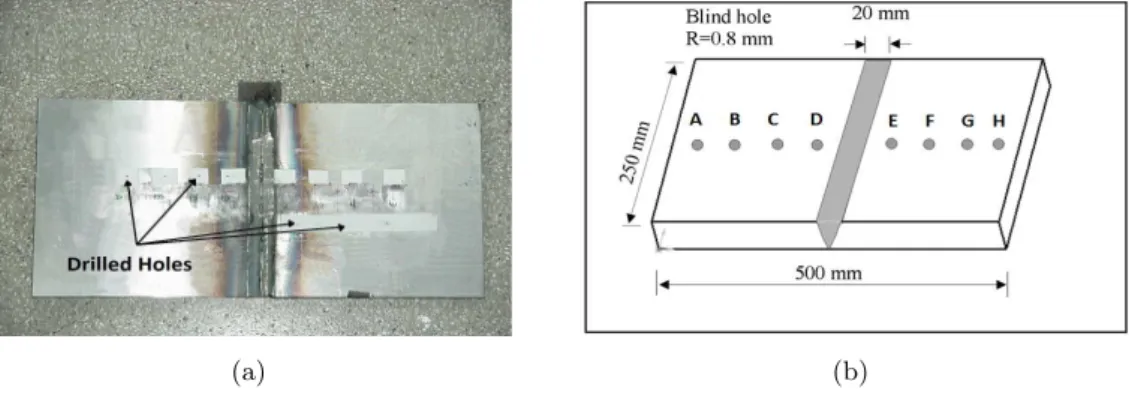
For the demonstration of the method a welded specimen made from 1020 steel was used. A series of 8 holes were located in the middle of the plate, perpendicular to the welding, with a depth of approximately 0.8 mm. Fig. 1 shows a sketch and an actual view of the welded specimen.
1.5mm to 4mm, Fig. 2. The displacements field is obtained after processing the interference im-ages, Fig. 3. The collected data of the radial component of the displacement and its respective polar coordinates are disposed in a matrix and stored in a text file.
(a) (b)
Figure 1 Actual view (a) and sketch (b) of the specimen used for the ESPI blind-hole technique.
Figure 2 Used mesh for collecting data around the drilled hole.
Data from the experimental displacement field is fitted by the stress functions resulting in a equivalent system. The Airy’s Stress Functions coefficients from (1) and (9) are individualized and a smooth displacement field is obtained.
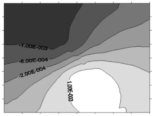
Below, are represented two images that correspond to the displacement field around the drilled hole. The first one was obtained directly by the ESPI technique and the other is calculated by the method of the Airy’s Stress functions. It is clear that the noise presented in the image of Fig. 4 is removed by the application of the stress coefficients in Fig. 5.
Figure 4 Displacement data obtained from
the ESPI technique. Figure 5 Displacement data from thestress functions coefficients.Airy’s
Figure 6 below compares the values of the principal stresses from the ESPI technique and the strain-gage analysis using the RS-200 from Micro-Measurements Group (MM) to the one obtained using the Airy‘s Stress Functions coefficients.
The harmonics technique uses the direct determination ofA(r)andB(r)from equation (7) [11]. The results showed in Fig. (5) for the Stress Functions method have taken into account the blind hole corrections from ASTM E 837-95.
Figure 6 Comparison of difference of
5 CONCLUSIONS
A simple but powerful method is presented for the determination of the residual stresses in mechanical components. This hybrid technique uses a modern method for experimental analysis of stresses and strain using numerical procedures, experimental data and the classical Theory of Elasticity. A practical example is presented where a welded specimen is evaluated by the method of the coefficients. A good agreement was found between classical strain gage analysis and the proposed technique.
Acknowledgments This work has been supported by the CNPq (Conselho Nacional de De-senvolvimento Cient´ıfico e Tecnol´ogico) and CTPETRO under grant no. 466130/2000-7. The authors would like to express their thanks to Prof. Armando Albertazzi G. Jr. for his assistance with the ESPI experiments.
References
[1] A. Albertazzi Jr, C. Kanda, and J. Boettger. Design and considerations of a radial interferometer for residual stress evaluation using the ESPI technique. InIII SAET, Florian´opolis, Brazil, 1995. In portuguese.
[2] Tae Hyun Baek, Henry Panganiban, Choon Tae Lee, and Tae Jin Chung. Hybrid full-field stress analysis around holes in tensile-loaded plates by phase-shifting photoelasticity. Key Engineering Materials, 345-346, 2007.
[3] M.A.M. Cavaco and J.L. Freire. A hybrid analytical-photoelastic method for stress analisys. InX Brazilian Congress on Mechanical Engineering, Rio de Janeiro, Brazil, 1989.
[4] M.A.M. Cavaco and J.L. Freire. Structural integrity evaluation of mechanical components using Shadow Moir´e. In
COTEQ/SEMINSP 96, Rio de Janeiro, Brazil, 1996. In portuguese.
[5] M.A.M. Cavaco and D.P. Willemann. Residual stress determination in welded specimens using the blind-hole tech-nique. InProceedings of the 16th Brazilian Congress of Mechanical Engineering, pages 330–339, Uberlˆandia, Brazil, 2001. In portuguese.
[6] J.W. Dally and W.F. Riley. Experimental Stress Analysis. McGraw-Hill, United States, 3 edition, 1991.
[7] A.S. Kobayashi. Handbook on Experimental Mechanics. SEM, New York, United States, 2 edition, 1993.
[8] J. Lu. Handbook of Measurement of Residual Stress. SEM, New York, Unites States, 1996.
[9] V.P. Shchepinov and V.S. Pisarev. Strain and Stress Analysis by Holographyc and Speckle Interferometry. John Wiley, United States, 1996.
[10] S.P. Timoshenko and J.N. Goodier. Theory of Elasticity. McGraw-Hill, United States, 3 edition, 1980.