Internal Behavioral Modeling of Embedded
Systems through State Box Structures
Prof. V. Chandra Prakash
Department of Information Technology, K L University, Vaddeswaram, Guntur district 522502
Email: [email protected]
Dr. Sastry JKR
Department of Information Technology, K L University, Vaddeswaram, Guntur district 522502
Email: [email protected]
D. Bala Krishna Kamesh
Department of Freshmen Engineering, K L University, Vaddeswaram, Guntur district 522502
Email: [email protected]
--- ABSTRACT--- Clean Room Software Engineering (CRSE) methodology is intended for the development of high quality systems. The methodology is centered on three structures which include Black Box (BB), State Box (SB) and Clear Box (CB) and it assures high quality through implementation of Verification and Validation models at every stage of development. The models, suggested earlier, are built using the Mathematics for implementing the formalism which is needed to assure high quality. The mathematical way of implementing the formalism has been proved to be complex, unwieldy and impracticable. The Verification and Validation methods suggested are classical and do not support formalism which is the key element of CRSE.
In this paper, three UML models and the associated algorithms have been proposed that help developing state box structures in more formal way and also to automate the process of generating State Box Structures. The refined CRSE model incorporating the suggested models is also presented. The models are used to develop the internal behavior of a Pilot Project called “Temperature Monitoring and Controlling of Nuclear Reactor System” (TMCNRS) which is an embedded system designed in more formal and automated way.
Key words: Embedded Systems, Sate Box, Clean Room Software Engineering, Verification and Validation, UML models
---
Date of Submission: 20 March 2011 Date of Acceptance: 02 May 2011
---
1. Introduction
C
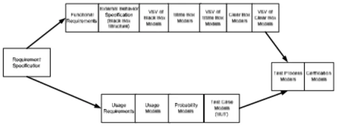
lean Room Software Engineering (CRSE) methodology is basically aimed at developing high quality systems through implementation of formalism and continuous verification and validation models implemented at every stage of the development. Formal methods which are mathematical oriented have been suggested to represent all the phases existing in the development flow of the methodology. CRSE methodology involves two parallel flows, while in one flow the design is undertaken and the other flow deals with undertaking the testing of the code developed through Design Flow. Fig 1.1 shows the CRSE methodology.Embedded systems (ES) must be high quality and fault tolerant systems and are built around the internal and external behavior modeling as they are basically stimulus-response models. Many features of CRSE match with the development requirements of the embedded systems.
However, some changes are needed in the CRSE methodology so that the methodology can be conveniently applied for the development of the embedded systems.
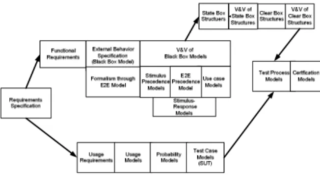
Sastry, Chandra Praksh et al. [1] [2] [3] [4] have recommended the improvement of CRSE model for formalizing the development of the External behavior of the embedded system. The refined CRSE model recommended by them is shown in the Fig. 1.2
The authors further moved on to inventing the formal models, algorithms and the processes for formalizing the development of the internal behavioral models through state box structures.
.
Fig 1.2 Refined CRSE for formalizing the External behavior of the embedded system
2.0 Related work
Harlan D. Mills [5] has recommended constructing the state boxes with the help of Data abstractions that occur in-between the previous stimuli to respond to the effects of the current stimulus. Every data abstraction is regarded as a state and provides for responses when current stimulus happens.
Michel Deck et al. [6] have stated that the state box is the first step of implementing the data specification of black box. In the state box, different aspects of implementation of concrete data structures are considered which include state data and process specification that operates on the data. The abstract models, thus, are restated in terms of the state data. The state data objects are instances of black box data specifications. The state model exists in real programming sense and the state data have initial values. Michel Deck et al. have recommended that the state boxes be derived directly from the black boxes by way of implementing abstract data models. Thus, a hierarchy of the black box to a state box is derived and this hierarchy is generally called as Usage hierarchy since the relationship between BB and SB is determined by usage of one specification by another. The hierarchy also defines a dependency relationship. When a change is made at implementation level, a review at the higher level (BB) must also be undertaken.
Louis Gomes et al. [7] have proposed a method for
deriving the State Charts from use cases. They have considered computational requirements of reactive embedded systems as the basis of representing the functional requirements as a set of state boxes. The model of computation of a reactive system must support concurrency and sequential processing and the
computational model also must support the communication through different interfaces between the concurrent components that form the system. The computational system must also support the representation of the system as hierarchical state box models.
The state chart diagrams, thus, are hierarchically decomposed. The issue of implementation of the state charts lies in the decision of choosing a state chart diagram or the state space of the diagram. The state diagram may be used to implement tasks meant for specifications, simulation and verification where as the state space may be used to implement other non- properties based tasks.
The implementation of the tasks involved in embedded system development can be undertaken based on the state space either directly or indirectly. While the direct implementation is based on the state chart components, indirect implementation is based on previous translation of the start chart into state space. Two of the tools
“Statemate” and “Rhapsody” recommended by David
Harel et al. [8] can be used to directly implement the state charts which are based on the translation of state chart components. The direct implementation of state chart components can be carried using the switch statements, classes (state Chart), Class hierarchy (state chart Hierarchy), Table (Runtime object structure) as defined in the UML.
They have proposed a strategy to implement the state charts using both the direct and indirect implementation. They have proposed a balanced approach which includes direct implementation and handling the issues related to communication, hierarchical refinements, concurrency, and parallelism at higher level of the state charts. Several translation procedures are suggested that lift the issues related to concurrency and communication to the higher levels of the state chart hierarchy. Moreover, the components will be identified such that the implementation of the state charts can be achieved in terms of hardware, software or both.
In all the methods suggested above, not much formalism has been considered and as such the integration of the methods proposed by them into CRSE methodology has not been advocated.
3.0 Pilot Project – “Temperature Monitoring and Controlling of Nuclear Reactor System” (TMCNRS)
A Nuclear reactor is connected with sensing devices such as Temperature sensors, and actuating devices such as heaters and pumps. Both the sensing and actuating devices are connected to the embedded system (TARGET) and the embedded system is connected to a remote computer (HOST) through which the operator monitors and controls the operation of the nuclear reactor.
Fig 3.1 TMCNRS Hardware Integration diagram The temperature sensors are connected to signal conditioners and the outputs of signal conditioners are connected to A/D converter which communicates with Micro Controller using I2C Communication protocol. The output devices which include LCD, interfaces to HOST, and Relay to actuate pumps are connected to the Micro Controller through its output ports.
The access to the embedded system is controlled through a password entered through the key board which is connected to A/D converter. The application running in the embedded system captures the key board strokes and validates the password. The rest of the application is invoked when the password is valid.
Different types of outputs are written on LCD such as Help messages, Sensed temperatures, reference temperatures, and temperature mismatches etc. The HOST is connected to the Microcontroller using RS232C interface. The ES application has the interface for reading the reference temperatures and displaying the same on LCD.
A buzzer is connected to Micro controller and the buzzer is triggered when the difference in temperatures read is more than a threshold level. The ES board is provided with regulated power supply to drive the Micro Controller and to the relays for activating the pumps.
The sensors are mounted on the water tube situated in the mechanical setup. Flow control is achieved through activation and deactivation of the relays that control the Start-stop mechanism of the pumps. Heaters are used to raise the temperature of the Tubes. The Mechanical setup for such an arrangement is shown in the Figure 3.2.
The Embedded Application that runs within the Micro Controller has the following tasks:
1. Read Keyboard entries 2. Validate the password
3. Read Reference Temperatures from HOST 4. Write Initialization output to LCD 5. Write Actual outputs to LCD 6. Read the sensed Temperatures 7. Compare the Temperatures 8. Actuate the buzzers
9. Set and reset the relays to control the pumps 10. Communicate with HOST to transmit the sensed
temperatures
Figure 3.2 Mechanical setup of TMCNRS
4.0 Formal Framework for designing the Internal Behavior of the Embedded System
The framework proposed constitutes several steps of developing models and a process flow to implement the models to realize the state box structure.
4.1 Identification of the objects and their relationships
The first step in the proposed framework is to identify various objects that are involved in the entire application, recognize the relationships among the objects and determine the attributes and the responsibilities of each of the objects. Figures 4.1, 4.2, 4.3 and 4.4show the class diagrams depicting the classes and their relationships.
4.2 Development of a Repository of the Objects
While the class diagrams are drawn, the precedence relationships between the classes are identified and a repository is maintained as shown in the Table 4.1
4.3 Generate the flow sequences
The flow sequences that exist in the class diagrams are drawn using the following algorithm.
Identify the starting points of Data flow by identifying the components that have no preceding components and having stimulus input.
{
For each of the starting components, develop a flow Graph Matrix having rows equivalent to the succeeding components provided no row exists for such a component
{
The presence of the component for a column is indicated through a special symbol inserted in the row column cross section
The type of succeeding component is determined (Backward flow or forward flow). If the succeeding component is in forward flow, is already defined and is situated prior to the current position of the component, then the component in the forward flow is relocated to be the next component in position.
If the succeeding component is in backward flow and is already defined and is situated prior to the current position of the component, then a replication of the component in the backward flow is created to be the next component in position Generally, the replication of the components occurs when the same component serves both inputting and outputting process.
When the flow count of the succeeding component is more than 1, more number of columns are created by way of copying of the current flow and then tracing the flow further from there.
}
All the components are numbered in the order of the flow by using a 4 digit code where the first two digits indicate the position of the component and the next two digits indicate the component code. Appearance of component code at a position which has been already referred in the previous position indicates the reverse flow.
}
Each of the columns in the Flow Graph Matrix indicates a sequence flow with the object structure responsible for realizing a use case. A sample Flow Graph Matrix is shown in the Table 4.2
Fig 4.5 Sequence Flow for the Event “Push Reset button”
4.4 Draw the Sequence Flow Diagrams
The sequence flow diagrams are drawn using the Flow Graph Matrix. Some of the Sequences drawn are shown in the Figures 4.5, 4.6, 4.7, 4.8, 4.9 and 4.10
4.6 Processing flow for capturing keys related to entered password
Operator : <Actor
Name> Micro Controller : <Actor Name>
Initialisation Process : <Process Name>
Process LCD : <Process Name>
LCD : <Actor Name> Reset
Reset
Call
Initialisation Message
Key Board : <Actor
Name> ATODConverter : <Actor Name> Micro Controller : <Actor Name> Intilisation
Process
ProcessKey ProcessLCD LCD
Key Signal
Key Data
Read Key()
process Key
Write Key
Display Key
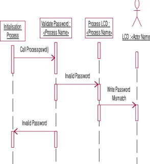
4.7 Processing flow for validating the password
Figure 4.8 Sequence flow for processing the request for inputting the reference Temperatures
Figure 4.9 Sequence Flow for reading Reference Temperature -1
4.5 Generate State Diagrams from Sequence Diagrams
The sequence diagrams which describe various flows that take place across the hardware and software objects of the embedded systems due to occurrence of external and internal stimuli have been derived based on the flows that are traced from the class diagrams. The sequence diagrams provide a basis of recognizing the states of the TMCNRS.
Fig 4.10 Sequence flow for reading Reference Temperature-2
Initialisation Process
Validate Password : <Process Name>
Process LCD : <Process Name>
LCD : <Actor Name>
Call Processpswd()
Invalid Password
Write Password Mismatch
Invalid Password
Initialisation Process
Process LCD : <Process Name>
LCD : <Actor Name>
Request Message reference temparatuers Requestng for inputting
Refrence Temps
Initialisation Process : <Process Name>
Process HOST : <Process Name>
HOST : <Actor Name>
ProcessLCD LCD
REF-1 Request Message
REF-1 Request Message
REF-1 Data
Comm read/write Status
Initialisation Process : <Process Name>
Process HOST : <Process
Name> HOST : <Actor Name>
ProcessLCD LCD
Temp1Sensor : <Actor Name>
Temp2 Sensor : <Actor Name>
REF-2 Request Message
REF-2 Request Message
REF-2 Data
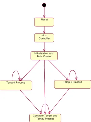
Figure 4.11 Top Level state diagrams
The following Algorithm is used for Generation of State Diagram for modeling Internal Behavior from a set of Sequence Diagram
1. All the major events that drive the TMCNRS are identified with the help of Table 4.1 and Table 4.2
2. For each of the major event, develop a Top Level State. Connect the top level states with transitions using the actors that appear in the last sequence of each of the event. This forms the Top Level State diagram as shown in the figure 4.11
3. For each of the Top Level State, determine the set of sequence flows and their order from the Table 4.2
a. For Each of the Sequence depicted in the Table 4.2 in the proper order
{
a. Select a current sequence flow b. For each of the Input hardware device
in the current sequence, enter a hardware state and develop a state transitions sequentially
c. For each of the Output hardware device, define two states that include
a process state followed by a hardware state as the software drives the hardware and connect the state transitions sequentially
d. For the remaining flow, create a new state for each of the object in the sequence flow and generally name the state with the name of the class to which the object belongs
i. For the First state created, join the Hardware Transition flow ii. Join the Second State to the
First state and so on till all the states are exhausted
iii. Join to the newly created last state with transitions as many times to the Hardware process flow state, based on the number of sequence flows depicted in the sequence Diagram.
iv. For every transition from the newly created states, enter an entry procedure qualified with the name of class and the method name derived from the class in the order in which they are defined in the class. A call to Hardware process method qualified with the name of the class is made. The order in which the entry procedures are included in the state must be same as the order of the methods defined in the class
e. If the current sequence flow has a previous sequence flow, then a transition between the previously created state and currently created state will be maintained.
}
The top level state diagrams generated using the above mentioned algorithm is shown in the Figure 4.11. Each state in the top level State diagram is exploded into further state diagrams based in the composition of elementary level of the states undertaken. The exploded state diagram for the top level state “Initialization” is shown in the Figure 4.12.
The State repositories maps the sequence flows. Two state repositories representing the sequence flows at Fig 4.5
and Fig 4.6 are shown in the Tables 4.3 and 4.4. When a
system enters into a state, some procedures are executed. The procedure execution links the states when the transitions take place. The repository clearly helps in generating the code.
Initialisation and Main Control
Temp-1 Process Temp-2 Process
Compare Temp1 and Temp2 Process
Reset
Name of the Object
Type of the Object
Name of the State
Entry Procedures
Operator Human Operator - Micro
Controller
HW Micro cont
- Initializati
on Process
SW InitMess ages
InitialisationProces s. initMessages() {
ProcessLCD. Command_Write() ProcessLCD. Data_write () }
InitialisationProces s.
displaypasswdMes saage()
{
ProcessLCD. Command_Write() ProcessLCD. Data_write () }
Process LCD
SW LCD Process
ProcessLCD. Command_Write() ProcessLCD. Data_write ()
LCD HW LCD -
Table 4.3 State Repository for the Sequence: Display Init Messages based on the reset button
Name of the Object
Type of the Obje ct
Name of the State
Entry Procedures
Key Board HW Keybaord - ATODConvert
er
HW ATODConv erter Micro
Controller
HW Micro Controller
-InitilisationPro
cess
SW ProcessKey ProcessKey. Readkey () Process LCD SW LCD Process ProcessLCD
.
command_ write () ProcessLCD . data_write ()
LCD HW LCD
-Table 4.4 State Repository for Sequence: Read password through Key strokes
4.6 Develop the Hierarchical State Box structures
The Hierarchy existing in the state charts and sub state charts can be used to present the same as hierarchical state box structures.
5.0 The modified Clean Room Software Engineering Methodology for formalizing internal behavior of embedded systems
Based on the framework proposed in section 4.0 the CRSE methodology has been further refined and the same is placed in the Figure 4.11
Fig 4.11 The Refined CRSE model due to formalism for modeling the internal behavior of the embedded systems
6.0 Conclusions
There is a necessity that formalism be introduced in CRSE methodology and redefine the same so that the refined methodology can be conveniently be applied for the development of embedded systems.
The paper has provided a flow and three models based on UML artifacts for formalizing the internal behavior modeling of the embedded systems.
References
[2] Prof. V. Chandra Prakash, Dr Sastry JKR et al., “A formal framework for presenting requirements specifications of an embedded systems as a Black box structure”, Proceedings of International Joint Conference on Information and Communication Technology (IJCICT-2010) January, 2010
[3] Dr Sastry JKR, Prof. V. Chandra Prakash et al., “A formal Framework for Modeling External Behavior of an embedded system as a Black Box structure”, Proceedings of IEEE sponsored 4th International Conference on "Embedded and Multimedia Computing", EM-Com 2009 Dec 2009.
[4] Dr Sastry JKR, Prof. V. Chandra Prakash et al., “A formal Framework for Verification and Validation of External Behavior models of embedded systems through Use Case Models”, IEEE sponsored 4th International Conference on "Embedded and Multimedia Computing", EM-Com 2009 Dec 2009. [5] Harlan D. Mills, “Stepwise Refinement and
Verification in Box-Structured Systems”, Journal IEEE Computer, Jun-88, Volume 21 Issue 6, Page 23-36
[6] Michael Deck, “Data Abstraction in the Box structures Approach”, 3rd International conference on Cleanroom Software Engineering practices, Oct 10-11, 1996, college park, MD
[7] Louis Gomes and Aniko Costa, “From Use Cases to System Implementation: State chart based Co-design”, Proceedings of the First ACM and IEEE International Conference on Formal Methods and Models for Co-Design (MEMOCODE’03) 2003. [8] D. Harel and E. Gerry, “Executable Object Modeling
with State charts”, Computer, pages 31–42, July 1997.
Authors Biography
Dr JKR Sastry is presently working as Professor of
Computer Science and Engineering at K L University, Vaddeswaram and has 35 years of experience in the field of Information Technology. Has served the IT industry for 29 years worldwide and has been serving the Educational Institutes for the last 6 years. Has published 45 papers in the fields of Embedded Systems, Data warehousing, Data Mining, Software Engineering and Wireless Communication in the International Journals and Conferences. Has been the reviewer for several IEEE sponsored International and National Conferences. Has Chaired 2 International Conferences. Has directed 4 Ph.D. programs and has been directing 8 Ph.D. programs concurrently.
Prof. V. Chandra Prakash is presently working in the department of Computer Science and Engineering at K L University, Vaddeswaram and has 35 years of experience spanning across the Industry and Educational institutes. He has so far published 13 papers in the International Journals and Conferences in the field of Software Engineering and Embedded systems.
Figure 4.1 Class diagram for Initialization Setup
Fig 4.2 Class Diagram for processing Temperature-1
Reset-ST11/RS23
INT-ST7 INT-ST8
ST2-ST6
RestButton Char Component Type = H
HOST
int latency char component type = H
Process-Type = H Send Ref1() Send Ref2() Read MAC Code()
readPIN() (f rom Business Use-C...) ST7
ST8
KeyBoard Char Component Type = H int latency
MicroController Char Component type = H Int Latency
LCD Char Component Type = H int latency
Proces sHOST int latency char component type = S Process-Type=H s end temp1() s end temp2() Read Ref1() Read Ref2() s endrequest() <<process>> RS10 RS11 ValidatePassword
Char Component Type = S proces s LCD()
<<process>> ATODConverter
Int Latency Char Component Type = H
InitializationProcess Char Component Type = P Process LCD1()/Process LCD() Process Key/Proces s Key() Process Message()
Validate PAs sword/Validate Password() Process HOST/Communication with HOST() schedule tasks ()
startos () create stacks ()
<<process>> Invalid password
Process Lcd int latency char component type = S Process-Type=H : Byte bus y check LCD() Initialise LCD() write LCD()
<<process>> RS1, RS2, RS3-RS7, RS8, RS9
ProcessKey char Com ponent Type = S Process -Type=H low Count = 5 Read Key1() Read Key2() Read Key3() Read Key4() Read Key5() <<process>> Tsensor1 Pump1 Char Component Type = H int latency
TemperatureSensor1 Char Componet Type = H Int Lattency
ST9
LCD Char Component Type = H int latency
HOST
int latency char component type = H
Process-Type = H
(f rom Business Use-C...)
Relay1 Char Component Type = H int latency
OpertionalAmplifier1 Char Component Type = H Int latency
ProcessLcd int latency char component type = S Process-Type=H : Byte busy check LCD() Initialise LCD() write LCD() <<process>> RS22 ProcessHOST int latency char component type = S Process-Type=H send temp1() send temp2() Read Ref1() Read Ref2() sendrequest() <<process>> RS14 MicroController Char Component type = H Int Latency
CompareTemp1Task int latency char component Type = S assert relay1/Relay1() deassert relay1/Relay2() <<process>> RS18 RS19 ATODConverter Int Latency Char Component Type = ...
Temp1Task char Component Type = S Int Priority = 100 Int latency read Temp1() ...
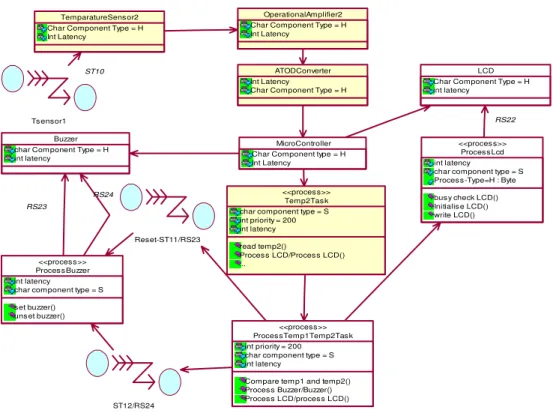
Fig 4.3 Class Diagram for processing Temperature-2
Fig 4.4 Class Diagram for processing Temperature Thresholds ST12/RS24
Pump2 int latency char Component Type = H TemparatureSensor2
Char Component Type = H Int Latency ST10
LCD Char Component Type = H int latency
HOST
Send Ref1() Send Ref2() Read MAC Code()
readPIN()
(f rom Business Use-C...)
Relay2 Char com ponent type = H int latency OperationalAmplifier2
Char Component Type = H Int Latency
Process HOST int latency char component type = S Process -Type=H send tem p1() send tem p2() Read Ref1() Read Ref2() sendrequest() <<process>> RS15 ProcessLcd int latency char component type = S Proces s-Type=H : Byte busy check LCD() Initialis e LCD() write LCD()
<<process>> RS22 MicroController
Char Component type = H Int Latency
CompareTemp2Task int latency char componet type = s as sert relay2/Relay2() de assert relay2/Relay2()
<<process>>
RS21 RS20 ATODConverter
Int Latency Char Component Type = H
Temp2Task char component type = S int priority = 200 int latency read temp2() Process LCD/Process LCD() Compare with Ref 2() ...
<<process>>
Tsensor1
TemparatureSensor2 Char Component Type = H Int Latency
ST10
OperationalAmplifier2 Char Component Type = H Int Latency
ProcessLcd int latency
char component type = S Process-Type=H : Byte busy check LCD() Initialise LCD() write LCD()
<<process>> LCD Char Component Type = H int latency
RS22
ATODConverter Int Latency
Char Component Type = H
Temp2Task char component type = S int priority = 200 int latency read temp2()
Process LCD/Process LCD() ...
<<process>>
ProcessTemp1Temp2Task int priority = 200
char component type = S int latency
Compare temp1 and temp2() Process Buzzer/Buzzer() Process LCD/process LCD()
<<process>> MicroController Char Component type = H Int Latency
ST12/RS24 Reset-ST11/RS23 Buzzer
char Component Type = H int latency
ProcessBuzzer int latency
char component type = S set buzzer() unset buzzer()
<<process>>
RS23
Figure 4.12 Sub-Level State diagrams for the Top Level State Initialization and Main Control
Serial Number of Component
Name of the Process Component
Type of Process Component (H- hardware, S-Software)
Preceding components
1 ResetButton H
2 MicroController H ResetButton
ATOD Converter HOST
3 HOST H ProcessHOST
4 LCD H ProcessLCD
MicroController
5 ATODConverter H Process Key
Temp1Task Temp2Task KeyBoard
OperationalAmplifier1 OperationalAmplifier2
6 KeyBoard H
7 Temp1Sensor H
8 Temp2Sensor H
9 OperationalAmplifier 1
H Temp1Sensor 10 OperationalAmplifier
2
H Temp2Sensor
11 Buzzer H ProcessBuzzer
MicroController
12 Pump1 H Relay1
Init Mes s ages
Proces s Key
Validate Pas s word
Read Reference1
Proces s Hos t
LCD Proces s
LCD
HOST
Invalid Pas swd Mes g
M1 M2
key value KeyBaord
Res et Micro
Controlle ATODConverter
Init reference
Read Reference 2 Reference1 data
13 Pump2 H Relay2
14 Relay1 H CompareTemp1Task
MicroController
15 Relay2 H CompareTemp2Task
MicroController
16 ProcessKey S InitializationProcess
17 ValidatePassword S InitializationProcess
18 ProcessLCD S InitializationProcess
ValidatePassword Temp1Task Temp2Task ProcessHOST
ProcessTemp1Temp2Task 19 InitializationProcess S MicroController
20 ProcessHOST S Initialization Process
Temp1Task Temp2Task HOST
21 Temp1Task S MicroController
ATODConverter
22 Temp2Task S Micro Controller
ATODConverter
23 CompareTemp1Task S Temp1Task
24 CompareTemp2Task S Temp2Task
25 ProcessTemp1Temp2 Task
S MicroController
MicroController
26 Process Buzzer S ProcessTemp1Temp2Task
Serial Number of Component
Name of the Component Type of component
(H- hardware, S-Software)
Reset Event
Push Reset Button ST1
Press Key1 to Key5
Validate Password
Request for Inputting Ref Temps
Read Ref Temp-1
Read Ref Temp-2
0101 ResetButton H √
0102 Wait1
0202 KeyBoard H √
0303 Temp1Sensor H
0404 Temp2Sensor H
0505 OperationalAmplifier1 H
0606 OperationalAmplifier2 H
0707 ATODConverter H √
0808 HOST H √ √
0909 ProcessHOST S √ √
1010 MicroController H √ √
1111 InitializationProcess S √ √ √ √ √ √
1212 ValidateProcess S √
1313 ProcessKey S √
1414 Temp1Task S
1515 Temp2Task S
1616 CompareTemp1Task S
1717 CompareTemp2Task S
1818 ProcessTemp1Temp2Task S
1919 ProcessLCD S √ √ √ √ √ √
2020 LCD H √ √ √ √ √ √
2112 ValidationProcess S √
2211 InitializationProcess S √
2309 ProcessHOST S
2408 HOST H
2525 ProcessBuzzer S
2626 Buzzer H
2727 Relay1 H
2828 Pump1 H
2929 Relay2 H
3030 Pump2 H