Table Of Contents
Overview ...1
PCB, PCM and PCH Overview ...1
Technical Support...1
Installation ...2
Invoking the Command Line Compiler ...2
MPLAB Integration ...4
Directories ...4
File Formats...5
Direct Device Programming ...5
Device Calibration Data...5
Utility Programs ...6
PCW IDE ...7
File Menu ...7
Project Menu ...8
Edit Menu ...9
Options Menu ...10
Compile...13
View Menu ...13
Tools Menu...16
Help Menu ...18
PCW Editor Keys...19
Project Wizard ...21
CCS Debugger...23
Debugger - Overview...23
Debugger - Menu...23
Debugger - Configure ...23
Debugger - Control ...24
Debugger- Enable/Disable ...24
Debugger - Watches...24
Debugger - Breaks ...25
Debugger - RAM...25
Debugger - ROM ...25
Debugger -Data EEPROM ...25
Debugger - Stack...26
Debugger - Eval...26
Debugger - Log...26
Debugger - Monitor...26
Debugger - Peripherals ...27
Debugger - Snapshot ...27
PRE-PROCESSOR ...29 Pre-Processor Directives...30 #ASM ...30 #ENDASM ...30 #BIT ...34 #BUILD ...34 #BYTE ...35 #CASE ...36 __DATE__ ...37 #DEFINE ...37 #DEVICE ...38 __DEVICE__ ...39 #ERROR...39 __FILE__ ...40 #FILL_ROM ...40 #FUSES...41 #ID ...42 #IF expr...43 #ELSE...43 #ELIF ...43 #ENDIF ...43 #IGNORE_WARNINGS...44 #IFDEF ...44 #IFNDEF...44 #ELSE...44 #ELIF ...44 #ENDIF ...44 #INCLUDE...45 #INLINE ...46 #INT_xxxx...46 #INT_DEFAULT ...48 #INT_GLOBAL ...49 __LINE__...49 #LIST ...50 #LOCATE ...50 #NOLIST...51 #OPT ...51 #ORG...52 __PCB__ ...53 __PCM__...54
__PCH __ ...54
#PRAGMA ...55
#RESERVE ...56
#ROM ...56
#SERIALIZE ...57
#SEPARATE ...59
__TIME __ ...59
#TYPE ...60
#UNDEF ...60
#USE DELAY ...61
#USE FAST_IO ...61
#USE FIXED_IO...62
#USE I2C...63
#USE RS232 ...64
#USE STANDARD_IO...67
#ZERO_RAM...67
Data Definitions...69
Data Types ...69
Function Definition ...71
Function Definition...71
Reference Parameters ...72
C Statements And Expressions ...73
Program Syntax...73
Comment ...73
STATEMENTS ...74
Expressions ...75
Operators...76
Operator Precedence ...77
Trigraph Sequences ...77
Built-In Functions ...79
ISPUNCT(x)...112 ISAMOUNG()...113 KBHIT()...114 LABEL_ADDRESS()...115 LABS() ...116 LCD_LOAD() ...116 LCD_SYMBOL() ...117 LDEXP() ...118 LOG()...119 LOG10()...120 MAKE8() ...121 MAKE16() ...121 MAKE32() ...122 MALLOC() ...123 MEMCPY() ...123 MEMMOVE() ...123 MEMSET() ...124 MODF()...125 OFFSETOF() ...126 OFFSETOFBIT() ...126 OUTPUT_A() ...127 OUTPUT_B() ...127 OUTPUT_C()...127 OUTPUT_D()...127 OUTPUT_E() ...127 OUTPUT_BIT()...127 OUTPUT_FLOAT()...128 OUTPUT_HIGH() ...129 OUTPUT_LOW() ...130 OUTPUT_TOGGLE() ...130 PERROR() ...131 PORT_A_PULLUPS() ...132 PORT_B_PULLUPS() ...132 POW()...133
POWER CONTROL PWM...134
SETUP_COMPARATOR() ...159 SETUP_COUNTERS() ...160 SETUP_EXTERNAL_MEMORY()...161 SETUP_LCD() ...162 SETUP_OSCILLATOR() ...162 SETUP_POWER_PWM()...164 SETUP_POWER_PWM_PINS() ...165 SETUP_PSP() ...166 SETUP_SPI() ...167 SETUP_TIMER_0() ...167 SETUP_TIMER_1() ...168 SETUP_TIMER_2() ...169 SETUP_TIMER_3() ...170 SETUP_TIMER_5() ...172 SETUP_UART() ...172 SETUP_VREF()...173 SETUP_WDT() ...174 SHIFT_LEFT() ...175 SHIFT_RIGHT()...176 SIN() ...177 COS()...177 TAN() ...177 ASIN() ...177 ACOS() ...177 ATAN()...177 SINH()...177 COSH() ...177 TANH()...177 ATAN2()...177 SINH()...179 SLEEP()...179 SPI_DATA_IS_IN()...180 SPI_READ() ...180 SPI_WRITE()...181 SPRINTF() ...182 SQRT() ...183 SRAND()...184
STANDARD STRING FUNCTIONS ...184
MEMCHR() ...184
MEMCMP() ...184
STRCAT() ...184
STRCHR() ...184
STRCOLL()...184 STRCSPN() ...184 STRICMP() ...184 STRLEN() ...184 STRLWR() ...185 STRNCAT() ...185 STRNCMP() ...185 STRNCPY() ...185 STRPBRK() ...185 STRRCHR()...185 STRSPN()...185 STRSTR() ...185 STRXFRM() ...185 STRCPY()...187 STRTOD() ...187 STRTOK()...188 STRTOL() ...189 STRTOUL() ...190 SWAP()...191 TAN() ...192 TANH()...192 TOLOWER() ...192 TOUPPER()...192 WRITE_BANK()...193 WRITE_EEPROM() ...194 WRITE_EXTERNAL_MEMORY() ...196 WRITE_PROGRAM_EEPROM() ...197 WRITE_PROGRAM_MEMORY()...197
Standard C Definitions ...199
errno.h ...199 float.h ...199 limits.h...201 locale.h ...201 setjmp.h ...201 stddef.h ...202 stdio.h ...202 stdlib.h ...203
Compiler Error Messages ...205
Compiler Warning Messages ...216
Common Questions And Answers ...219
How does one map a variable to an I/O port?...219
Why is the RS-232 not working right? ...221
How does the PIC® connect to a PC? ...224
What can be done about an OUT OF RAM error?...225
Why does the .LST file look out of order? ...226
How does the compiler determine TRUE and FALSE on expressions? ...227
Why does the compiler use the obsolete TRIS? ...228
How does the PIC® connect to an I2C device? ...229
Instead of 800, the compiler calls 0. Why?...229
Instead of A0, the compiler is using register 20. Why? ...230
How do I directly read/write to internal registers? ...231
How can a constant data table be placed in ROM? ...232
How can the RB interrupt be used to detect a button press?...233
What is the format of floating point numbers?...234
Why does the compiler show less RAM than there really is? ...235
What is an easy way for two or more PICs® to communicate? ...236
How do I write variables to EEPROM that are not a byte? ...237
How do I get getc() to timeout after a specified time?...238
How can I pass a variable to functions like OUTPUT_HIGH()? ...239
How do I put a NOP at location 0 for the ICD? ...240
How do I do a printf to a string? ...240
How do I make a pointer to a function?...241
How much time do math operations take? ...242
How are type conversions handled? ...243
Example Programs...245
EXAMPLE PROGRAMS...245
Overview
PCB, PCM and PCH Overview
The PCB, PCM and PCH are separate compilers. PCB is for 12 bit opcodes, PCM is for 14 bit opcodes and PCH is for the 16 and 18 bit PICmicro® MCU. Since much is in common among the compilers, all three are covered in this reference manual. Features and limitations that apply to only specific controllers are indicated within. These compilers are specially designed to meet the unique needs of the PICmicro® MCU controllers. These tools allow developers to quickly design application software for these controllers in a highly readable, high-level language.
The compilers have some limitations when compared to a more traditional C compiler. The hardware limitations make many traditional C compilers ineffective. As an example of the limitations, the compilers will not permit pointers to constant arrays. This is due to the separate code/data segments in the PICmicro® MCU hardware and the inability to treat ROM areas as data. On the other hand, the compilers have knowledge about the hardware limitations and do the work of deciding how to best implement your algorithms. The compilers can efficiently implement normal C constructs, input/output operations and bit twiddling operations.
Technical Support
The latest software can be downloaded via the Internet at:
http://www.ccsinfo.com/download.shtml
for 30 days after the initial purchase. For one year’s worth of updates, you can purchase a Maintenance Plan directly from CCS. Also found on our web page are known bugs, the latest version of the software, and other news about the compiler.
Secondly, if we are unable to solve your problem by email, feel free to telephone us at (262) 797-0455 x 32. Please have all your supporting documentation on-hand so that your questions can be answered in an efficient manner. Again, we will make every attempt to solve any problem(s) that you may have. Suggestions for improving our software are always welcome and appreciated.
Installation
PCB, PCM, and PCH Installation:
Insert the disk in drive A and from Windows Start|Run type: A:SETUP
PCW Installation:
Insert CD ROM, select each of the programs you wish to install and follow the on-screen instructions.
Invoking the Command Line Compiler
The command line compiler is invoked with the following command:
CCSC options cfilename
Valid options:
+FB Select PCB (12 bit) -D Do not create debug file
+FM Select PCM (14 bit) +DS Standard .COD format debug file +FH Select PCH
(PIC18XXX)
+DM .MAP format debug file
+FS Select SXC (SX) +DC Expanded .COD format debug file
+ES Standard error file +EO Old error file format +T Create call tree (.TRE) -T Do not generate a tree file +A Create stats file (.STA) -A Do not generate a statistics file +EW Show warning
messages
-EW Suppress warnings (use with +EA)
+EA Show all error messages and all warnings
-E Only show first error
+Yx Optimization level x (0-9) +DF Enables the ouput of a COFF debug file.
+LNxxx Normal list file +O8xxx 8 bit Intel HEX output file +LSxxx MPASM format +OWxxx 16 bit Intel HEX output file +LOxxx Old MPASM list file +OBxxx Binary output file
+LYxxx Symbolic list file -O Do not create object file -L Do not create list file
+P Keep compile status window up after compile +Pxx Keep status window up for xx seconds after compile +PN Keep status window up only if there are no errors +PE Keep status window up only if there are errors
+Z Keep scratch files on disk after compile -Z Do not keep compiler scratch files
+DF COFF Debug file
I+="..." Same as I="..." Except the path list is appended to the current list
I="..." Set include directory search path, for example:
I="c:\picc\examples;c:\picc\myincludes"
If no I= appears on the command line the .PJT file will be used to supply the include file paths.
-P Close compile window after compile is complete +M Generate a symbol file (.SYM)
-M Do not create symbol file +J Create a project file (.PJT) -J Do not create PJT file +ICD Compile for use with an ICD +? Brings up a help file
-? Same as +?
#xxx="yyy" Set a global #define for id xxx with a value of yyy, example:
#debug="true"
+Gxxx="yyy" Same as #xxx="yyy"
+STDOUT Outputs errors to STDOUT (for use with third party editors) +SETUP Install CCSC into MPLAB (no compile is done)
+V Show compiler version (no compile is done)
+Q Show all valid devices in database (no compile is done)
A / character may be used in place of a + character. The default options are as follows:
If @filename appears on the CCSC command line, command line options will be read from the specified file. Parameters may appear on multiple lines in the file.
If the file CCSC.INI exists in the same directory as CCSC.EXE, then command line parameters are read from that file before they are processed on the command line.
Examples:
CCSC +FM C:\PICSTUFF\TEST.C CCSC +FM +P +T TEST.C
MPLAB Integration
MPLAB 5:
If MPLAB is installed before the compiler, then integration with MPLAB is automatic. Otherwise use the following command:
CCSC +SETUP
MPLAB 6:
A plug-in program must be executed on the computer with MPLAB 6 before MPLAB 6 can use the CCS C compiler. If this plug-in did not come with your version of MPLAB you should download it from the download page of the CCS web site.
The specific instructions for compiling and running from MPLAB will vary depending on the version. In general when creating a project be sure to select the CCS C Compiler as the tool suite, then follow the normal MPLAB instructions.
To download the latest version of MPLAB to go Microchip's web page at: http://www.microchip.com
Directories
The compiler will search the following directories for Include files.
• Directories listed on the command line
• Directories specified in the .PJT file
• The same directory as the source file
The compiler itself is a DLL file. The DLL files are in a DLL directory by default in C:\Program Files\PICC\DLL. Old compiler versions may be kept by renaming this directory.
File Formats
The compiler can output 8 bit hex, 16 bit hex, and binary files. Two listing formats are available. Standard format resembles the Microchip tools and may be required by some third-party tools. The simple format is easier to read. The debug file may either be a Microchip .COD file or Advanced Transdata .MAP file. All file formats and extensions are selected via the Options|File Formats menu option in the Windows IDE.
Direct Device Programming
The IDE has a program option in the main menu bar. When invoked, the IDE will issue a command to start the user's device programmer. The commands are specified in the Options|Debugger/Programer window. The %H is replaced with the HEX filename and %D is replaced with the device number. Put a ! at the end of the command line if you would like a pause before returning to IDE. Only programs that can be invoked by a command will work with this option.
Device Calibration Data
Some devices from Microchip have calibration data programmed into the program area when shipped from the factory. Each part has its own unique data. This poses some special problems during development. When an UV erasable (windowed) part is erased, the calibration data is erased as well. Calibration data can be forced into the chip during programming by using a #ROM directive with the appropriate data.
Utility Programs
SIOW SIOW is a Windows utility (PCW only). SIOW is a simple "dumb terminal" program that may be run on a PC to perform input and output over a serial port. SIOW is handy since it will show all incoming characters. If the character is not a normally displayable character, it will show the hex code.
DEVEDIT DEVEDIT is a Windows utility (PCW only) that will edit the device database. The compiler uses the device database to determine specific device characteristics at compile time. This utility will allow devices to be added, modified or removed. To add a device, highlight the closest equivalent chip and click on COPY. To edit or delete, highlight the device and click on the appropriate button.
PCONVERT PCONVERT is a Windows utility (PCW only) that will perform conversions from various data types to other types. For example, Floating Point decimal to 4 BYTE Hex. The utility opens a small window to perform the conversions. This window can remain active during a PCW or MPLAB session. This can be useful during debugging.
CCSC +Q This will list all devices in the compiler database.
PCW IDE
File Menu
New Creates a new file
Open Opens a file into the editor. If there are no other files open then the project name is set to this files name. Ctrl-O is the shortcut.
Reopen Lists all the recently used files and allows the user to open them by selecting the appropriate file.
Save Saves the file currently selected for editing. Ctrl-S is the shortcut.
Save As Prompts for a filename to save the currently selected file.
Close Closes the file currently open for editing. Note that while a file is open in PCW for editing no other program may access the file. Shift F11 is the shortcut.
Close All Closes all files.
Print Prints the currently selected file.
Printer Setup Allows the selection of a printer and the printer settings.
Exit Terminates PCW
Project Menu
New Creates a new project. A project may be created manually or via a wizard. If created manually only a .PJT file is created to hold basic project information. An existing .C main file may be specified or an empty one may be created. The wizard will allow the user to specify project parameters and when complete a .C, .H and .PJT file are created. Standard source code and constants are generated based on the specified project parameters.
New| PICWIZARD
This command will bring up a number of fill-in-the-blank forms about your new project. RS232 I/O and i2C characteristics, timer options, interrupts used, A/D options, drivers needed and pin names all may be specified in the forms. When drivers are selected, the tool selects pins required and pins that can be combined will be. The user may edit the final pins selections. After all selections are made the initial .c and .h files are created with #defines, #includes and initialization commands required for your project. This is a fast way to start a new project. Once the files are created you cannot return to the menus to make further changes.
Open All Files
A .PJT file is specified and all files used in the project are opened. In order for this function to work the program must have been compiled in order for the include files to become known.
Reopen Lists all the recently used project files and allows the user to open them by selecting the appropriate file.
Find Text In Project
Searches all files in a project for a given text string.
Print All Files All files in the project are printed. For this function to work the program must have been compiled in order for the include files to become known.
Include Dirs Allows the specification of each directory to be used to search for include files for just this project. This information is saved in the .PJT file.
Close Project Closes all files associated with the current project.
Edit Menu
Undo Undoes the last deletion.
Cut Moves the selected text from the file to the clipboard.
Copy Copies the selected text to the clipboard.
Paste Copies the clipboard contents to the cursor location.
Select All Highlight all text within the file.
Copy from File
Copies the contents of a file to the cursor location.
Paste to File
Pastes the selected text to a file.
Find Searches for a specified string in the file.
Replace Replaces a specified string with a new string.
Match Brace Highlights the matching { or ). The editor will start counting the open and closed braces and highlight the closing or opening item when they match. Simply place the cursor on one of the items and the matching one will be highlighted.
Match Brace Extended
The text will be highlighted up to the corresponding } or ).
Indent Selection
Indents the highlighted text
Toggle Bookmark
Sets a bookmark (0-9) at the cursor location.
Goto Bookmark
Move the cursor to the specified bookmark (0-9).
Next Window Selects the next open file as the current file for editing.
Previous Window
Selects the previous open file as the current file for editing.
Indent Selection
The selected area of code will be properly indented.
Options Menu
Recall Open Files
When selected PCW will always start with the same files open as were open when it last shut down. When not selected PCW always starts with no files open.
Editor Properties
When clicked the editor brings up a new Editor Properties Window which gives the user a number of options for setting up the editor properties. Editor Properties window have three tabs which are explained below:
General Tab:
Window Settings:
Editor Options:
Syntax Highlighting
When checked the editor highlights in color C keywords and comments.
Auto Highlight brackets
When checked the editor highlights the matching brackets automatically when the cursor is placed on one.
Auto Indent
When selected and the ENTER is pressed the cursor moves to the next line under the first character in the previous line. When not selected the ENTER always moves to the beginning of the next line.
WordStar keys
When selected the editing keys are WordStar style. WordStar commands will enable additional keystrokes recognized by the editors. See EDITOR for more information.
TABS:
Tab size
Determines the number of characters between tab positions. Tabs allow you to set the number of spaces equated by a tab and whether or not the tabs are converted to spaces or left as tabs.
Keep Tabs
When selected the editor inserts a tab character (ASCII 9) when the TAB key is pressed.
Insert Spaces
When selected and the TAB key is pressed, spaces are inserted up to the next tab position.
Display Tab:
Margin
Visible left Margin
When selected the left margin of the editor becomes visible.
Visible Right Margin
Left Margin Width Width of the left margin.
Right Margin
Position of the right margin.
Editor Font
Selects the font of the editor.
Font Size:
Size of the editor font.
Font Style
Style of the editor font (Italic/Bold/Underline).
Color Tab: This tab allows the user to select the color for syntax highlighting.
Customize This option gives a list of icons that can be added to the tool bar for speedy access of functionalities of the debugger.
File Formats
Allows selection of the output file formats.
Debug File Options
Microchip COD Standard PICmicro® MCU debug file
RICE16 MAP Used only be older RICE16 S/W To Extended COD COD file with advanced debug info
List Format Options
Simple A basic format with C code and ASM
Standard The MPASM standard format with machine code
Old Older MPASM format
Object file extension The file extension for a HEX file
List file extension The file extension for a list file
Object File Options
8 bit HEX 8 Bit Intel HEX file 16 bit HEX 16 bit Intel HEX file
Binary Straight binary (No fuse info)
Error File Options
Standard Current Microchip standard Original Older Microchip standard
Include Dirs
Allows the specification of each directory to be used to search for include files by default for newly created projects. This has no effect on projects already created (use Project|Include Dirs to change those).
Debugger/ Programmer
Allows the specification of the device programmer to be used when the PROGRAM CHIP tool is selected.
Global Definitions
Allows the setting of #defines to be used in compiling. This is the same as having some #defines at the top of your program. This may be used for example to set debugging defines without changing the code.
Compile
PCW Compile
Compiles the current project (name is in lower right) using the current compiler (name is on the toolbar).
View Menu
C/ASM Opens the listing file in read only mode. The file must have been compiled to view the list file. If open, this file will be updated after each compile. The listing file shows each C source line and the associated assembly code generated for the line.
For Example:
0F4: DESCZ 08,F 0F5: GOTO 0F4
……….while input(pin_0)); 0F6: BSF 0B,3
Symbol Map Opens the symbol file in read only mode. The file must have been compiled to view the symbol file. If open, this file will be updated after each compile. The symbol map shows each register location and what program variables are saved in each location.
Displays the RAM memory map for the program last compiled. The map indicates the usage of each RAM location. Some locations have multiple definitions since RAM is reused depending on the current procedure being executed.
For Example:
08 @SCRATCH
09 @SCRATCH 0A TRIS_A 0B TRIS_B 0C MAIN.SCALE
0D MAIN.TIME
0E GET_SCALE.SCALE 0E PUTHEX.N
0E MAIN.@SCRATCH
Call Tree Opens the tree file in read only mode. The file must have been compiled to view the tree file. If open, this file will be updated after each compile. The call tree shows each function and what functions it calls along with the ROM and RAM usage for each.
For Example: Main 0/30 INIT 0/6
WAIT_FOR_HOST 0/23 (Inline) DELAY_US 0/12
SEND_DATA 0/65
Statistics Opens the stats file in read only mode. The file must have been compiled to view the stats file. If open, this file will be updated after each compile. The statistics file shows each function, the ROM and RAM usage by file, segment and name.
Data Sheet This tool will bring up Acrobat Reader with the manufacture data sheet for the selected part. If data sheets were not copied to disk, then the CCS CD ROM or a manufacture CD ROM must be inserted.
Binary file Opens a binary file in read only mode. The file is shown in HEX and ASCII.
COD Debug file Opens a debug file in read only mode. The file is shown in an interpreted form.
Valid Fuses Shows a list of all valid keywords for the #fuses directive for this device.
Tools Menu
Device Editor This tool allows the essential characteristics for each supported processor to be specified. This tool edits a database used by the compiler to control the compilation. CCS maintains this database (Devices.dat) however users may want to add new devices or change the entries for a device for a special application. Be aware if the database is changed and then the software is updated, the changes will be lost. Save your DEVICES.DAT file during an update to prevent this.
Device Selector This tool uses the device database to allow a parametric selection of devices. By selecting key characteristics the tool displays all eligible devices.
File Compare Compares two files. When source or text file is selected, then a normal line by line compare is done. When list file is selected the compare may be set to ignore RAM and/or ROM addresses to make the comparison more meaningful. For example if an asm line was added at the beginning of the program a normal compare would flag every line as different. By ignoring ROM addresses then only the extra line is flagged as changed. Two output formats are available. One for display and one for files or printing.
Numeric Converter A conversion tool to convert between decimal, hex and float.
Serial Port Monitor
An easy to use tool to connect to a serial port. This tool is convenient to communicate with a target program over an RS232 link. Data is shown as ASCII characters and as raw hex.
Disassembler This tool will take as input a HEX file and will output ASM. The ASM may be in a form that can be used as inline ASM.
assembly file so that selected sections can be extracted and inserted into your C programs as inline assembly. Options will allow the selection of the assembly format.
• 12 or 14 bit opcodes
• Address, C, MC ASM labels
• Hex or Binary
• Simple, ASM, C numbers
Extract Cal Data
This tool will take as input a HEX file and will extract the calibration data to a C include file. This may be used to maintain calibration data for a UV erasable part. By including the include file in a program the calibration data will be restored after re-burning the part.
Program Chip This simply invokes device programmer software with the output file as specified in the Compile\Options window. This command will invoke the device programmer software of your choice. Use the compile options to establish the command line.
MPLAB Invokes MPLAB with the current project. The project is closed so MPLAB may modify the files if needed. When MPLAB is invoked this way PCW stays minimized until MPLAB terminates and then the project is reloaded.
Internet These options invoke your WWW browser with the requested CCS Internet page:
Check for Software Updates
Automatically starts your internet program and routes to CCS web site to check for new software releases.
Download Software Updates
Automatically download new software with a valid reference number.
Maintenance Prices
Compiler News An internet site devoted to the current happenings of the PIC.
PIC Web Resources
View a web site dedicated for hardware and software for the PIC.
Data Sheets for Device Drivers
A list of various manufacture data sheets for devices CCS has device drivers for (such as EEPROMs, A/D converters, RTC...)
Help Menu
About Shows the version of the IDE and each installed compiler.
Contents The help file table of contents.
Index The help file index.
Keyword at cursor Does an index search for the keyword at the cursor location. Press F1 to use this feature.
F12 Bring up help index
PCW Editor Keys
Cursor Movement
Left Arrow Move cursor one character to the left Right Arrow Move cursor one character to the right Up Arrow Move cursor one line up
Down Arrow Move cursor one line down Ctrl Left Arrow Move cursor one word to the left Ctrl Right Arrow Move cursor one word to the right Home Move cursor to start of line End Move cursor to end of line Ctrl PgUp Move cursor to top of window Ctrl PgDn Move cursor to bottom of window PgUp Move cursor to previous page PgDn Move cursor to next page Ctrl Home Move cursor to beginning of file Ctrl End Move cursor to end of file
Ctrl S Move cursor one character to the left Ctrl D Move cursor one character to the right Ctrl E Move cursor one line up
Ctrl X ** Move cursor one line down Ctrl A Move cursor one word to the left Ctrl F Move cursor one word to the right Ctrl Q S Move cursor to top of window Ctrl Q D Move cursor to bottom of window Ctrl R Move cursor to beginning of file Ctrl C * Move cursor to end of file
Shift ~ Where ~ is any of the above: Extend selected area as cursor moves
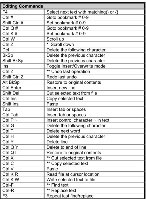
Editing Commands
F4 Select next text with matching() or {} Ctrl # Goto bookmark # 0-9
Shift Ctrl # Set bookmark # 0-9 Ctrl Q # Goto bookmark # 0-9 Ctrl K # Set bookmark # 0-9
Ctrl W Scroll up
Ctrl Z * Scroll down
Del Delete the following character BkSp Delete the previous character Shift BkSp Delete the previous character Ins Toggle Insert/Overwrite mode Ctrl Z ** Undo last operation
Shift Ctrl Z Redo last undo
Alt BkSp Restore to original contents Ctrl Enter Insert new line
Shift Del Cut selected text from file Ctrl Ins Copy selected text Shift Ins Paste
Tab Insert tab or spaces Ctrl Tab Insert tab or spaces
Ctrl P ~ Insert control character ~ in text Ctrl G Delete the following character Ctrl T Delete next word
Ctrl H Delete the previous character Ctrl Y Delete line
Ctrl Q Y Delete to end of line Ctrl Q L Restore to original contents Ctrl X ** Cut selected text from file Ctrl C ** Copy selected text
Ctrl V Paste
Ctrl K R Read file at cursor location Ctrl K W Write selected text to file Ctrl-F ** Find text
Ctrl-R ** Replace text
F3 Repeat last find/replace
Project Wizard
The new project wizard makes starting a new project easier.
After starting the Wizard you are prompted for the name for your new main c file. This file will be created along with a corresponding .h file.
The tabbed notebook that is displayed allows the selection of various project parameters. For example:
• General Tab -> Select the device and clock speed
• Communications tab --> Select RS232 ports
• I/O Pins tab --> Select you own names for the various pins
When any tab is selected you may click on the blue square in the lower right and the wizard will show you what code is generated as a result of your selections in that screen.
After clicking OK all the code is generated and the files are opened in the PCW editor
CCS Debugger
Debugger - Overview
The PCW IDE comes with a built in debugger. The debugger is started via the
Debug|Enable menu selection. This section contains the following topics:
• Debug Menu
• Configure
• Control
• Watches
• Breaks
• RAM
• ROM
• Data EEPROM
• Stack
• Eval
• Log
• Monitor
• Peripherals
• Snapshot
• Enable/Disable
Debugger - Menu
This menu contains all the debugger options if the ICD is connected to the PC and the prototype board for debugging the C program.
Debugger - Configure
The configure tab allows a selection of what hardware the debugger connects to. Other configuration options vary depending on the hardware debugger in use.
The configure tab also allows manually reloading the target with your code.
A debugger profile contains all the selections in all the debugger tabs such as the variables being watched, the debugger window position and size and the breakpoints set. Profiles may be saved into files and loaded from the configure tab. The last profile file saved or loaded is also saved in the projects .PJT file for use the next time the debugger is started for that project.
Special notes for ICD users:
When using an ICD unit the CCS firmware must be installed in the ICD. To install the firmware click on “Configure Hardware” then click on the center top button to load ICD firmware.
Debugger - Control
The reset button puts the target into a reset condition. Note that in the source file windows, Listing window and ROM window the current program counter line is highlighted in yellow. This is the next line to execute.
The Go button starts the program running. While running none of the debugger windows are updated with current information. The program stops when a break condition is reached or the STOP button is clicked.
The STEP button will execute one C line if the source file is the active editor tab and one assembly line if the list file is the active editor tab. STEP OVER works like STEP except if the line is a call to another function then the whole function is executed with one STEP OVER.
THE GO TO button will execute until the line the editor cursor is on is reached.
Debugger- Enable/Disable
This option enables/disables the debugger if it is not already in that state. The menu option automatically changes to the other one. Shows or hides the PCW debugger IDE as required.
Debugger - Watches
Click the + icon when the watch tab is selected to enter a new expression to watch. The helper window that pops up will allow you to find identifiers in your program to watch. Normal C expressions may be watched like:
BUUFER[X].NAME
Note that where the editor cursor is in the source file at the time you enter the watch will affect how the expression is evaluated. For example consider you have two functions F1 and F2 and you simply enter I as a watch expression. The I that you get will depend on what function the cursor is in. You can proceed any variable with a function name and period to exactly specify the variable (like: F1.I).
Debugger - Breaks
To set a breakpoint move the editor cursor to a source or list file line. Then select the break tab in the debugger and click the + icon.
Note that the breaks work differently for different hardware units. For example on a PIC16 using an ICD, you can only have one breakpoint and the processor executes the line (assembly line) the break is set on before stopping.
Debugger - RAM
The debugger RAM tab shows the target RAM. Red numbers indicate locations that changed since the last time the program stopped. Some locations are blacked out that either do not represent a physical register or are not available during debugging. To change a RAM location double click the value to change. All numbers are in hex.
Debugger - ROM
The ROM tab shows the contents of the target program memory both in hex and disassembled. This data is initially from the HEX file and is not refreshed from the target unless the user requests it. To reload from the target right click in the window.
Debugger - Data EEPROM
Debugger - Stack
This tab shows the current stack. The last function called and all it’s parameters are shown at the top of the list.
Note that the PIC16 ICD cannot read the stack. To view the stack, a #DEVICE CCSICD=TRUE line must appear in your source file. The compiler then generates extra code to allow the stack to be seen by the debugger.
Debugger - Eval
This tab allows the evaluation of a C expression. It is similar to the watch capability except that more space is provided for the result (for large structures or arrays).
The evaluation also allows calling a C function in the target. In this case you must provide all the parameters. The result of the function is shown in the result window. This capability is not available on all debugger platforms.
Debugger - Log
The log capability is a combination of the break, watch and snapshot. You specify a break number and an expression to evaluate each time the break is reached. The program is restarted after the expression is evaluated and the result is logged in the log window. Separate multiple expressions with semi-colons. The log window may be saved to a file. Each expression result in the file is separated with a tab making it suitable for importing into a spreadsheet program.
Debugger - Monitor
The monitor window shows data from the target and allows entry of data to be sent to the target. This is done on the target like this:
#use RS232(DEBUGGER) ...
printf(“Test to run? “); test=getc();
Debugger - Peripherals
This tab shows the state of the targets special function registers. This data is organized by function. Select a function from the drop down list and the registers associated with that function are shown. Below the registers is a listing of each field in the registers with an interpretation of what the bit pattern means.
Debugger - Snapshot
Click on the camera icon to bring up the snapshot window. The snapshot function allows the recording of the contents of part or all of the various debugger windows. On the right hand side you may select what items you need to record. The top right is a selection of where to record the data. The options are:
• Printer
• A new file
• Append to an existing file
In addition you can select when to do the snapshot:
• Now
• On every break
• On every single step
Pre-Processor
PRE-PROCESSOR
Pre-Processor Command Summary
Standard C Device Specification
#DEFINE ID STRING p.37 #DEVICE CHIP p.38
#ELSE p.43 #ID NUMBER p.42
#ENDIF p.43 #ID "filename" p.42
#ERROR p.39 #ID CHECKSUM p.42
#IF expr p.43 #FUSES options p.41
#IFDEF id p.44 #SERIALIZE p.57
#INCLUDE "FILENAME" p.45 #TYPE type=type p.60 #INCLUDE <FILENAME> p.45 Built-in Libraries
#LIST p.50 #USE DELAY CLOCK p.61
#NOLIST p.51 #USE FAST_IO p.61
#PRAGMA cmd p.55 #USE FIXED_IO p.62
#UNDEF id p.60 #USE I2C p.63
#USE RS232 p.64
Function Qualifier #USE STANDARD_IO p.67
#INLINE p.46 Memory Control
#INT_DEFAULT p.48 #ASM p.30
#INT_GLOBAL p.49 #BIT id=const.const p.34
#INT_xxx p.46 #BIT id=id.const p.34
#SEPARATE p.59 #BYTE id=const p.35
Pre-Defined Identifier #BYTE id=id p.34
__DATE__ p.37 #LOCATE id=const p.50
__DEVICE__ p.39 #ENDASM p.30
__FILE__ p.40 #RESERVE p.56
__LINE__ p.49 #ROM p.56
__PCB __ p.53 #ZERO_RAM p.67
__PCM__ p.54 #BUILD p.34
__PCH__ p.54 #FILL_ROM p.40
__TIME__ p.59 Compiler Control
#CASE p.36
#OPT n p.51
#PRIORITY p.55
#ORG p.52
Pre-Processor Directives
Pre-processor directives all begin with a # and are followed by a specific command. Syntax is dependent on the command. Many commands do not allow other syntactical elements on the remainder of the line. A table of commands and a description is listed on the previous page.
Several of the pre-processor directives are extensions to standard C. C provides a pre-processor directive that compilers will accept and ignore or act upon the following data. This implementation will allow any pre-processor directives to begin with #PRAGMA. To be compatible with other compilers, this may be used before non-standard features.
Examples: Both of the following are valid #INLINE
#PRAGMA INLINE
#ASM
#ENDASM
Syntax: #asm or
#asm ASIS code
#endasm
Elements: code is a list of assembly language instructions
Purpose: The lines between the #ASM and #ENDASM are treated as assembly code to be inserted. These may be used anywhere an expression is allowed. The syntax is described on the following page. The predefined variable _RETURN_ may be used to assign a return value to a function from the assembly code. Be aware that any C code after the #ENDASM and before the end of the function may corrupt the value.
assembly is augmented so variables are always accessed correctly by adding bank switching where needed.
Examples: int find_parity (int data) {
int count; #asm
movlw 0x8 movwf count movlw 0 loop:
xorwf data,w rrf data,f decfsz count,f goto loop movwf _return_ #endasm
}
Example Files: ex_glint.c
12 Bit and 14 Bit
ADDWF f,d ANDWF f,d
CLRF f CLRW
COMF f,d DECF f,d
DECFSZ f,d INCF f,d
INCFSZ f,d IORWF f,d
MOVF f,d MOVPHW
MOVPLW MOVWF f
NOP RLF f,d f
RRF f,d SUBWF f,d
SWAPF f,d XORWF f,d
BCF f,b BSF f,b
BTFSC f,b BTFSS f,b
ANDLW k CALL k
CLRWDT GOTO k
IORLW k MOVLW k
RETLW k SLEEP
XORLW OPTION
TRIS k
Only PCM:
ADDLW k
SUBLW k
RETFIE RETURN
f may be a constant (file number) or a simple variable d may be a constant (0 or 1) or W or F
f,b may be a file (as above) and a constant (0-7) or it may be just a bit variable reference.
k may be a constant expression
PIC 18
ADDWF f,d ADDWFC f,d ANDWF f,d
CLRF f COMF f,d CPFSEQ f
CPFSGT f CPFSLT f DECF f,d
DECFSZ f,d DCFSNZ f,d INCF f,d
INFSNZ f,d IORWF f,d MOVF f,d
MOVFF fs, fd MOVWF f MULWF f
NEGF f RLCF f,d RLNCF f,d
RRCF f,d RRNCF f,d SETF f
SUBFWB f,d SUBWF f,d SUBWFB f,d
SWAPF f,d TSTFSZ f XORWF f,d
BCF f,b BSF f,b BTFSC f,b
BTFSS f,b BTG f,d BC n
BN n BNC n BNN n
BNOV n BNZ n BOV n
BRA n BZ n CALL n,s
CLRWDT - DAW - GOTO n
NOP - NOP - POP -
PUSH - RCALL n RESET -
RETFIE s RETLW k RETURN s
SLEEP - ADDLW k ANDLW k
IORLW k LFSRf ,k MOVLB k
MOVLW k MULLW k RETLW k
SUBLW k XORLW k TBLRD *
TBLRD*+ TBLRD *- TBLRD +*
TBLWT* TBLWT *+ TBLWT *-
TBLWT +*
#BIT
Syntax: #bit id = x.y
Elements: id is a valid C identifier,
x is a constant or a C variable,
y is a constant 0-7.
Purpose: A new C variable (one bit) is created and is placed in memory at byte x and bit y. This is useful to gain access in C directly to a bit in the processors special function register map. It may also be used to easily access a bit of a standard C variable.
Examples: #bit T0IF = 0xb.2 ...
T0IF = 0; // Clear Timer 0 interrupt flag
int result;
#bit result_odd = result.0 ...
if (result_odd)
Example Files: ex_glint.c
Also See: #byte, #reserve, #locate
#BUILD
Syntax: #build(segment = address)
#build(segment = address, segment = address) #build(segment = start:end)
#build(segment = start: end, segment = start: end)
Elements: segment is one of the following memory segments which may be assigned a location: MEMORY, RESET, or INTERRUPT.
address is a ROM location memory address. Start and
Start is the first ROM location and end is the last ROM location to be used.
Purpose: PIC18XXX devices with external ROM or PIC18XXX devices with no internal ROM can direct the compiler to utilize the ROM.
Examples: #build(memory=0x20000:0x2FFFF)
//Assigns memory space #build(reset=0x200,interrupt=0x208)
//Assigns start location of //reset and interrupt vectors
#build(reset=0x200:0x207,
interrupt=0x208:0x2ff)
//Assign limited space for //reset and interrupt vectors.
Example Files: None
Also See: #locate, #reserve, #rom, #org
#BYTE
Syntax: #byte id = x
Elements: id is a valid C identifier,
x is a C variable or a constant
Purpose: If the id is already known as a C variable then this will locate the variable at address x. In this case the variable type does not change from the original definition. If the id is not known a new C variable is created and placed at address x with the type int (8 bit)
Warning: In both cases memory at x is not exclusive to this variable. Other variables may be located at the same location. In fact when x is a variable, then id and x share the same memory location.
struct {
short int r_w; short int c_d; int unused : 2;
int data : 4; } a_port; #byte a_port = 5
...
a_port.c_d = 1;
Example Files: ex_glint.c
Also See: #bit, #locate, #reserve
#CASE
Syntax: #case
Elements: None
Purpose: Will cause the compiler to be case sensitive. By default the compiler is case insensitive.
Warning: Not all the CCS example programs, headers and drivers have been tested with case sensitivity turned on.
Examples: #case
int STATUS;
void func() { int status; ...
STATUS = status; // Copy local status to //global
}
Example Files: ex_cust.c
__DATE__
Syntax: __date__
Elements: None
Purpose: This pre-processor identifier is replaced at compile time with the date of the compile in the form: "31-MAY-03"
Examples: printf("Software was compiled on "); printf(__DATE__);
Example Files: None
Also See: None
#DEFINE
Syntax: #define id text
or
#define id (x,y...) text
Elements: id is a preprocessor identifier, text is any text, x,y and so on are local preprocessor identifiers, and in this form there may be one or more identifiers separated by commas.
Purpose: Used to provide a simple string replacement of the ID with the given text from this point of the program and on.
In the second form (a C macro) the local identifiers are matched up with similar identifiers in the text and they are replaced with text passed to the macro where it is used.
If the text contains a string of the form #idx then the result upon evaluation will be the parameter id concatenated with the string x.
parameter idx is concatenated with parameter idy forming a new identifier.
Examples: #define BITS 8
a=a+BITS; //same as a=a+8;
#define hi(x) (x<<4)
a=hi(a); //same as a=(a<<4);
Example Files: ex_stwt.c, ex_macro.c
Also See: #undef, #ifdef, #ifndef
#DEVICE
Syntax: #device chipoptions
Elements: chip is the name of a specific processor (like: PIC16C74), To get a current list of supported devices:
START | RUN | CCSC +Q
Options are qualifiers to the standard operation of the device. Valid options are:
*=5 Use 5 bit pointers (for all parts)
*=8 Use 8 bit pointers (14 and 16 bit parts)
*=16 Use 16 bit pointers (for 14 bit parts)
ADC=x Where x is the number of bits read_adc() should return
ICD=TRUE Generates code compatible with Microchips ICD debugging hardware.
WRITE_EEPROM=ASYNC Prevents
Both chip and options are optional, so multiple #device lines may be used to fully define the device. Be warned that a #device with a chip identifier, will clear all previous #device and #fuse settings.
Purpose: Defines the target processor. Every program must have exactly one #device with a chip.
Examples: #device PIC16C74 #device PIC16C67 *=16 #device *=16 ICD=TRUE
#device PIC16F877 *=16 ADC=10
Example Files: ex_mxram.c, ex_icd.c, 16c74.h
Also See: read_adc()
__DEVICE__
Syntax: __device __
Elements: None
Purpose: This pre-processor identifier is defined by the compiler with the base number of the current device (from a #device). The base number is usually the number after the C in the part number. For example the PIC16C622 has a base number of 622.
Examples: #if __device__==71
SETUP_ADC_PORTS( ALL_DIGITAL ); #endif
Example Files: None
Also See: #device
Syntax: #error text
Elements: text is optional and may be any text
Purpose: Forces the compiler to generate an error at the location this directive appears in the file. The text may include macros that will be expanded for the display. This may be used to see the macro expansion. The command may also be used to alert the user to an invalid compile time situation.
Examples: #if BUFFER_SIZE>16
#error Buffer size is too large #endif
#error Macro test: min(x,y)
Example Files: ex_psp.c
Also See: None
__FILE__
Syntax: __file__
Elements: None
Purpose: The pre-processor identifier is replaced at compile time with the filename of the file being compiled.
Examples: if(index>MAX_ENTRIES)
printf("Too many entries, source file: " __FILE__" at line " __LINE__"\r\n");
Example Files: assert.h
Also See: __line__
Syntax: #fill_rom value
Elements: value is a constant 16-bit value
Purpose: This directive specifies the data to be used to fill unused ROM locations.
Examples: #fill_rom 0x36
Example Files: None
Also See: #rom
#FUSES
Syntax: #fuse options
Elements: options vary depending on the device. A list of all valid options has been put at the top of each devices .h file in a comment for reference. The PCW device edit utility can modify a particular devices fuses. The PCW pull down menu VIEW | Valid fuses will show all fuses with their descriptions.
Some common options are:
• LP, XT, HS, RC
• WDT, NOWDT
• PROTECT, NOPROTECT
• PUT, NOPUT (Power Up Timer)
• BROWNOUT, NOBROWNOUT
Examples: #fuses HS,NOWDT
Example Files: ex_sqw.c
Also See: None
#ID
Syntax: #ID number 16
#ID number, number, number, number
#ID "filename"
#ID CHECKSUM
Elements: Number16 is a 16 bit number, number is a 4 bit number, filename is any valid PC filename and
checksum is a keyword.
Purpose: This directive defines the ID word to be programmed into the part. This directive does not affect the compilation but the information is put in the output file.
The first syntax will take a 16-bit number and put one nibble in each of the four ID words in the traditional manner. The second syntax specifies the exact value to be used in each of the four ID words.
When a filename is specified the ID is read from the file. The format must be simple text with a CR/LF at the end. The keyword CHECKSUM indicates the device checksum should be saved as the ID.
Examples: #id 0x1234 #id "serial.num" #id CHECKSUM
Example Files: ex_cust.c
#IF expr
#ELSE
#ELIF
#ENDIF
Syntax: #if expr
code
#elif expr //Optional, any number may be used code
#else //Optional code
#endif
Elements: expr is an expression with constants, standard operators and/or preprocessor identifiers. Code is any standard c source code.
Purpose: The pre-processor evaluates the constant expression and if it is non-zero will process the lines up to the optional #ELSE or the #ENDIF.
Note: you may NOT use C variables in the #IF. Only preprocessor identifiers created via #define can be used.
The preprocessor expression DEFINED(id) may be used to return 1 if the id is defined and 0 if it is not.
Examples: #if MAX_VALUE > 255 long value;
#else int value; #endif
Example Files: ex_extee.c
#IGNORE_WARNINGS
Syntax: #ignore_warnings ALL #ignore_warnings none #ignore_warnings warnings
Elements: warnings is one or more warning numbers separated by commas
Purpose: This function will suppress warning messages from the compiler. ALL indicates no warning will be generated. NONE indicates all warnings will be generated. If numbers are listed then those warnings are suppressed.
Examples: #ignore_warnings 203 while(TRUE) {
#ignore_warnings NONE
Example Files: None
Also See: Warning messages
#IFDEF
#IFNDEF
#ELSE
#ELIF
#ENDIF
Syntax: #ifdef id
code
#elif code
#else code
#endif
#ifndef id
code
#else code
#endif
Elements: id is a preprocessor identifier, code is valid C source code.
Purpose: This directive acts much like the #IF except that the preprocessor simply checks to see if the specified ID is known to the preprocessor (created with a #DEFINE). #IFDEF checks to see if defined and #IFNDEF checks to see if it is not defined.
Examples: #define debug // Comment line out for no debug
...
#ifdef DEBUG
printf("debug point a"); #endif
Example Files: ex_sqw.c
Also See: #if
#INCLUDE
Syntax: #include <filename> or
#include "filename"
Elements: filename is a valid PC filename. It may include normal drive and path information.
Examples: #include <16C54.H>
#include<C:\INCLUDES\COMLIB\MYRS232.C>
Example Files: ex_sqw.c
Also See: None
#INLINE
Syntax: #inline
Elements: None
Purpose: Tells the compiler that the function immediately following the directive is to be implemented INLINE. This will cause a duplicate copy of the code to be placed everywhere the function is called. This is useful to save stack space and to increase speed. Without this directive the compiler will decide when it is best to make procedures INLINE.
Examples: #inline
swapbyte(int &a, int &b) { int t;
t=a; a=b; b=t; }
Example Files: ex_cust.c
Also See: #separate
#INT_xxxx
Syntax: #INT_AD Analog to digital conversion complete #INT_ADOF Analog to digital conversion timeout #INT_BUSCOL Bus collision
#INT_CCP1 Capture or Compare on unit 1 #INT_CCP2 Capture or Compare on unit 2 #INT_COMP Comparator detect
#INT_EEPROM write complete #INT_EXT External interrupt #INT_EXT1 External interrupt #1 #INT_EXT2 External interrupt #2
#INT_I2C I2C interrupt (only on 14000) #INT_LCD LCD activity
#INT_LOWVOLT Low voltage detected #INT_PSP Parallel Slave Port data in #INT_RB Port B any change on B4-B7 #INT_RC Port C any change on C4-C7 #INT_RDA RS232 receive data available #INT_RTCC Timer 0 (RTCC) overflow #INT_SSP SPI or I2C activity
#INT_TBE RS232 transmit buffer empty #INT_TIMER0 Timer 0 (RTCC) overflow #INT_TIMER1 Timer 1 overflow
#INT_TIMER2 Timer 2 overflow #INT_TIMER3 Timer 3 overflow
Note many more #INT_ options are available on specific chips. Check the devices .h file for a full list for a given chip.
Elements: None
Purpose: These directives specify the following function is an interrupt function. Interrupt functions may not have any parameters. Not all directives may be used with all parts. See the devices .h file for all valid interrupts for the part or in PCW use the pull down VIEW | Valid Ints
The compiler will generate code to jump to the function when the interrupt is detected. It will generate code to save and restore the machine state, and will clear the interrupt flag. To prevent the flag from being cleared add NOCLEAR after the #INT_xxxx. The application program must call ENABLE_INTERRUPTS(INT_xxxx) to initially activate the interrupt along with the ENABLE_INTERRUPTS(GLOBAL) to enable interrupts.
to mark an interrupt high priority. A fast interrupt can interrupt another interrupt handler. The compiler does no save/restore in a fast ISR. You should do as little as possible and save any registers that need to be saved on your own.
Examples: #int_ad
adc_handler() { adc_active=FALSE; }
#int_rtcc noclear isr() {
... }
Example Files: See ex_sisr.c and ex_stwt.c for full example programs.
Also See: enable_interrupts(), disable_interrupts(), #int_default, #int_global
#INT_DEFAULT
Syntax: #int_default
Elements: None
Purpose: The following function will be called if the PIC® triggers an interrupt and none of the interrupt flags are set. If an interrupt is flagged, but is not the one triggered, the #INT_DEFAULT function will get called.
Examples: #int_default default_isr() {
printf("Unexplained interrupt\r\n"); }
Example Files: None
#INT_GLOBAL
Syntax: #int_global
Elements: None
Purpose: This directive causes the following function to replace the compiler interrupt dispatcher. The function is normally not required and should be used with great caution. When used, the compiler does not generate start-up code or clean-up code, and does not save the registers.
Examples: #int_global
isr() { // Will be located at location 4 #asm
bsf isr_flag retfie
#endasm }
Example Files: ex_glint.c
Also See: #int_xxxx
__LINE__
Syntax: __line__
Elements: None
Purpose: The pre-processor identifier is replaced at compile time with line number of the file being compiled.
Examples: if(index>MAX_ENTRIES)
printf("Too many entries, source file: " __FILE__" at line " __LINE__"\r\n");
Example Files: assert.h
#LIST
Syntax: #list
Elements: None
Purpose: #List begins inserting or resumes inserting source lines into the .LST file after a #NOLIST.
Examples: #NOLIST // Don't clutter up the list file #include <cdriver.h>
#LIST
Example Files: 16c74.h
Also See: #nolist
#LOCATE
Syntax: #locate id=x
Elements: id is a C variable,
x is a constant memory address
Purpose: #LOCATE works like #BYTE however in addition it prevents C from using the area.
Examples: //This will locate the float variable at 50-53 // and C will not use this memory for other // variables automatically located.
float x; #locate x=0x50
Example Files: ex_glint.c
#NOLIST
Syntax: #nolist
Elements: None
Purpose: Stops inserting source lines into the .LST file (until a #LIST)
Examples: #NOLIST // Don't clutter up the list file #include <cdriver.h>
#LIST
Example Files: 16c74.h
Also See: #LIST
#OPT
Syntax: #OPT n
Elements: All devices: n is the optimization level 0-9 PIC18XXX: n is the optimization level 0-11
Purpose: The optimization level is set with this directive. This setting applies to the entire program and may appear anywhere in the file. Optimization level 5 will set the level to be the same as the PCB, PCM, and PCH standalone compilers. The PCW default is 9 for full optimization. PIC18XXX devices may utilize levels 10 and 11 for extended optimization. Level 9 may be used to set a PCW compile to look exactly like a PCM compile for example. It may also be used if an optimization error is suspected to reduce optimization.
Examples: #opt 5
Example Files: None
#ORG
Syntax: #org start, end
or
#org segment
or
#org start, end {}
or
#org start, end auto=0
#org start,endDEFAULT
or
#org DEFAULT
Elements: start is the first ROM location (word address) to use,
end is the last ROM location, segment is the start ROM location from a previous #org
Purpose: This directive will fix the following function or constant declaration into a specific ROM area. End may be omitted if a segment was previously defined if you only want to add another function to the segment.
Follow the ORG with a {} to only reserve the area with nothing inserted by the compiler.
The RAM for a ORG'ed function may be reset to low memory so the local variables and scratch variables are placed in low memory. This should only be used if the ORG'ed function will not return to the caller. The RAM used will overlap the RAM of the main program. Add a AUTO=0 at the end of the #ORG line.
Examples: #ORG 0x1E00, 0x1FFF MyFunc() {
//This function located at 1E00 }
#ORG 0x1E00 Anotherfunc(){
// This will be somewhere 1E00-1F00 }
#ORG 0x800, 0x820 {}
//Nothing will be at 800-820
#ORG 0x1C00, 0x1C0F
CHAR CONST ID[10}= {"123456789"}; //This ID will be at 1C00
//Note some extra code will //proceed the 123456789
#ORG 0x1F00, 0x1FF0 Void loader(){ .
. . }
Example Files: loader.c
Also See: #ROM
__PCB__
Syntax: __pcb __
Elements: None
Purpose: The PCB compiler defines this pre-processor identifier. It may be used to determine if the PCB compiler is doing the compilation.
Examples: #ifdef __pcb__ #device PIC16c54 #endif
Also See: __pcm__, __pch__
__PCM__
Syntax: __pcm __
Elements: None
Purpose: The PCM compiler defines this pre-processor identifier. It may be used to determine if the PCM compiler is doing the compilation.
Examples: #ifdef __pcm__ #device PIC16c71 #endif
Example Files: ex_sqw.c
Also See: __pcb__, __pch__
__PCH __
Syntax: __pch __
Elements: None
Purpose: The PCH compiler defines this pre-processor identifier. It may be used to determine if the PCH compiler is doing the compilation.
Examples: #ifdef __PCH __ #device PIC18C452 #endif
Example Files: ex_sqw.c
#PRAGMA
Syntax: #pragma cmd
Elements: cmd is any valid preprocessor directive.
Purpose: This directive is used to maintain compatibility between C compilers. This compiler will accept this directive before any other pre-processor command. In no case does this compiler require this directive.
Examples: #pragma device PIC16C54
Example Files: ex_cust.c
Also See: None
#PRIORITY
Syntax: #priority ints
Elements: ints is a list of one or more interrupts separated by commas.
Purpose: The priority directive may be used to set the interrupt priority. The highest priority items are first in the list. If an interrupt is active it is never interrupted. If two interrupts occur at around the same time then the higher one in this list will be serviced first.
Examples: #priority rtcc,rb
Example Files: None
#RESERVE
Syntax: #reserve address
or
#reserve address, address, address
or
#reserve start:end
Elements: address is a RAM address, start is the first address and end is the last address
Purpose: This directive allows RAM locations to be reserved from use by the compiler. #RESERVE must appear after the #DEVICE otherwise it will have no effect.
Examples: #DEVICE PIC16C74 #RESERVE 0x60:0X6f
Example Files: ex_cust.c
Also See: #org
#ROM
Syntax: #rom address = {list};
Elements: address is a ROM word address, list is a list of words separated by commas
Purpose: Allows the insertion of data into the .HEX file. In particular, this may be used to program the ’84 data EEPROM, as shown in the following example.
Note that if the #ROM address is inside the program memory space, the directive creates a segment for the data, resulting in an error if a #ORG is over the same area. The #ROM data will also be counted as used program memory space.