Biofilm removal – the effects of biodispersant
and chlorine dioxide
Dissertation for Master in Bioengineering
Specialization in Biological Engineering
Inês de Almeida Simões
Supervisors
Dr. Ana Pereira
Eng. Ana Cláudia Barros
Prof. Luís Melo
ACKNOWLEDGEMENTS
First, I would like to thank LEPABE, and Enkrott for the opportunity to develop this work in partnership with its I&D department.
I am very grateful to my supervisors Prof. Luís Melo, Dr. Ana Pereira and Eng. Ana Cláudia Barros, for all the support, guidance, good advices and help whenever I needed. I would also like to thank Eng. Jorge Martins for his contribution to this work with his practical knowledge.
I would also like to express my gratitude to Carla, Sílvia and Paula for being always there to help and find solutions for our problems.
To everyone that spent these months in lab -101. The long days there were much better with all of you and with the spirit of union, team and mutual help. I am also thankful to people from E007 that helped me when I needed, specially to Isabel who was always ready to do anything for us.
Also to my friends who care more about my bacteria than about me… Thank you for supporting and believing in me, even saying the opposite.
ABSTRACT
Biofilms are responsible for a variety of effects, commonly termed biofouling, in industrial water systems, including metallic corrosion, increased resistance to heat energy transfer, increased fluid frictional resistance and accumulation of pathogenic microorganisms, like Legionella. Control of biofilms commonly relies in chemical treatments, aiming to reduce microbial numbers using biocides or to remove them using synthetic dispersants.
The objective of this project was to understand the role of biodispersants in biofilm control programs, and to evaluate the potential biofilm removal activity of chlorine dioxide. In this study, the effects of a biodispersant and chlorine dioxide were assessed by monitoring biofilm evolution upon treatment. Biofilms, in stainless steel surfaces, were periodically analysed in terms of thickness, wet mass, cell density and EPS content. Two parallel flow cell systems were used for biodispersant treatments and Diveil Surface Sensor, that allows continuous monitoring of biofilm, was used for chlorine dioxide treatments. Biofilms were formed under turbulent flow conditions, by
Pseudomonas fluorescens. Biofilm formation took 19-27 days, till reach a steady-state,
and treatment periods lasted 13-23 days. It was observed that biodispersant alone, at low concentrations (≈ 10 ppm), did not promote biofilm detachment. After some days of exclusive biodispersant treatment, the biocide calcium hypochlorite was combined with it, but the system also did not show biofilm reduction. Nevertheless, efficient biofilm removal occurred upon dosing 260 ppm of biodispersant and 50 ppm of calcium hypochlorite. Chlorine dioxide did not show biofilm removal effect, and, despite being able to reduce cell viability by 60 %, biofilm bacteria showed recovery capability. However, slight biofilm reductions were noticed after stopping ClO2 dosing, which may
suggest that ClO2 can contribute to biofilm stability.
RESUMO
Os biofilmes são responsáveis por vários efeitos, comummente designados por
biofouling, em sistemas de água industriais, incluindo corrosão metálica, maiores
resistências à transferência de calor e à circulação de fluidos e acumulação de microrganismos patogénicos, como, por exemplo, Legionella. O controlo de biofilmes depende, normalmente, de tratamentos químicos, pretendendo-se reduzir a carga microbiana com o uso de biocidas ou remover os biofilmes usando dispersantes sintéticos. O objetivo deste projeto era compreender o papel dos biodispersantes nos programas de controlo de biofilmes, e avaliar a potencial capacidade de remoção de biofilmes do dióxido de cloro. Neste estudo, os efeitos de um biodispersante e do dióxido de cloro foram avaliados através da monitorização da evolução dos biofilmes com os tratamentos. Os biofilmes, em superfícies de aço inoxidável, foram periodicamente analisados em termos de espessura, massa húmida, densidade celular e conteúdo de EPS. Dois sistemas paralelos com células de fluxo foram usados para os tratamentos com biodispersante e o Diveil Surface Sensor, que permite monitorizar continuamente o biofilme, foi usado para tratamentos com dióxido de cloro. Os biofilmes foram formados em condições de fluxo turbulento, por
Pseudomonas fluorescens. A formação dos biofilmes demorou 19-27 dias, até se atingir
um estado estacionário, e os períodos de tratamento duraram 13-23 dias. Observou-se que o uso exclusivo de biodispersante, a baixas concentrações (≈ 10 ppm), não promoveu o desprendimento do biofilme. Após alguns dias de tratamento exclusivo de biodispersante, o biocida hipoclorito de cálcio (HC) foi combinado com este, mas o sistema não apresentou redução de biofilme. No entanto, verificou-se remoção eficiente de biofilme aquando do doseamento de 260 ppm de biodispersante e 50 ppm de HC. O dióxido de cloro não demonstrou ter efeito ao nível da remoção de biofilmes, e, apesar de permitir uma redução da viabilidade celular de 60 %, as bactérias do biofilme mostraram capacidade de recuperação. Porém, notou-se que, após terminar o doseamento de ClO2, ocorreram ligeiras reduções do biofilme, o que poderá sugerir que
o ClO2 pode contribuir para a estabilidade do biofilme.
DECLARAÇÃO
Declaro, sob compromisso de honra, que este trabalho é original e que todas as contribuições não originais foram devidamente referenciadas com identificação da fonte.
LIST OF CONTENTS
NOTATION AND GLOSSARY III
LIST OF FIGURES IV
LIST OF TABLES V
1. WORK OUTLINE 1
1.1. Background and research presentation 1
1.2. Objectives 2
1.3. Thesis organization 2
2. LITERATURE REVIEW 4
2.1. Characteristics of biofilms 4
2.2. Biofilm formation 6
2.3. Strategies for Biofilm Control 7
2.4. Biodispersants 9
2.5. Chlorine dioxide 11
3. BIOFILM SET-UP 13
3.1. Flow cells 13
3.2. Diveil Surface Sensor 15
3.3. Bacterial strain and growth media 15
3.4. Disinfectants 16
3.5. Specific conditions of the assays 17
4. BIOFILM AND BULK ANALYSES 21
4.1. Biofilm characterization 21
5. RESULTS AND DISCUSSION 24
5.1. Flow cells 24
5.2. DSS 31
5.3. Bacterial suspension analyses 36
6. CONCLUSION 37
7. FUTURE WORK 38
REFERENCES 39
APPENDIX A
A.1. Experimental set-ups a
NOTATION AND GLOSSARY
BDP – biodispersant
CFU – colony forming units
CH – calcium hypochlorite (Ca(OCl)2)
ClO2 – chlorine dioxide
DSS – Diveil Surface Sensor
EPS – extracellular polymeric substances
FC – flow cell
PCA – plate count agar
LIST OF FIGURES
Figure 2.1. Illustration of the process of biofilm formation and scanning electron microscopy images
representative of each steps ………7
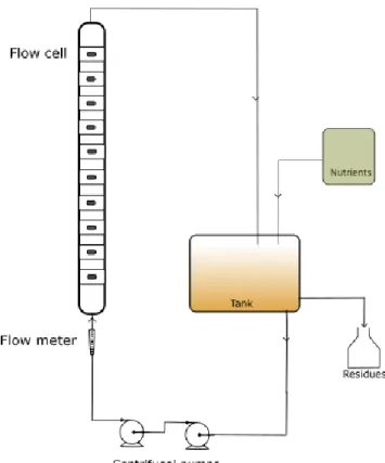
Figure 3.1. Flow sheet of experimental setup of flow cells ………...14
Figure 5.1. Biofilm wet mass per area and biofilm thickness, in coupons of trials A, B, C and D of assays in flow cells, during the process of biofilm formation ………24
Figure 5.2. Biofilm growth, in terms of CFU/cm2, in coupons of trials A, B, C and D of the flow cell assays ………..25
Figure 5.3. Biofilm EPS in trials A, B, C and D, before treatment ………26
Figure 5.4. Culturable bacteria in the planktonic state during the process of biofilm formation ………26
Figure 5.5. Biofilm thickness, during the treatment period, in FC experiments ………..27
Figure 5.6. Biofilm wet mass, during the treatment period, in FC experiments ……….28
Figure 5.7. Biofilm cell density, during the treatment period, in FC experiments ……….28
Figure 5.8. EPS in biofilms, during the treatment period, in FC experiments ………..….29
Figure 5.9. Data obtained by the surface sensor, for DSS1. ……….…….31
Figure 5.10. Data obtained by the surface sensor, for DSS2. ………32
Figure 5.11. Biofilm wet mass in coupons and tube of DSS assays. ……….32
Figure 5.12. Culturable biofilm bacteria in coupons and tube of DSS assays. ………..34
Figure 5.13. Cell viability in coupons and tube of DSS assays. ……….34
Figure 5.14. Total biofilm bacteria in coupons and tube of DSS assays (results from Live/Dead). ………….35
Figure 5.15. EPS, in terms of proteins and polysaccharides, in biofilms of coupons and tube of DSS assays. ……….35
LIST OF TABLES
Table 3.1. Hydrodynamic conditions of the assays in Flow Cells and DSS. ……….….... 19 Table 3.2. Main time points and treatment conditions of assays FC1 and FC2. ……….……….... 20 Table 3.3. Main time points and treatment conditions of assays DSS1 and DSS2. ………..……….…. 20
1. WORK OUTLINE
1.1. Background and research presentation
Biofilms are structured aggregates of bacterial cells that are embedded in self-produced extracellular polymeric substances (EPS)1.
Many industrial environments with large submerged substrata and nutrient fluxes provide ideal conditions for the formation of extensive biofilms. In these systems, biofilms become problematic by causing: (i) increased fluid frictional resistance in pipes; (ii) increased heat energy transfer resistance; (iii) biocorrosion; and (iv) reduced water quality2. Therefore, it becomes critical to achieve microorganisms inactivation and
biofilm removal from the surfaces. If only disinfection takes place, without removal, the inactivated biofilm can constitute an environment conducive for further adhesion and growth3 .
Current techniques used to eliminate or reduce the incidence of biofilm growth include physical and chemical methods. Biocides (intended to kill microorganisms), biostats (control microbial activity) and biodispersants (impose an electric charge either to the substrate or the individual cells or clusters to reduce the possibility of attachment) are employed to reduce the potential for the development of biofilms on equipment surfaces4. Attempts have been made to eliminate surface colonizing microorganisms in
industrial situations through the use of toxic compounds, such as chlorine and other industrial microbiocides. Unlike the situation with planktonic microorganisms, this approach has only limited success when dealing with sessile microbial forms, since considerably higher concentrations of toxic materials are needed. Nevertheless, increasing biocides concentrations is costly, results in increased environmental burdens, and threatens non-target organisms 5. A common treatment involves the combined use
of a biocide and a biodispersant.
Biodispersants are widely used on industrial water treatment applications because of their valuable contribution to systems cleanliness and prevention of biofilm build-up. However, there is little literature describing how they interact with biofilms and surfaces to remove the attached biomaterial.
Chlorine dioxide is a strong oxidant also used in chemical control of microorganisms. Although there are no studies regarding chlorine dioxide biodispersant activity, some companies claim that, besides its biocidal activity, it is also able to remove biofilms6.
Therefore, there is a need to better understand the response of biofilms to exposure to oxidizing biocides and surface-active agents7. The present project aims to go further on
understanding how these chemicals interact with biofilms and how can they be used to improve biofilm control programs.
1.2. Objectives
The aims of this study were: (i) to evaluate the effects of a biodispersant and chlorine dioxide on biofilm removal on stainless steel surfaces; (ii) to understand how these chemicals can act on biofilm density and structure; and (iii) to obtain experimental data that can help to deeply understand the mode of action of these disinfectant agents. Two systems, flow cells, that are widely used in laboratory works, and the Diveil Surface Sensor, an innovative equipment developed by Enkrott, were used for the monitoring of biofilm formation and removal upon chemical treatments. In this work, it was also intended to analyse the parallelisms between the two systems in the study of biofilms. The chemicals chosen for biofilm treatment were a biodispersant, commonly utilized by Enkrott, and chlorine dioxide. Since in many industrial applications biodispersants are commonly used conjointly with biocides, its effect was also studied in combination with the biocide calcium hypochlorite.
1.3. Thesis organization
The present thesis is divided in five chapters.
Chapter 1 is a work outline, including a brief introduction on the topic and research project and the objectives of the developed work.
Chapter 2 presents the literature review with an overview about biofilms, biofouling and most common strategies for biofilm control. Some insights into the chemicals used in
this work, namely chlorine dioxide and some types of biodispersants used in industrial systems, are included here.
In Chapter 3, the experimental set-ups commonly used to form biofilm and test the chemicals antimicrobial action are described, as well as the specific conditions of biofilm formation for each assay.
Chapter 4 comprises the analyses performed, to the biofilms, in order to assess the evolution of some parameters, such as thickness, wet mass, cell density, protein and polysaccharide content, and dry mass. It also accomplishes the analyses of bacterial suspensions.
In Chapter 5, the experimental results obtained in the flow cells and DSS assays are presented.
Chapter 6 presents the main conclusions of this work and some suggestions for future work.
2. LITERATURE REVIEW
In most ecosystems, microbial cells grow on surfaces, with the formation of highly structured sessile microbial communities, called biofilms8. These complex structures
may be related to the earliest life on Earth. Nowadays, most bacteria are thought to form biofilms in nature1.
Surface colonization by microorganisms was first recognized as significant in 19439 and
the term ‘biofilm’ was coined and described in 197810. Since then, it has been recognised
that there are some differences, in terms of the genes that are transcribed, between microorganisms living in biofilms and their planktonic relatives11. A realization that
microorganisms should be studied, not only as biofilms, but also in the context of the biofilms interactions with their immediate surroundings has arisen in the last decades, as well as the influences they exert on the environment. The study of biofilms is relevant to a wide range of areas, and research to understand the interactions occurring between the cells and the adhering surfaces, and also between the microcolonies that coexist within multispecies biofilms, should follow a multidisciplinary approach12.
2.1. Characteristics of biofilms
Initially, the biofilm was defined as a homogeneous distribution of cells in a confluent, blanket-like exopolysaccharide matrix12. Confocal laser scanning microscopy (CLSM) has
been a standard tool for characterizing biofilms in situ, leading to a better understanding of the processes and structures within the biofilm13. Images acquired by CLSM have been
used to decipher biofilm spatial structure, by making it possible to represent the 3-D architecture and to quantify structural parameters such as the biofilm bio-volume, thickness and roughness14. Biofilms are now modelled as microcolonies or clusters of
cells enclosed within a hydrated matrix, with pores or channels throughout the nonconfluent biofilm. The pores and channels facilitate transport of oxygen and nutrients to the microcolonies and removal of waste and secondary products15. Biofilms
optimized arrangement also facilitates the transfer of plasmids enclosing drug and heavy metal resistance, because of the proximity of the cells16. The biofilm matrix of
exopolysaccharide has a postulated role in antimicrobial resistance, possibly acting as an ion exchange resin or ionically hindering the inward diffusion of cationic molecules12.
The biofilm has also been compared to a primitive eukaryotic tissue, with homeostatic control mechanisms and an important level of physiological cooperativity.
2.1.1. Beneficial potential of biofilms
Biofilms have great potential to be used in the biotechnology industry, because they exhibit several capabilities, such as production of specific metabolic compounds and an increased level of performance in a reactor system compared to planktonic bacterial cultures12. Biofilms play a significant role in the biodegradation of organic compounds
and the transformation of inorganic compounds, subsequently acting to minimize the build-up of pollutants. Most sections of the human and animal gastrointestinal tract are colonized by bacteria that form tissue-protective biofilms, preventing adhesion by foreign bacteria.
2.1.2. Detrimental effects of biofilms
Biofilms represent a major concern in industry and hospital healthcare settings where they cause severe structural and health problems13. In biomedical and engineering
systems, they have numerous effects, that lead to increasing financial costs12: (i) physical
damage, e.g., corrosion; (ii) reduction in proper function of the surface, e.g., reduced efficiency of heat exchangers and turbine power losses in hydroelectric pipelines; and (iii) creation of a reservoir of potential pathogens.
Biofilms can promote other fouling mechanisms, such as corrosion, crystallization and retention of particular matter, which has been defined as biofouling17. Biofouling has
also shown several problems on surfaces and surroundings.
As depletion of oxygen occurs by the aerobic microorganisms present in the microbial consortium, anaerobic zones are formed within the biofilm, favouring the growth of
primary corrosion organisms such as the sulphate-reducing bacteria, acid producing bacteria and iron oxidizing bacteria18.
Aggregates of bacteria are at the source of most persistent infections19. Legionella pneumophila, a pathogenic microorganism, has been demonstrated to be
associated with some amoeba species in biofilm communities present in cooling towers and water systems20. Additionally, the contamination of food products may occur
following contact with potentially detrimental bacteria sequestered within surface-associated biofilms21.
2.2. Biofilm formation
Biofilm formation is generally established through several steps1. Firstly, planktonic cells
attach to the surface, in a process that involves electrostatic interactions, hydrogen bonds and London dispersion forces22. Microorganisms can readily attach to a wide
variety of surfaces in a defined series of steps and in a layering progression. The initial colonizers, frequently specific bacteria, are able to adhere due to their ability to produce exocellular polymers, composed primarily of non-ionic and anionic polysaccharides5.
Bacterial adhesion is a complex process that is affected by (i) some characteristics of the surface (texture, roughness, hydrophobicity, surface chemistry and charge); (ii) environmental conditions (temperature, pH, time of exposure, bacterial concentration, chemical treatment or presence of antimicrobials and fluid conditions); and (iii) intrinsic physicochemical characteristics of bacteria (hydrophobicity, surface charge, production of polysaccharides and cell motility)23,24. Once the substratum is
colonised by microorganisms, cells will grow and produce EPS, microcolonies will develop and coadhesion and coaggregation of different bacterial cells will contribute towards the development of a multi-species biofilm25. Cell surface properties, namely
the presence of extra-cellular appendages, the interactions involved in cell-cell communication and EPS production are important for biofilm formation and development. EPS are responsible for adhesion to surfaces, scaffolding cells together, maintaining the tri-dimensional architecture of the biofilm, and protecting the cells against stress conditions. Its components include polysaccharides, nucleic acids,
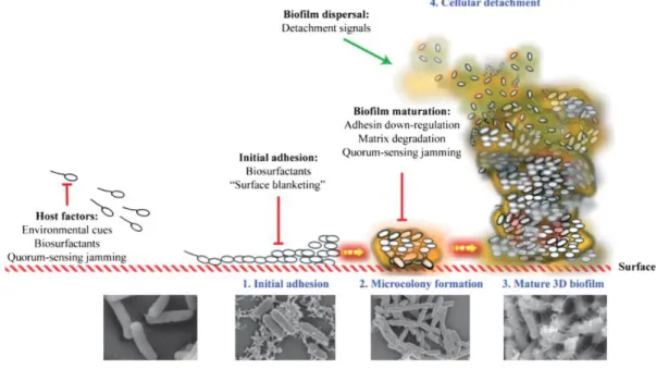
proteins, lipids and other biopolymers. After maturation, the cell leaves the biofilm in the dispersal stage. This process is illustrated in Figure 2.1.
Figure 2.1. Illustration of the process of biofilm formation and scanning electron microscopy images representative of each steps26.
2.3. Strategies for Biofilm Control
Nowadays, it is widely accepted that biofilm bacteria are much more resistant to antimicrobial agents than their planktonic counterparts. Therefore, the control and eradication of biofilms in industry is harder and costly2. Some theories concerning the
mechanism of resistance of bacteria in biofilms to antimicrobial agents include reduced diffusion of materials through the glycocalyx, overproduction of hydrolytic enzymes and concentration of these within the exopolymer matrix, physiological changes due to reduced growth rates and the induction of drug-resistant physiologies27.
Biofilm control can be divided into two areas: (i) the prevention of initial colonization and subsequent biofouling; and (ii) the development of removal/control strategies against the established biofilm12. The equipment design and choice of surface materials
are important in preventing biofilm formation23. The most practical material in
processing equipment is stainless steel, which can be treated with mechanical grinding, brushing, lapping, and electrolytic or mechanical polishing. For an efficient sanitation
programme, the process equipment must be designed with high standards of hygiene in mind. Dead ends, corners, cracks, crevices, gaskets, valves and joints are vulnerable points for biofilm accumulation.
The main strategy to prevent biofilm formation is to clean and disinfect regularly before bacteria attach firmly to surfaces. An effective cleaning and disinfection programme is the main strategy to control surface route contaminations and it must remove undesirable material from the surfaces, including microorganisms, residues, foreign bodies and residual cleaning products. Physical scrubbing and chemical treatment methods are commonly used to mitigate problematic industrial biofilms. These two methods are often combined because physical scrubbing (or pigging in the pipeline industry) alone is often inadequate 18.
Bactericidal compounds, both oxidizing and non-oxidizing, have been used extensively to eradicate or control microbial activity in industrial systems, but due to tighter legislation and the higher level of environmental awareness, industry has been compelled to change its strategy for biofouling control2. Additionally, in any biocidal
treatment, the continued use of the same biocide will inevitably promote resistant microbes18. The oxidizing microbiocides, such as chlorine, bromine, chlorine dioxide,
peracetic acid and ozone can be extremely effective in destroying both the extracellular polymeric substances and the bacterial cells28. Besides choosing the correct biocide, to
reduce the fouling rate, it is essential to apply the correct biocide concentration at the correct frequency. So, for a successful chemical treatment programme, it is important to pre-determine the minimum contact time required for a biocide to kill bacteria29.
It is generally more effective to maintain a higher residual for a duration of several hours than it is to continuously maintain a low residual. Continuous low-level feed may not achieve an oxidant concentration sufficient to oxidize the polysaccharide and expose the bacteria to the oxidant. Most non-oxidizing microbiocides have negligible effect in destroying the extracellular polysaccharide found in the biofilm. However, many of these microbiocides may be able to penetrate and kill bacteria found within the biofilm, resulting in decreases in the population and weaknesses in the biofilm structure. Thus, using the combination of non-oxidizing and oxidizing microbiocides is a very effective method of controlling biofilm. Using combination biocides has proven very successful in
killing unwanted bacterial species, since they show different mechanisms of antimicrobial activity.
Since the killing of biofilm bacteria does not necessarily bring about removal of a biofilm from the surface, the largely dead biofilm could still be detrimental to the system by promoting regrowth and by fouling the surface. Furthermore, generally, disinfectants do not penetrate the biofilm matrix left on a surface after an ineffective cleaning procedure, and thus do not destroy all the biofilm living cells23. Therefore, it is more
important to remove the biofilm completely, rather than killing the cells therein and leaving it on the surface. Thus, industry has moved progressively towards the use of more biodegradable and less toxic compounds, such as surface-active compounds, especially synthetic surfactants, commonly termed dispersants or biodispersants. There are some studies reporting superior effectiveness of chlorine dioxide in the control and removal of biofilms30,31. Additionally, there are companies claiming that, in applications
such as paper manufacture, food processing and cooling water systems, chlorine dioxide is an excellent slimicide and can usually be used alone in situations where both chlorine and a biodispersant were previously required32,33.
2.4. Biodispersants
Biofilm control programs can be made more effective through the use of biopenetrant/dispersant products28. The use of biodispersants in cleaning and
disinfection operations, to enhance the effectiveness of oxidising biocides, is recommended in European guidelines for the control and prevention of Legionnaire’s disease34. The selection of a suitable antimicrobial agent able to penetrate a biofilm is
of utmost importance when developing disinfection plans35. The use of biodispersants
offers an ecologically attractive method of controlling slime, since they eliminate or reduce the needs for biocides. Biodispersants are nonbiocidal surface-active agents that can penetrate the complex network of polymeric chains constituting the matrix of the EPS and pre-condition the growth surfaces36. They dissolve and disperse deposits,
preventing the biofilm from re-establishing itself. This not only aids in sloughing the biofilm but will also expose the microorganisms to the microbiocides. They can be
continuously applied or periodically slug-dosed. Biodispersants are particularly effective when dealing with systems that have a high total organic carbon loading and a tendency to foul. These products are typically fed in slug additions before microbiocide feed. Low-level continuous feed may also be effective. However, in some cases, this may not be as effective because it may not reach a certain threshold amount required to produce the desired effect. This technology is based on nontoxic, nonfoaming, colourless polymers and free of organic solvents. Because these products effectively mobilize solids, they can cause clogging in downstream and down-gradient locations, and this potential must be considered when designing proper application.
Dispersants are classified according to the ionic nature of the hydrophilic group, namely, anionic, cationic, non-ionic and zwitterionic2. These compounds have various
mechanisms of action against microorganisms. Anionic dispersants (e.g. alkyl and aryl sulfonates) reduce cell wall permeability and can dissolve the entire cell membrane, whereas cationic dispersants (e.g. quaternary ammonium compounds, which can also have biocidal properties) adsorb to the surface of the cell membrane and chemically react with the negatively charged ions associated with the cell wall. Dispersants may also alter the surface properties of the submerged surfaces by decreasing the surface tension, thereby either preventing attachment of biofouling organisms to submerged substrata or promoting the detachment of these organisms from the substrata. The chemistry of dispersing agents can be designed to give various dispersing/solubilizing and emulsifying properties to the product, which may disturb the biofilm, stabilize the emulsion with cells and biofilm components, and form a protective layer on the hydrophobic surfaces that delays the attachment of biofilm. Results using a simple screening technique indicated that the non-ionic dispersants worked more effectively than anionic or cationic ones37. Different dispersants chemistries can be designed
according to the proposed use28. The name biodispersant suggests the activity on a
biological entity, but laboratory study has shown that many commercial biodispersants, in the absence of a microbiocide, have little or no ability to remove an existing biofilm or prevent their formation. In fact, most of the commercial biodispersant applications include the use of a microbiocide. Biodispersant technology can increase the overall efficiency of a given microbiocide program.
Dispersants do not kill or do not always even inhibit the growth of microorganisms. Therefore, their dosage or evaluation of their effect cannot be based on cell counts in circulation waters and new efficient methods to evaluate their efficiency in mill conditions are required28.
2.5. Chlorine dioxide
Chlorine dioxide is an oxidising biocide capable of reacting with a wide range of organic substances including many of the constituents of bacterial cells. The primary mechanism for inactivation of bacteria with ClO2 is disruption of the protein synthesis pathway by
inhibition of enzymes or interference with nucleic acid-amino acid complexes38. The low
levels of chlorine dioxide used in drinking water inactivate bacteria due to oxidation, disrupting several different cell processes. In general, it has been shown that levels of chlorine dioxide at 0.5 ppm produce an effective disinfection39. While chlorine is
inexpensive and commonly used in a variety of industrial settings, chlorine dioxide has been described to be more effective than chlorine against biofilms40. Because chlorine
dioxide has different reaction pathways involving natural organic matter than free chlorine, the formation of disinfection by-products (DBPs) like organohalogens is typically much lower in concentration than when using free chlorine41. However,
chlorite is a known by-product of chlorine dioxide generation and it also influences bacterial levels since it has bacteriostatic properties. As one of the promising disinfectants, chlorine dioxide has become widespread as it offers some unique advantages, including its easy operation and maintenance, requirement for a smaller dosage, less reaction time to yield same disinfection effect as Cl2, and effectiveness over
a wide pH range on killing bacteria or deactivating virus42. In addition to its biocidal
efficiency, it was reported that chlorine dioxide has a biofilm-removing effect, which may be noticeable at a concentration of 0.5 ppm ClO2, and that it significantly reduces
biofilm formation at a concentration of 100 ppm ClO2 43. It has been shown that chlorine
dioxide is capable to control biofilm under a variety of conditions and remove biofilm in very difficult to treat cooling towers. Nevertheless, chlorine dioxide may not reach
bacteria deep in a biofilm as a result of multiple resistance factors, such as molecular diffusion limitations, biofilm density and reactive depletion of ClO244.
Despite being considered a promising chemical to remove and control biofilms in water systems, relatively few studies have examined this ability of chlorine dioxide.
3. BIOFILM SET-UP
Two flow cell reactors, vertically placed, operating in a continuous recycling mode, were used for biodispersant effect analysis. This system provided controlled environmental conditions for the study of bacterial adhesion and biofilm development45. Additionally,
it allowed a better observation and characterisation of the biofilm, with the possibility to obtain images of it. Diveil Surface Sensor, used for the study of chlorine dioxide effect, constitutes an advanced strategy as it provides a continuous monitoring of bacterial adhesion and biofilm evolution.
3.1. Flow cells
An experimental set-up with two parallel flow cells, with two similar systems as the one shown in Figure 3.1, was used in this project (see Appendix A.1). The flow cells are similar and consist of semi-circular cross section Perspex (polymethyl methacrylate) ducts (94 cm length and 1.83 cm of hydraulic diameter), with 10 apertures on their flat wall, to suitably fit the several adhesion plates. These plates are made of AISI 316 stainless steel coupons (1 cm × 2 cm and 1 mm thick) glued to rectangular pieces of Perspex that properly fit in the apertures of the flow cell. Their upper faces, where the biofilm is formed, are in contact with the bacterial suspension that circulates in the semi-circular duct. The flow cells are mounted vertically in order to eliminate the effects of gravity on the development of the biofilm in the tubes. The material used to study the adhesion is stainless steel because it is a common industrial material of construction. The sampling was made from the top to the bottom. One piece (from each flow cell) with a rectangular coupon was removed and substituted with a new one, previously cleaned with 70% (w/v) ethanol and dried before insertion into the system.
Two centrifugal pumps arranged in series, for each flow cell, are used to draw off the fouling solution from the tanks and to recirculate it through the system. The flow through the flow cells is controlled and measured by flow meters (rotameters).
The volumetric flow obtained with these conditions is approximately 390 L/h, the velocity is 0.3 m/s and the Reynolds number is 5600 that corresponds to a turbulent flow. Biofilms formed under turbulent conditions tend to have more cells per unit wet volume and they may produce more exopolymers per unit volume to create an effective adhesion and reduce the void fraction in the biofilm to impart a greater cohesion to the biological matrix46. This allows the cells to remain relatively active within the matrix but
protected from external aggressions.
This experimental set-up was used for two independent experiments. The two systems were designated A and B in the first experiment, and C and D, respectively, for the second experiment.
The two systems differ in the total volume: the tank of system A/C has a volume of 5 L and system B/D has 4 L, approximately, being the total volume of each system around 1 L more than the tank volume. Both tanks were suitably aerated and magnetically agitated.
3.2. Diveil Surface Sensor
To study the effect of chlorine dioxide on biofilms, a different experimental set-up was used – Diveil Surface Sensor (see Appendix A.1), developed by Enkrott, which provides information about the attached layers and allows the use of online, in real-time monitoring techniques for fouling phenomenon47. DSS is commonly used for monitoring
fouling phenomenon in water circuits and can also be used to assess the efficacy of the cleaning actions performed. This equipment includes a device that uses a sensor technology based on the analysis of the change on the surface vibration properties caused by the adhesion, growth or detachment of deposits developing on the monitored surface48. DSS has also a biofilm sampling device, which contains multiple removable
cylinders (0.7 cm I.D., 0.9 cm O.D., 3 cm long) constructed of stainless steel material and mounted in line with the main pipe. Additionally, the crystal PVC tube, through which the flow returns to the tank, was used to evaluate the effect of chlorine dioxide on biofilm removal.
The total volume of this system is approximately 20 L and the volumetric flow is around 110 L/h. Consequently, the flow velocity in the cylindrical coupons is 0.8 m/s and in the crystal tube is 0.6 m/s. The Reynolds number are 5540 and 4850, in the coupons and tube, respectively, which assures a turbulent flow. Agitation in the tank was promoted using a centrifugal pump. No aeration was needed since the system was not completely closed to the atmosphere.
3.3. Bacterial strain and growth media
The biofouling solution consists of a monoculture of Pseudomonas fluorescens. This microorganism was chosen for this study as a model bacterium because it is: (i) a well-studied, gram-negative bacterium; (ii) ubiquitous in nature and in industrial environments; (iii) a good biofilm producer; and (iv) with a strong ability to form disinfectant-resistant biofilms49,50.
An inoculum of the P. fluorescens strain was propagated on plate count agar (PCA) after being removed from the cryovial, which was preserved at -80 ºC, in a mixture of nutrient broth and 15 % (v/v) of glycerol. After incubation for 24 h at 27±3 ºC, the necessary volume of growth media (5 g/L glucose, 2.5 g/L peptone and 1.25 g/L yeast extract, in 0.02 M phosphate buffer, pH 7) was inoculated with the colonies obtained. Then, it was incubated overnight at 30 ºC and 100 rpm.
The assays in each system were initiated by adding sterile saline solution till about 87.5 % of the total volume and filling it with the bacterial suspension, approximately 2 h before the beginning of the continuous flowing process. For the flow cells system, sterile nutrient solution, consisting of 50 mg/L glucose, 25 mg/L peptone and 12.5 mg/L yeast extract, in 0.02 M phosphate buffer, pH 7, was fed into the fermenter by a peristaltic pump 50. In the case of DSS, the growth media was four times more concentrated, to
maintain the same nutrient composition in the system, as its volume is approximately four times the volume of flow cell systems. The working volume was maintained constant.
3.4. Disinfectants
The liquid biodispersant and the chlorine dioxide solution used were provided by Enkrott. These products are commonly used by the company in their pre-treatments and disinfection procedures.
The commercially available dispersants are proprietary products and information relating to their chemical composition and biodegradability is not freely available2. The
biodispersant used was analysed in terms of zeta potential and the results showed that its hydrophilic polar group is negatively charged, being classified as anionic biodispersant.
3.5. Specific conditions of the assays
Before biofilm formation, the systems were cleaned and disinfected with commercial detergent and bleach, by circulation of these solutions. Afterwards, in order to remove any remaining detergent and bleach, the cleaning solutions were removed and distilled sterile water circulated in the system.
For each system, two independent experiments were performed (Flow Cell 1 - FC1, Flow Cell 2 - FC2, Diveil Surface Sensor 1 - DSS1 and Diveil Surface Sensor 2 - DSS2). The biofilms were grown for 19-20 days in the flow cells and 22-27 days in the DSS, till the system reached the steady state. The preferred strategy for chemical treatments was the method of intermittent dosing, usually designed to minimise colonisation of exposed surfaces by microorganisms4.
In the FC1 experiment, both systems A and B were continuously fed with 400 mL/h of a nutrient solution, like it was done in a preliminary work. Before starting the treatment with biodispersant, at day 20, half of the bulk volume was removed and replaced by saline solution, to decrease the cell density in the planktonic state and avoid biodispersant reaction with culture medium components. The biodispersant was dosed at 10 ppm, which entailed adding an initial shock of 10 ppm on the first day, and thereafter, 5 ppm every 7 hours (half-concentration time) to maintain 10 ppm. From day 26 to the end of the assay, the biocide calcium hypochlorite (CH) was also dosed at 1 ppm, simultaneously with the biodispersant. However, from day 28, the frequency of the shocks increased to every 3 hours, since the first strategy was not producing any effect on the biofilms. This treatment strategy continued until day 37.
In the FC2, the flow rate of nutrient feed of system D was reduced, to 340 mL/h, to achieve the same dilution rate used in system A, since biofilm formation in system A was greater than in system B and, therefore, its removal was more challenging. During this assay, nutrient feed was replaced by saline solution upon the beginning of biodispersant dosing, at day 19. Additionally, CH simultaneous dosing, started at day 27, every 7 hours. At day 36, BDP and CH were added in a shock of about 260 ppm and 50 ppm, respectively. The system was monitored till day 42.
In the first assay in DSS (DSS1), the system was continuously fed with nutrient solution at 400 mL/h. The biofilm achieved the steady state after 21 days, when 15 L of bulk volume was replaced by saline solution. At day 22, the treatment started with an initial shock of 5 ppm of ClO2 and it continued with 1 ppm shocks every 3 hours. Since ClO2 is
a very strong oxidant agent and is rapidly consumed, the addition of biocide was more frequent to maintain a residual disinfectant concentration in the system. Chlorine dioxide addition was stopped at day 32. From day 35 to the end of the assay, there was no nutrient feed income in the system and the monitoring finished at day 40.
In the DSS2 experiment, the treatment started with an initial shock of 5 ppm and ClO2
was dosed, at 2 ppm every 3 hours, from day 27 to day 35. When the treatment began, the nutrient feed was replaced by saline solution.
Tab le 3 .1 . H yd ro d yn amic co n d itio n s o f t h e a ss ay s in Flo w C ells a n d DSS. DSS 2 Tu b e 11 0 L/ h 0 .6 m/ s 4850 20 L 40 0 mL /h 0 .02 h -1 C ou p o n 0 .8 m/ s 5540 DSS 1 Tu b e 0 .6 m/ s 4850 C ou p o n 0 .8 m/ s 5540 FC2 D 39 0 L/ h 0 .3 m/ s 5600 4 .86 L 34 0 mL /h 0 .07 h -1 C 5 .95 L 40 0 mL /h FC1 B 4 .86 L 400 mL /h 0.08 h -1 A 5 .95 L 0 .07 h -1 V o lu met ri c flo w (Q ) Flow v eloc it y (v) Reyno ld s (R e) Tot a l sy st em vo lu me (V) Fe ed v o lu met ri c flo w D ilu tio n ra te
Tab le 3 .2 . M a in t im e p o in ts an d t re atm en t co n d ition s o f assay s FC1 an d FC2. FC2 D ay 1 9 N u trient fee d re p laced b y salin e sol u ti on D ay 2 7 D ay 3 6 – s h ock of 2 6 0 p p m B D P + 5 0 p p m C H D ay 4 2 FC1 D ay 2 0 Kee p n u trie n t fe ed D ay 2 6 D ay 3 7 St a rt B D P trea tmen t (1 st sh o ck 10 p p m + 5 p p m ev ery 7 h o u rs) Ad d b io cid e CH t o t h e tre a tmen t (1 p p m) End o f a ssay Tab le 3 .3 . M a in t im e p o in ts an d t re atm en t co n d ition s o f assay s D SS 1 an d DS S2. DSS 2 D ay 2 7 – in it ia l sh ock of 5 p p m + 2 p p m ever y 3 h ou rs N u trient fee d re p laced b y salin e sol u ti on D ay 3 5 D ay 4 2 DSS 1 D ay 22 – in it ial sh ock o f 5 p p m + 1 p p m ever y 3 h ou rs Kee p n u trie n t fe ed Day 3 2 D ay 3 5 – s top f ee d D ay 4 0 Sta rt C lO2 tr eat m en t Sto p C lO2 d o sin g End o f a ssay
4. BIOFILM AND BULK ANALYSES
Disinfection and biofilm removal efficiencies were assessed through periodical analyses of biofilm in the stainless-steel coupons and in the crystal tube (only DSS) and also of samples of the bacterial suspension in the tanks.
4.1. Biofilm characterization
Biofilms were characterized in terms of thickness, wet and dry mass, culturable and total cells, cell viability and EPS content51.
4.1.1. Thickness
Biofilm thickness was determined using a digital micrometer (VS-30H, Mitsubishi Kasei Corporation). For each sample, a mean value was determined out of 10 measurements at different points in the coupon. This parameter was only evaluated for biofilms in the flow cells, since the analysis was impossible to perform in the cylindrical coupons of DSS.
4.1.2. Wet mass
Immediately after being removed from the flow cell, the mass of the coupon and its support piece with biofilm was measured. After this, the biofilm was removed from the coupon using a stainless-steel scrapper. The supporting piece with the coupon was left in a desiccator to dry and weighted. Biofilm wet mass was obtained as the difference between these two values.
4.1.3. Cell density
The biofilm removed from the coupon was resuspended in 10 mL of extraction buffer (0.76 g/L Na3PO4.H2O, 0.36 g/L Na2HPO4.H2O, 0.53 g/L NaCl, 0.08 g/L KCl). After that, the
bacterial suspensions on PCA, using the motion drop method 52, the necessary dilutions
were performed in saline solution at 0.85 % (w/v). The plates were incubated at 30 ºC for 24 h and cultivable bacteria were quantified, in terms of CFU per mL (CFU/cm2), by
counting the colonies on the plates.
Viable and non-viable cells were assessed using the Live/Dead BacklightTM kit
(Invitrogen). This procedure couples green SYTO-9 (cell permeant) and red propidium iodide (cell impermeant) so that bacteria with a compromised membrane appear yellow or red, while the live viable cells (with intact cell membranes) fluoresce green14. The
1 mL aliquots of samples were stained, with 250 µL of Reagent A (SYTO 9) and 50 µL of Reagent B (propidium iodide), and incubated in the dark at room temperature for 7 minutes. Afterwards, the stained sample was filtered through a 0.2 µm Nuclepore filter, and the filter was mounted in Backlight mounting oil. The samples were observed in a fluorescence microscope (Leica) and the results expressed in terms of cells/cm2.
4.1.4. Proteins and polysaccharides content
The total and extracellular polymeric substances were quantified in terms of proteins and polysaccharides content. EPS were extracted with Dowex® Marathon© resin (NA+
form, strongly acidic, 20-50 mesh, Sigma). In a 20 mL beaker, 0.5 g of the resin were added to 5 mL of biofilm suspension and the extraction was performed at 400 rpm and 4 ºC for 4 h. The extracellular components, present in the supernatant, were separated from cells through centrifugation (16800 g, 6 min). The biofilm proteins were quantified by the Pierce method (BCA Protein assay, Thermofisher Scientific) using bovine serum albumin as standard. The polysaccharides were quantified using the phenol-sulphuric acid method using glucose as standard53.
4.1.5. Dry mass
The dry biofilm mass was assessed by determination of the dry mass (after 24 h at 105 ºC) and total volatile solids (after 2 h at 550 ºC). The biofilm mass was expressed in mg of biofilm per cm2 of surface area of coupons.
4.2. Bacterial suspension analyses
Some variables can influence biofilm growth, such as microbial concentration, pH and saturation level of oxygen, and should be carefully monitored54. So, as well as for biofilm,
some analyses were performed for the culture in the tanks. At the same time points, samples from the tanks were collected to measure pH and dissolved oxygen. Analyses to bacterial density in planktonic state were also performed, using the same techniques described in section 4.1.3.
5. RESULTS AND DISCUSSION
5.1. Flow cells
The effect of biodispersant on biofilms was assessed in the assays FC1 and FC2, which resulted in 4 trials, A and B from FC1 and C and D from FC2.
5.1.1. Biofilm formation
In the flow cells, biofilm growth was monitored by coupon periodically sampling. The system surfaces (including stainless steel coupons) quickly became colonized, with a steady-state biofilm being established within 2 or 3 weeks, which is consistent with biofilm work of others41.
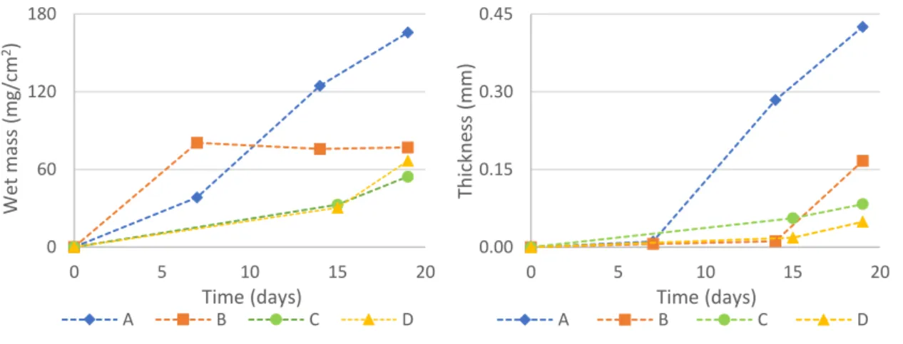
In terms of biofilm wet mass and thickness, in trials B, C and D, the values right before beginning of treatment were very similar (Figure 5.1). In trial A, the biofilm formed was much thicker, which might have been influenced by several factors, such as the lower dilution rate (compared to trial B). In the assay FC2, the dilution rate of trial D was adjusted to obtain the same value, for both trials, as in trial A. With this procedure, it was expected that biofilms in trials C and D achieved similar levels to biofilm A. However, this was not verified.
Figure 5.1. Biofilm wet mass per area and biofilm thickness, in coupons of trials A, B, C and D of assays in flow cells, during the process of biofilm formation.
0 60 120 180 0 5 10 15 20 Wet mas s (m g/cm 2) Time (days) A B C D 0.00 0.15 0.30 0.45 0 5 10 15 20 Th ickn es s (m m ) Time (days) A B C D
In each assay, FC1 and FC2, the biofilm growth curves of the two trials have similar behaviours, in terms of culturable bacteria (Figure 5.2). However, in trial B biofilm cell areal density (CFU per cm2) is quite lower than in A, which may be due to a slightly higher
dilution rate. The biofilms from trials C and D were also less colonized. Right before beginning the treatments, biofilm bacteria levels ranged between 7.5 × 10⁴ and
6.8 × 10⁶ CFU/cm2 in the flow cell assays.
Figure 5.2. Biofilm growth, in terms of CFU/cm2, in coupons of trials A, B, C and D of the flow cell assays.
Despite biofilm A being thicker and the surface area covered being bigger than biofilm B, the cell density (per cm2) was similar in both biofilms (≈ 107 CFU/cm2), right before
beginning biodispersant treatment. Then, it seems that these biofilms differ mainly in the amount of EPS (Figure 5.3). In fact, these assays seem to indicate that lower dilution rates favour higher production of EPS, since smaller quantities of EPS were found in biofilm B. 1E+00 1E+02 1E+04 1E+06 1E+08 0 5 10 15 20 C ell d en sity (C FU /c m 2) Time (days) A B C D
Figure 5.3. Biofilm EPS in trials A, B, C and D, before treatment.
Despite the observed differences between biofilms of the four trials, all the systems provided conditions that favoured biofilm formation under turbulent flow, as verified in the results presented above and shown in biofilm images (see Appendix A.2). Additionally, a reduction, ranging between 1 and 2 log, in planktonic bacteria was observed, which may be associated with biofilm formation (Figure 5.4).
Figure 5.4. Culturable bacteria in the planktonic state during the process of biofilm formation.
0 10 20 30 40 50 10 12 14 16 18 20 [Pro teins +Po ly sacch ar id es ] (m g/ g b iof ilm ) Time (days) A B C D 1E+04 1E+05 1E+06 1E+07 1E+08 1E+09 0 5 10 15 20 CF U /m L Time (days) A B C D
5.1.2. Biodispersant effects
The biodispersant was applied when a steady-state biofilm was established. Then, the disinfection period lasted approximately 2-3 weeks. The evolution of biofilm thickness, wet mass, culturable bacteria and EPS, during the treatment period, is presented in Figures 5.5 to 5.8.
Figure 5.5. Biofilm thickness, during the treatment period, in FC experiments (FC1 – A and B; FC2 – C and D). Calcium hypochlorite was added at day 6 for A and B, and at day 8 for C and D; a shock (260 ppm BDP + 50 ppm CH) was applied at day 16 in FC2. 0.00 0.10 0.20 0.30 0.40 0.50 0 5 10 15 20 25 Th ickn es s (m m )
Time after treatment beginning (days)
A B C D
+CH (FC1)
+CH (FC2)
Figure 5.6. Biofilm wet mass, during the treatment period, in FC experiments (FC1 – A and B; FC2 – C and D). The arrows indicate the day when calcium hypochlorite was added, for each assay.
Figure 5.7. Biofilm cell density, during the treatment period, in FC experiments (FC1 – A and B; FC2 – C and D). The arrows indicate the day when calcium hypochlorite was added, for each assay.
0 25 50 75 100 125 150 175 0 5 10 15 20 25 Wet mas s (m g/cm 2)
Time after treatment beginning (days)
A B C D 1E+2 1E+3 1E+4 1E+5 1E+6 1E+7 1E+8 1E+9 0 5 10 15 20 25 Ce ll d en sity (CFU /cm 2)
Time after treatment beginning (days)
A B C D +CH (FC1) +CH (FC2) +CH (FC1) +CH (FC2)
Figure 5.8. EPS in biofilms, during the treatment period, in FC experiments (FC1 – A and B; FC2 – C and D). The arrows indicate the day when calcium hypochlorite was added, for each assay.
Two days after beginning biodispersant treatment, biofilm A registered decreases in thickness, culturable bacteria and, in a greater extent, in wet mass and amount of EPS. However, this tendency of biofilm reduction was not prolonged in the following weeks and the biofilm was able to recover. The biodispersant may have changed the structure of the biofilm matrix, which, in turn, may have increased the oxygen diffusion and availability of nutrients to the cells embedded in the biofilms, promoting bacterial recovery55.
In biofilm B, although thickness, wet mass and EPS levels increased in the first days, in the succeeding weeks thickness and wet weight rapidly decreased and remained at low levels. In both trials of FC1, although the addition of the biocide CH, at 1 ppm, may have affected bacteria, decreasing culturable bacteria, it did not promote any biofilm removal effects. This was probably because a minimum free chlorine residual was not continuously maintained, since it was quickly consumed by the organic matter from the nutrient feed. Besides this, particularly in biofilm A, the penetration of biocide into the biofilm matrix was probably not facilitated by the biodispersant, since biofilm thickness was not reduced. After biocide addition, at day 6, the amount of EPS increased, which may have helped biofilm bacteria recovery. The increase of BDP+CH dosing frequency, 8 days after treatment beginning, did not have any effect in biofilm removal.
0 10 20 30 40 50 60 70 0 5 10 15 20 25 [Pro teins +Po ly sacch ar id es ] (m g/g b iofil m )
Time after treatment beginning (days)
A B C D
+CH (FC1)
+CH (FC2)
Despite the differences between biofilm A and B, there is a trend in the evolution of cell density. So, even being in different biofilms, bacteria showed a similar response to the same stimuli.
In the experiment FC2, before the beginning of treatment, biofilms C and D were thinner than A and B. Apparently, in the first 8 days of treatment, biodispersant alone did not have any effect on removing biofilm. Comparing results of day 0 with day 8 of treatment, there was no reduction of biofilm wet mass and, increasing thickness and cell density were even observed in biofilms C and D, respectively.
In this assay, the biocide, added at day 8, could reach, at least the first top layers of the biofilm. Although there was no significant reduction either in biofilms wet mass or thickness, some bacteria might have been affected, resulting in a decrease in culturable bacteria. However, it is not clear that it was the biodispersant that allowed biocide penetration into the biofilms, since these biofilms were thinner than the first ones (A and B) and the nutrient feed was supressed when the treatment began, which could have also fragilized biofilm structure. The shock of 260 ppm of BDP and 50 ppm of CH, after 16 days of treatment, promoted biofilm removal. Biofilm thickness was highly reduced, as well as EPS and cell density. Consequently, cell density in the planktonic state increased, suggesting the detachment of cells from the biofilm to the bulk.
The occurred phenomena may suggest that low concentrations of biodispersant do not promote effective biofilm removal. In previous studies, concordant biofilm responses to surface-active agents were found. It was even suggested, when studying the effect of the anionic surfactant SDS (sodium dodecyl sulphate) on biofilms, that low concentrations can promote the strength of the biofilm structure49. This chemical, that
may affect the mechanical stability of biofilms by disrupting hydrophobic interactions involved in cross-linking the biofilm matrix, only produced effects for high concentrations. This observation may justify the increases in biofilm wet mass, thickness and cell density, during the treatment period, observed in this study.
5.2. DSS
The Diveil Surface Sensor includes an actuator, which stimulates the monitoring stainless steel surface, causing vibrations on it, and a sensor that captures the system vibrating response56. The vibration characteristics of the acoustic wave propagated
along the monitoring pipe is changed according to the biofilm layers attached to the inner surface.
DSS was used to assess the effects of chlorine dioxide on biofilms (no biodispersant was present), in two assays, DSS1 and DSS2. Both assays were performed with the same hydrodynamic conditions. Biofilm accumulation on stainless steel surfaces was continuously monitored through the data acquired by the surface sensor (Figures 5.9 and 5.10).
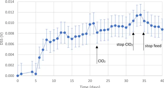
Figure 5.9. Data obtained by the surface sensor, for DSS1.
0.000 0.002 0.004 0.006 0.008 0.010 0.012 0.014 0 5 10 15 20 25 30 35 40 DSS (V) Time (days) ClO2
Figure 5.10. Data obtained by the surface sensor, for DSS2.
Despite the biofilm growth curves having different behaviours, the biofilms established at similar levels. According to this data, ClO2 did not promote biofilm detachment from
the surfaces, since the signal remained relatively stable during all the assay. However, after stopping ClO2 dosing, DSS2 demonstrated a slight reduction of biofilm. In DSS1, a
decreasing tendency in DSS signal was also observed after stopping nutrient feed.
Figure 5.11. Biofilm wet mass in coupons and tube of DSS assays (↑ used for DSS1, ↓ used for DSS2).
0.000 0.002 0.004 0.006 0.008 0.010 0.012 0.014 0 5 10 15 20 25 30 35 40 DSS (V) Time (days) 0 20 40 60 0 5 10 15 20 25 30 35 40 45 We t m as s (m g/ cm 2) Time (days)
Coupon 1 Coupon 2 Tube 1 Tube 2
ClO2 stop ClO2 ClO2 ClO2 stop ClO2 stop ClO2
Regarding biofilm wet mass (Figure 5.11), lower levels were found comparing to the flow cells because these biofilms were formed under lower flow velocities and lower shear stress57. The biofilms showed similar levels of wet mass, right before beginning of
chemical dosage, for all the analysed surfaces, except for the stainless-steel coupons in the second assay (Coupon 2). Higher biomass levels were found here and no reasonable explanation for this phenomenon was found, since the same conditions were maintained. More experiments should be performed to investigate biofilm formation in the cylindrical coupons and relate it to the data from the sensor. These results confirm that ClO2 did not have biofilm removal effect. In fact, it was observed during the
experiments that, when ClO2 was dosed to the system, the turbidity of the bacterial
suspension decreased, suggesting that surface attachment was favoured. However, it appears that after stopping ClO2 dosing small portions of biofilm were detached, since
there was a tendency of wet mass reduction. This may suggest that ClO2 can contribute
to biofilm stability, being consistent with the findings of Shemesh, et al. 58. They showed
that sublethal doses of ClO2 accelerate biofilm formation, by inducting expression of the
genes involved in matrix production. Data from DSS signal is also consistent with this idea, since the signal increased during both ClO2 dosing periods.
In terms of culturable bacteria (Figure 5.12), the biofilms in stainless-steel coupons and in crystal tubes, for each experiment, had similar behaviours. Cell viability (Figure 5.13) correlates with the results of culturable bacteria. When the treatments started, biofilm bacterial levels ranged from 2.9 × 10⁶ to 1.2 × 10⁷ CFU/cm2 in the coupons of these
assays. In the first assay, there was no significant reduction either in culturable bacteria or in total bacteria (Figure 5.14), and cell viability could be recovered within few days, meaning that ClO2 had neither biocidal nor biofilm removal effect. In this assay, the
nutrient feed was maintained during the treatment and the doses of ClO2 applied were
lower. Therefore, ClO2 would be rapidly consumed and was not able to act effectively
on the biofilm.
In DSS2, during the one-week dosing period, a 4-log reduction was observed in biofilm culturable bacteria and 60 % reduction in cell viability. However, after stopping ClO2
dosing (at day 35), biofilm bacteria could recover and achieve the initial levels (≈ 107 CFU/cm2; ≈ 90 % viable cells), in nearly one week. Nevertheless, regarding total
effective killing biofilm bacteria, meaning that it might have been able to enter the biofilm, but it was not able to promote efficiently biofilm detachment.
Figure 5.12. Culturable biofilm bacteria in coupons and tube of DSS assays (↑ used for DSS1, ↓ used for DSS2).
Figure 5.13. Cell viability in coupons and tube of DSS assays (↑ used for DSS1, ↓ used for DSS2).
1E+01 1E+02 1E+03 1E+04 1E+05 1E+06 1E+07 1E+08 1E+09 0 5 10 15 20 25 30 35 40 45 CF U /cm 2 Time (days)
Coupon 1 Coupon 2 Tube 1 Tube 2
0 20 40 60 80 100 0 5 10 15 20 25 30 35 40 45 Viab le ce lls (% ) Time (days)
Coupon 1 Coupon 2 Tube 1 Tube 2
ClO2 ClO2 stop ClO2 stop ClO2 ClO2 ClO2 stop ClO2 stop ClO2
Figure 5.14. Total biofilm bacteria in coupons and tube of DSS assays (results from Live/Dead) (↑ used for DSS1, ↓ used for DSS2).
Figure 5.15. EPS, in terms of proteins and polysaccharides, in biofilms of coupons and tube of DSS assays (↑ used for DSS1, ↓ used for DSS2).
In DSS2, the reduction of biofilm wet mass, after day 38, correlates to the reduction of EPS (Figure 5.15). In this assay, ClO2 dosing was finished at day 35. So, on day 38, there
was no ClO2 present in the system. This evidence reinforces the idea that when ClO2
dosing is stopped, biofilm stability may be more affected, and it starts to detach its top layers. However, in this experiment, the nutrient feed was removed on day 27, upon the beginning of treatment, and this also may have contributed to fragilize the biofilm.
1E+7 1E+8 1E+9 0 5 10 15 20 25 30 35 40 45 To ta l ce lls (c ells /cm 2) Time (days)
Coupon 1 Coupon 2 Tube 1 Tube 2
0 75 150 225 300 375 450 0 5 10 15 20 25 30 35 40 45 [Pro teins +Po ly sacch ar id es ] (m g/g b iofil m ) Time (days)
Coupon 1 Coupon 2 Tube 1 Tube 2
ClO2 ClO2 stop ClO2 stop ClO2 ClO2 ClO2 stop ClO2 stop ClO2
5.3. Bacterial suspension analyses
Regarding the pH of the bacterial suspensions, no significative variations were observed, and the values ranged between 6,3 and 7,7 for all the experiments. The oxygen concentration also remained stable, between 4,0 and 6,8 mg/L, and no tendencies on the evolution of these parameters were observed.
6. CONCLUSION
The systems presented in this work provided an approach to investigate the influence of distinct types of chemicals, currently used in water treatment, regarding the prevention of biofilm layers in water systems. The experiments performed allowed assessing the effect of biodispersant and chlorine dioxide treatments.
Although it was possible to form biofilm in all the experiments within 2-3 weeks, they differ from each other, mainly in terms of thickness and wet mass.
Two experiments in flow cells, that resulted in four trials, were performed to study the effect of a biodispersant. In the first experiment (FC1), no biofilm removal effect was observed, even when the biodispersant was used in combination with the biocide CH and when the dosing frequency was increased. In the experiment FC2, it was found that biodispersant alone did not promote biofilm detachment. However, upon dosing 260 ppm of BDP and 50 ppm of CH to the system, biofilm was effectively removed from stainless steel coupons. The observed phenomena suggest that low concentrations of biodispersant may not promote effective biofilm removal.
The Diveil Surface Sensor allowed continuous monitoring of biofilm in stainless steel cylindrical surfaces. It was used to assess the effects of chlorine dioxide on biofilms, in two independent experiments. The results showed that ClO2 dosing did not have biofilm
removal effect, since no reductions in DSS signal, biofilm wet mass and total bacteria were observed. However, after stopping ClO2 dosing, DSS signal slightly decreased, as
well as biofilm wet mass. The registered effects may suggest that ClO2 can contribute to
biofilm stability, which is in accordance with previous findings regarding the influence of ClO2 in expression of genes involved in matrix production.
In this study, biofilms showed different responses to the treatments. Thus, to attest the observed effects and to better understand how these chemicals interact with biofilms, it is needed to test more conditions and perform different analyses to the biofilms.