Pr.oc:eedings of lntelinational Gonfer.enc:e
er.ague,
1 j 9-~0
Eebr-uar.y 2009
Temperature, oc
Time. SBmn
Temperature, °C
Proceedings
of International Conference
in Prague, 19-20 February 2009
APPLICATIONS
OF STRUCTURAL FIRE ENGINEERING
eurofiredesign.fsv.cvut.cz
Proceedings of International Conference Applications of Structural Fire Engineering
hold during the Czech Presidency of the Council of the EU In Prague, 19-20 February 2009
eurofiredeslgn.fsv.cvut.cz
The preparation of the Proceedings was supported by the research cenlre of the Minis fly of education, youth and sports CIDEAS No. 1 M0579 and the Researth plan Sustainable construcUon No.
684onooo5.
The Illustrative figures on the cover prepared by Nuno R.R. Almelda represent the opportunity of colleagues from Czech Technical University In Prague, University In Colmbra and Slovak Technical University In Bralislava to work on the seventh large fire test In Carding Ion.Ed. Wald F., Kallerova P., Chlouba
J.
ISBN 978-80-01-04266-3
Contents
Preface ... 11 Burgess 1.., United Kingdom
Twenty two years of structural fire engineering in Czech Republic ... 13 R. Kniscr, F. Wald, Czech Republic
Session 1: Case studies
Visible steel for a fire safe structure, case study office building "Junghof" ... 18 Lange J., Ewald K., Germany
Structural fire analysis for a perimeter braced-frame structure ... 22 Jowsey A., Lim. L., Lane B., United Kingdom
Simulation and study of natural fire in a wide-framed multipurpose hall with steel roof truss ... 28
Pada D., Finland
An innovative approach to design fires for structural analysis of non-conventional
buildings, a case study ... 34 Stem-Gottfried J., Rein G., Lane B., Torrcro J.L., United Kingdom
Evaluation of the fire resistance of a sport ball using structural fire engineering ... 41 Vila Real P., Lopes N., Portugal
Design of cold-formed stainless steel tubular columns at elevated temperatures ... 47 To E.Ch.Y., Young B., Hong Kong
Application of structural fire engineering to the steelwork design of Cannon Place, London. 53 Ding S.J., Harries D., Hermouet E., United Kingdom
Session 2: Fire modelling
Fire scenario and structural behaviour of underground parking lots exposed to fire ... 60 Bamonte P., Felicetti R., Italy
Definition and selection of design fire scenarios ... 66 Gkoumas K., Crosti Ch., Giuliani L., Bontempi F., Italy
Generalised thermal and structural fire analysis with GENISTELA and GENISTRUC ... 72 Liang H., Welch S., Faure L., Gillie M., United Kingdom
Experimentation of the subway smoke control system ... ... 78
Ni Z, Kan Q., P. R. of China
Experimental study on baggage fires of subway passenger ... 84 Kan Q., Ni Z., P. R. of China
Numerical simulation on vertical fire spread, effects of wall pier and overhanging eave
in preventing vertical fire spread ... 90
Huang X., Ni Z., Lu S., P. R. of China
Decrease in fire load on structures by timely fire detection ... 96
Dudacek A., Czech Republic
Adiabatic surface temperature, a sufficient input data for a thermal model ... I 02
Sandstrom J., Wickstrom U., Veljkovic M., Sweden
Session 3: Material modelling
Materia] properties loss offibred-SCC due to fire action ... 1 10
Alonso C., Rodriguez C., Spain
Vnriances of steel strength characteristics in fire temperatures ... 116
Domanski T., Poland
Fire damage of stone structures ... ... 122
Hajpal M., Hungary
Thermal characteristics measurements of an inorganic intumescent coating system ... 128
Choi
J.Y.,
Jang H.M., Chun Ch., KoreaStress-strain relationship of reinforcing steel, subjected to tension and high temperature ... 134
Abrnmowicz M., Kowalski R., Poland
Decomposition of intumescent coatings: comparison between numerical method and
experimental results ... ... 140
Mesquita L.M.R., Piloto P.A.G., Va:z M.A.P., Pinto T.M.G., Portugal
Thermal behaviour of alkali activated slag composites: effect of aggregates ... 146
Rovnanik P., Bayer P., Rovnanikova P., Czech Republic
Thermal conductivity of gypsum at high temperatures, a combined experimental and
numerical approach ... 152
Rahmanian I., Wang
Y.,
United KingdomThermal conductivity of gypsum plasterboards, at ambient temperature and exposed
to fire ... 158
de Korte A.C.J., Brouwers H.J.H., The Netherlands
Effective characteristics of fire protection materials ... 164
Application of Structural Fire Design, 19-20 February 2009, Prague, Czech Republic
DECOMPOSITION OF INTUMESCENT COATINGS: COMPARISON BETWEEN NUMERICAL METHOD AND EXPERIMENTAL RESULTS
Lufs M.R. Mesquitau, Pnulo A.G. Pilotou, Mano A.P. Vazb and Tiago M.G. Pintou
• Polytechnic Institute of Brngan~a, Applied Mcchnnics Deportment, Portugal. b University ofPorto, Faculty of Engineering, Portugal.
INTRODUCTION
Passive fire protection materials insulate steel structures from the effects of the elevated temperatures that may be generated during fire. They can be divided into two types, non-reactive, of which the most common types are boards and sprays, and reactive, being intumescent coatings an example. They are available as solvent or water based systems applied up to approximately 3[mm]. One problem associated with the use of such systems is the adhesion of the charred structure to the steel element during fire and upon it. It is very important that the char remains in the steel surface to insure the fire protection.
The intumescent chemistry has changed little over the past years and almost all coatings are largely based on the presence of similar key components. The chemical compounds of intumescent systems are classified in four categories: a carbonisation agent, a carbon rich polyhydric compound that influences the amount of char formed and the rate of char formation; an acid source, a foaming agent, which during their degradation release non-flammable gases such C02 and NH3, [1]. Activated by fire or heat, a sequential chemical reaction between several chemical products takes place. At higher temperatures, between 200-300 [0
C], the acid reacts with the carboniferous agent. The formed gases will expand, beginning the intumescence in the form of a carbonaceous char. Different models handle the intumescent behaviour with char fanning polymers as a heat and mass transfer prol;llem. Other existing models provide a suitable description regarding the intumescence and char formation using kinetic studies of thermal degradation, accounting the complex sequence of chemical reactions, thermal and transport phenomenon, [[2]-[5]].
Due to the thermal decomposition complexity of intumescent coating systems, the models presented so far arc based on several assumptions, being the most relevant the consideration of one-dimensional beat transfer through material, temperature and space independent thermal properties and the assumption of a constant incident heat flux where the heat losses by radiation and convection are ignored, [3). Some authors also assume that the thermochemical processes of intumescence occur without energy release or energy absorption, [6]. Results show that the insulation efficiency of the char depends on the cell structure and the low thermal conductivity of intumescent chars result from the pockets of trapped gas within the porous char which act as a blowing agent to the solid material.
The authors, in a previous work, considering the results obtained from coated steel plates tested in a cone calorimeter studied the intumescence as one homogenous layer. The steel temperature variation was considered and with the intumescence thickness time variation an inverse one-dimensional heat conduction problem (IHCP) was applied to determine the intumescence effective thermal conductivity and thermal resistance [7].
This work presents an experimental study to assess the performance of water-based intumescent paints used as a passive fire protection material. These tests were performed in a cone calorimeter, in steel plates coated with two different paints, three dry film thicknesses and considering two different radiant heat fluxes. During tests, among other quantities, the steel temperature, the intumescence mass loss and thickness variation were measured. A numerical model is also presented to study the intumescence behaviour. The paint thermal decomposition numerical model is based on the conservation equation of energy, mass and momentum.
1. EXPERIMENTAL TESTS PERFORMED IN THE CONE CALORIMETER
To assess the performance of two commercial water-based intumescent paints a set of experimental
tests was performed in a cone calorimeter, see Fig. 1 and Fig. 2. The steel plates are 100 (mm] squared and 4, 6 [mm] thick, coated in one side with different dry film thicknesses and tested in a cone calorimeter as prescribed by the standard 1805660, [8]. Temperatures are measured by means of four thermocouples, type k, welded at the plate in the heating side and at the opposite side, at two different positions. The samples were weighted before and after of being coated allowing for the initial coating mass. The dry thickness was also measured in 16 different points, being the mean values and the standard deviation presented in the Fig. 1.
liiUI21~ililljlill%i
:~~I
Mi
m;ll!lt~lil~ljliJ~
Imil
m
I m lllil
.M
E
1
uu1:
l!il
u
m~ ~~~:iH
U!l
1
:m
un1
lcliililtii~IS:YI:Eilllnl
~!n llUII*Illl!l~lilill:ui:&Mii~H
I
~~ S
I!!JI
Jw.n :W07
1 ~M UQitl l 909 ""
....
~ ~Mnn ~ 4 , ,
~ ~ 1 191>1 410 '10
D " 4 'U • 9
!li 6 ,..,9 n.a ~ 0
•
•Fig. I. Set of cxperimentnl tests. Reference: Pnint/Hent Flux/Steel Thick./Dry Thickfl"est N°.
"""'"
....
_.
__
__
--·--Fig. 2. Couterl steel plutes, with fixed thennocouples. Tested samples nt 35 [kW/m2] nnd at 75 [kW/m2]. Reference nnd position of the thcnnocouples.
Between the steel plate and the sample older two silicate plates were used to put the specimen in place and also a thermocouple was placed to measure its temperature variation. The distance between the sample surface and the heater remained unchanged, at approximately 60 [mm], which means that with the increasing intumescence the top of the sample came closer to cone surface. Due to the large amount of results, only a set of samples will be referenced in this paper.
1.1 Experimental Results
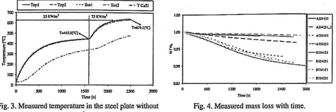
The temperature evolution in a steel plate without protection was also tested to attain the efficiency of this fire protection. The measured temperatures are presented in the Fig. 3 for a radiant heat flux of 35 [KW/m2] and then resetting the cone to 75 [KW/m2].
Fig. 4 represents the mass loss of each sample and shows a variation almost linear with time mainly for a heat flux of35 [kWm"2].
•mr---,r--~-,-~~1
- AlJ.l:)IJ
{=~~~~~~
.,.,
• • 11W lJ I
~~--~--- ~ --~
0 ICDI
""
a:m um'""
11.""1•1 Thoc (tl
Fig. 3. Measured temperature in the steel plate without Fig. 4. Measured mass loss with time.
protection.
Higher intumescence may be noticed in sample right region coincident to the thermocouples wire position responsible for coating accumulation. The presented values are mean values determined from four central measures.
-o-AJS·USl
I ....
A7,s.ll})~~==========================~
· 0 IlD! 1500
n ... l•l
Fig. 5. Intumescence thickness mean values of four central measurements.
The figures shown that for the lower heat flux the intumescence becomes stable, but for the higher it continues to increase. Coating A presents a higher expansion at the initial stage compared to the coating B. For longer exposure periods of exposure coating B continues to expand.
The steel temperature profiles and temperatures at the middle of the silicate plates are reported in Fig. 6 and Fig. 7. Measured values from the thermocouples welded on the bottom of the plate are very close to the temperatures at the top. For the same heat flux, the time to reach a same temperature increases with the increase of the dry thickness.
The behaviour is very similar for both coatings, but for all cases the time to reach, for example a temperature of 200 [0
c] is always higher when the paint B is used. For these conditions it gives an improved fire protection.
142
'""' I
I!
J:»l / __
.-·--··-··-lat i( _ .. ~··
.·'
..
'""
-··
'""
,.,,
---
...
=
""
-··
.
..,
·TC.SOl•n.+o-1!
-··-_
..
-
I
' : b = l
- ~ ·
--- ...
k , - - -,;;;;1'
I .
., ... -··-··-··-··-··-··-··-··-.. -·--··-·
I • • '
""
,.,
"n- t•l'""
=""'
""'
,.,,
---
...
-·-
TC.:OI
1·-·11
"'
t... -..
f.., ... -- .. ,
- · T~I
..
I=
...
1?---··-··---··-··-···
..,. .· ". .
..
-E
j=
..
(
~
__..
-··
-· ·- ·
·-··-··-··-··-·
.,··-· ~---~
•
- lD tsa""'
-. l\Mbl
I _,.,,
--':-..J . . . 1 - · a.: - T[»lI
..
E
i=
r.
.. --·-··-··-··-··-··
... ,.,
...
,....
-· ~---~ 0
..
..
(!
j=
., ,..-·
··
-··
=> ...TC.SO I
...
- ··
- ··-
··-··-··-Fig. 7. Temperature variation of steel nnd silicnlc plntes for conting B.
2 MATHEMATICAL MODEL OF THE INTUMESCENCE BEHAVIOUR
The problem to detennine the temperature field in an intumescent material involves the solution of a phase transformation problem with two ore more moving boundaries that characterize its state, initial, softened and carbonaceous char. Different methodologies can be found in the literature to model the thermal decomposition of a polymer or polymer based materials. The methodology followed in this work was to consider that the decomposition occurs not only at the outside surface but also inside, for temperatures above the pyrolysis temperature, TP . In this case the moving boundary regression rate must be detennined considering the motion of all domain. This strategy implies that a mass diffusion term needs to appear in the energy equation due its motion. This term was disregarded due to the small thickness of the virgin layer for this types of applications, about
1-3 [mm].
Considering a first order reaction, the mass loss is given by
a
____Ia_m(T(x,t))= :,• =-p.Aoe RTI•.t) for T?:.TP (1)
where rir is the local mass loss [kg. m"3s-1] , T (x,t) is the temperature at point x at instant t, ~is the pre exponential factor [s-1],
Eo
the activation energy [J.mor1], and R the universal gas constant [J.mor1 .K-1] . The position of the moving boundary is obtained by summing all the mass loss and dividing by the specific mass.The energy equation for the steel and virgin layers is based on the one-dimensional conduction heat equation.
The conservation equation for the solid virgin material phase is given by
ap.v. =-w-dv
ar
V •(2)
Where lV ~d represents the destruction rate of virgin material per unit volume, originated by the thermal decomposition. The virgin material decomposition produces a fraction of gas, equal to the porosity, 9', and a solid char fraction equal to
(I-
9').
The formation rate of char and gas mass is:
w:.
-
+-
;)p,A
d~~)
,;:;_,
-++-;:}}A~~)
(3).z
represents the fraction of the bulk density difference between the virgin and char materials that is converted to gas. In this study the value used was.z
= 0.66, [9] .(4)
In
the previous equationav jar
represents the intumescence rate. The gas mass flux, ril; , is calculated accordingly to Darcy's law and it is assumed that the gases present in the intumescent material behave as a perfect gas. The thermodynamic properties are related by the ideal gas law and, assuming that the gas is a mixture of 50wt%C02 and 50wt%Hp,
the generated gas molar mass used in the modelM
8 is31[g/mol].
The conservation of gas mass equation with the Darcy's and the ideal gas laws combined can be used to give a differential equation for the pressure inside the intumescence. In the numeric calculations, the intumescence rate is assumed to be Imown, provided by the experimental results, so the pressure calculation is disregarded being assumed that the internal pressure is constant and equal to the atmospheric pressure. An energy equation for the conservation of energy within the intumescence zone can be obtained by combining the energy equation for the gases with that of the solid char material. The equation for the conservation of energy per unit bulk volume can be written as:
(5)
The effective thermal conductivity for the intumescence bulk material, including gas and char, is equal to the thermal conductivity of the gas per unit bulk volume, plus that of the solid material. The same thing applies to the effective heat capacity.
In
the steel plate back surface it is assumed an adiabatic boundary condition and at the boundary steeUvirgin layers it is assumed a perfect thermal contact. At the moving front, the boundary conditions are:k aT =Ph· -eO"(T
4-T
4)-lz (T-T)
"
ax
-tr a c aaT
aT
k" ax
-k,ax
=Q11 forT(s(t),t)=Tp
for
T(s(t),t)<Tp
(6)
In which Q11 is the heat flux due to the endotherrnic decomposition of the virgin material, given by
Q
11 =-lzPp.s(t),
wherehP
represents the decomposition enthalpy. A wide range of values are reported in the literature for the heat of pyrolysis and go from a few units to units of millions. The value used in the calculations was 50 [J/kg].The intumescent coating specific mass was measured by the pycnometer method given a value of 1360 and 1250 [kg/m3] for the virgin coating and a value of 692.4 and 450 [kglm3] for the char material, for paints A and B, respectively. Steel properties are assumed constant, with a specific heat value of 600 [J/kgK] and a specific mass equal to 7850 [kg/m3] . The intumescent coating specific heat was considered constant and equal to 1000 [J/kgK].
The mathematical model is based on the following major simplifying assumptions: there is no heat between gas and char, the thermophysical properties and the pressure at both layers are constant. The solution method was implemented in a Matlab routine using the Method Of Lines (MOL), [ 1 0], and the integrator odel5s to solve the set of ordinary "differential equations.
The temperature field is determined by the steel and virgin energy equations. When the front reaches the pyrolysis temperature, equal to 250 [0c], starts to decompose and to move. Then the
moving front rate is determined and the intumescence forms. The position the free boundary is set equal to the experimental results and the intumescence temperature field is determined.
In
each time step the virgin and char layers are remeshed.The input parameters are listed as follows: k, =0.5Wm-•K-1; k< = o.nvm-•K-1 ; Cp. =2600Jkg-1K-1;
Two ca.Se studies are presented in Fig. 8 and Fig. 9. In the first one the steel temperature variation and the moving front position are determined based on a value of the activation energy equal to
E0 = 125KJmol-1• The numerical results follow reasonably well the experimental values. The major differences occur at intermediate times probably because a transition state of molten polymer was not considered.
CD
1 ~... - - tfti,J · u a.c.• -·a...a - ,..., ... 1
..
-··
""' = ""' ""',---==::-~"
,
... ~...
,
IJ! 11
"'
j
..
-Fig. 8. Compnrison of measured nnd computed steel temperatures and position of the moving front, E0 = 125KJmor1
"""
""'
EJ:
1-·ID-I:uru._.l • • m.t:ts • l~ l ·ID-IU•lD"Itu<-ll)
sa um t»:~ :m :Jm xm
"'-hi
1-uu-Cllm.I:S • • e hi [D.olb•U•~- • c u~ I:J-~1
~ »
-
1-r_----.·.---·-·-! ... .... ,
-..
-,
~ ltfll ~·· ;-"'
~""' I :
1 .••
1n
J
..
V'
\ \
.
)2) um ID :2m
n•hl
Fig. 9. Influence of the nctivation energy in the steel temperature nnd in the moving front.
Both the determined steel temperatures and the moving front are strongly dependent on the activation energy that defines the amount of mass loss of virgin paint, as presented in Fig. 9. It must be said that the value used in the simulations was obtained from the literature, but the correct value of both paints are needed. The reaction kinetics parameters can be obtained from thermogravimetric analysis.
ACKNOWLEDGMENTS
The nuthors ncknowledge the finnncinl support from the Portuguese Science and technology Foundation, project PTDC/EME-PME/64913/2006, " Assessment of Intumescent Paint Behaviour for Passive Protection of Structural Elements Submitted to Fire Conditions", nnd fellowship SFRH/BD/28909/2006. The authors acknowledge also the contribution from the paints producers: CIN, Nullifire.
REFERENCES
[1]. Duquesne, S.; Bourbigot, S. Delobel, R., "Mechanism of fire protection in intumescent coatings", European Coatings Conference: Fire Retnnlnnt Contings U, Berlin, 2007.
(2]. Stnggs J. E. J ., "A discussion of modelling idealised ablative materials with particular reference to fire testing", Fire Snfety Journal, Vol. 28, ,47-66, 1997.
[3]. Moghtndcri B., Novozhilov V., Fletcher, D., Kent J. H., "An integral model for the trnnsient pyrolysis of solid rnnterials" Fire nnd Materials, Vol. 21,7-16, 1997.
[4]. Lyon R. E., "Pyrolysis kinetics of char forming polymers", Polymer Degradation and Stability, N" 61, pp. 201-210, 1998.
[5]. Jia F., Gnlea E. R., Pate! M. K., "Numericnl Simulation of the Moss Loss Process in Pyrolizing Char Materials", Fire And Materials, N" 23,71-78, 1999.
[6]. Kuznetsov, G. V., Rudzinskii, V. P., "Heat trnnsfer in intumescent heat- and fire-insulating coatings", Journal of Applied Mechnnics and Technical Physics, Vol. 40, No. 3, 1999.
[7]. Mesquitn, L.M.R.; Piloto, P.A.G.: Vn:z., M.A.P.; Pinto, T.: "Numcricnl Estimation For Intumescent Thermal Protection Using One-Dimensional IHCP", WCCM8-ECCOMAS200B, ISBN: 978-84-96736-55-9, Venice, Itnly, June 30- July 5, 2008.
(8]. ISO 5660-1:2002, Reaction-to-fire tests- Heat release, smoke production and mass loss rate. Part 1: Heat release rnte {cone colorimeter method), Intemntionnl Organization for Standardization, 2002.
[9]. C. Lnutenbcrgcr, A Genernlized Pyrolysis Model for Combustible Solids, Ph.D . thesis, University of California at Berkelcy, Berkeley, CA, 2007.