parts with 3D laser scanner
Antonio Piratelli-Filho1,*, Alberto José Alvares1, and Rosenda Valdés Arencibia2
1 Universidade de Brasilia, Brasilia, Brazil 2
Universidade Federal de Uberlândia, Uberlândia, MG, Brazil Received: 1 August 2018 / Accepted: 24 September 2018
Abstract. This work presents a systematization method for digitization of mechanical parts with three-dimensional (3D) laser scanner using the process mapping method. The application involves the use of the IDEFØ methodology of process mapping to address the sequence of steps required to obtain the computer-aided design (CAD) model of the measured part. The variables involved in the setup and measurement with 3D laser scanner were investigated and applied to regular and free-form parts, and the parameter geometry, texture, light reflection and procedure of data acquisition were considered in the analysis. The software commands used to create the CAD models were also included and the ones related to mesh and surface creation were detailed. The systematized measurement planning was graphi graphically presented, and it proved useful to operators during the digitization process.
Keywords: process mapping / IDEFØ methodology / measurement planning / CAD modeling
1 Introduction
Process mapping has been considered as an important tool to acquire knowledge about the systems in any enterprise. This strategy is implemented by graphically presenting the full system operation at a very detailed level of complexity, thus consolidating a basis for decision making. Problems related to structure, control, staff or processes can be diagnosed and improved [1].
Its application begins by identifying the process activities, followed by ordering the sequence of steps and the resources required as labor, capital and materials [2]. The available techniques provide a representation of the system in different levels: (i) abstract: the product functions, the organization mission or some software tasks; (ii) organizational: organization structure and resources available; (iii) operational: detailed description of the product manufacturing or measurement/modeling [3]. Two types of models can be prepared: the descriptive to present how the process is, and the prescriptive to show how the process can be improved. These models can be built using modeling languages.
The most common modeling techniques are known as flowcharts, SIPOC Suppliers-Inputs-Process-Outputs-Customers, IDEF Integrated Definition Methods,
IDEFØ Integrated Definition Language 0, IDEF3– Integrated Definition Language 3 and IDEF-SIM [4].
The flowchart method corresponds to a graphical representation with a logical sequence describing a given work, process or general structure. It is composed of boxes having a summarized text explaining its function and lines and arrows showing the activities sequence. A rectangle is a commonfigure used, but other may apply, as well as colors and shadows. This tool allows the identification of a global model, but it has the disadvantage of resulting in a large graphic.
The SIPOC method allows the identification of the project limits as suppliers and customers, the main inputs and outputs of the process. These elements are represented by a diagram with interconnected boxes. This method is useful when most of the contribution variables are unknown. The IDEF method was developed by the Program for Integrated Computer-Aided Manufacturing (ICAM) of the U.S. Air Force to increase the manufacturing productivity by using computer technology. A group of techniques from IDEFØ to IDEF14 were developed to capture different kinds of information, according to the website of the Knowledge Basic System Inc. [5]. The most useful versions are the IDEFØ and IDEF3 methods.
The IDEFØ method requires the construction of flowcharts that interconnect the actions of the studied process carried out with the help of computer software [6,7]. This tool can be applied to model several automated and nonautomated systems or to analyze different functions in * Corresponding author:[email protected]
This is an Open Access article distributed under the terms of the Creative Commons Attribution License (http://creativecommons.org/licenses/by/4.0), which permits unrestricted use, distribution, and reproduction in any medium, provided the original work is properly cited.
complex implemented systems. Software are available to allow the assembly of a whole scheme, showing all the steps and decisions to be taken to improve a given manufacturing or measuring process. One of these software is the AI0WIN, which allows laying out the whole process in a diagram.
Reference [8] presented a review with examples of application of IDEFØ method in new product develop-ment, in industrial process mapping, in hospital services, in mapping enterprise activities inserted in ISO 9001 and in chemical process development. According to the author, the main elements used in IDEFØ technique are called UOB (unit of behavior), links, junctions and relatives. The UOB represents a process or activities and it is descripted by a rectangle (box). The links are represented by arrows, the junctions give the logic of ramification and the relatives are boxes with additional information.
The IDEF3 method is used to describe a network of events enabling the communication among members of the project. Modeling with IDEF3 may be carried out focusing on process or object and this application describes the events in real order of occurrence. The strategy focused on process is the most used to describe IDEF3 models.
The IDEF-SIM method was developed to carry out conceptual modeling of a system or process by using particular symbols. This method is used to simulate discrete events with the aim of helping the conversion of real to computational aspects [9]. The method was developed to be used in computers [4].
Examples of these modeling technique applications can be found in literature. Reference [9] presented a case study involving the application of IDEF-SIM method to process mapping of a hospital unity. Reference [10] compared IDEF-SIM method with SIPOC andflowcharts to address the problem of urban solid waste. Reference [11] presented some examples of using IDEFØ method to simplify the development of strategic plans. The authors found that the approach can be applied for strategy development or automation of small or large enterprises. Reference [12] compared the Structured Systems Analysis and Design Method (SSADM), IDEFØ and Agile Systems methodolo-gies applied to the development of systems with respect to the demand of the technology advances. The authors found that SSADM does notfit the new advances as well as Agile systems and IDEFØ. Reference [13] compared some tools applied in mapping the consumer activities in service commerce, among others the SIPOC and flowcharts. Reference [14] published a review on application of process mapping in surgery, presenting 17 case studies of a range of surgical specialties and they observed an improvement in surgical efficiency. Studies in chemical industry and product development process admitted the systematic and clear representation of complex activities [8].
By its characteristics, the IDEFØ method seems suitable to apply in processing of mechanical parts in modern industry where design and process are usually computerized and products are generally complex. In this area, the design and processing of products are done by computer-aided design (CAD) and computer-aided manufacturing (CAM), in search of time and cost reduction and production line flexibility. A known application of these CAD/CAM technologies is in reverse engineering,
where the part design begins by measuring a prototype or physical model to generate the CAD model in computer. The CAD model is used to develop a CAM manufacturing program which is implemented in a numerically controlled milling machine (CNC) or in a rapid prototyping machine (additive manufacturing) to produce the part.
It should be emphasized that this process begins and ends with the measurement of the part or physical model, in data acquisition and quality control steps. The measurement can be done in different ways, but the growing complexity of the parts has been demanding the use of instruments like coordinate measuring machines (CMM) and three-dimensional (3D) laser scanners. Three-dimensional laser scanner is a largely used ment to carry out contactless measurement. This instru-ment determines point coordinates by projecting a laser beam on the workpiece surface and employs the triangulation technique to calculate the coordinates in 3D space. Its application in reverse engineering allows obtaining one cloud of points representing the workpiece surface, which must befiltered and treated by a software for determining the surface geometry. By its character-istics, this instrument is often used to perform the measurement and reconstruction of CAD in reverse engineering process [15]. Digitization is a complex process with many variables involved that requires well prepared human resources. Nevertheless, hours are spent in scanning mechanical parts and there is a need of methodologies to systematize and simplify its application. The formalism of the measuring process planning technique can assist in the task of measurement, directing the inspector for the appropriate procedure. When verifying the conformity of part specifications in quality control, dimensioning is also required to compare with design tolerances [15]. There are no reports in literature referring to applications involving measurement tasks and process mapping techniques, in particular 3D laser scanner and IDEFØ method.
This work presents a process mapping application for digitization of mechanical parts using 3D laser scanner used to reconstruct CAD model of mechanical parts. In order to systematize the measuring process planning, the laser scanner software was carefully studied in respect to the available scanning options and interaction with the part surface finish. The measurement planning was done using AI0WIN software and applying the IDEFØ method. The identification of the variables involved in the measuring process and CAD model construction was performed through measuring tests with parts having regular and complex geometries.
2 Case study: application in a digitization
process
The IDEFØ method was developed to represent the activities, the decisions and the actions of a system [16].
With respect to main advantages of the IDEFØ, it should be mentioned that the method is considered effective for complex system activities modeling. The AI0WIN software is used to create activities model in
organization systems. Application to describe activities of any given measurement process requires good knowledge of the instrument operation to address the most important variables.
The 3D laser scanner used in this work requires the selection of a set of variables, depending on the part being measured, among several different possible settings to perform a given measurement. The operational settings are selected according to the type of piece, its geometry, the surface reflective properties, among others [17]. It is necessary to have good knowledge of the instrument operation for their correct use, as required to control the sources of errors and to reduce the measurement uncertainty.
The process mapping methodology was applied in a digitization process carried out with a 3D laser scanner manufactured by NextEngine, 2020i model. This laser scanner has four sources of laser beam with a wavelength of 0.650mm and 10 mW power each, with scan speed of 50,000 points/s. The coordinates of points are determined by the triangulation technique. Two modes of operation are available, Macro and Wide, having accuracy of 0.127 mm in Macro mode and 0.381 mm in Wide mode, according to the manufacturer.
Figure 1 shows the NextEngine laser scanner. This instrument has a unit for laser beam emission, with sensors to capture the reflected light beam. It presents a basis for positioning the workpiece, which directly connected to the main unit via USB connection. The basis has a rotation movement in relation to the horizontal (TILT) and vertical (TURN) axes and is connected to a rod with two brackets (supporter) to attach the part to be measured. The laser unit emits four laser beams projected over the part surface. These beams are reflected, captured and directed by internal lenses and picked up by internal sensors. A computational code is created for each reflected point on surface, determining the point coordinates on surface. A 3D mesh is formed by connecting the points by triangles. The size of these triangles depends on the scanner software settings.
The software ScanStudio was used to assist the scanner in the measurement process. A 3D mesh was generated from the cloud of points determined. This software allows some preliminary adjustments to the captured images besides enabling the initial setting of the instrument.
Another software, RapidWorks, was used to improve the initial model from ScanStudio. Data from ScanStudio were imported and displayed to make changes in order to correct small defects and leave the generated model closer to the real one. RapidWorks allows adjustments in the meshes of points, such as the filling of empty spaces or cutting unwanted parts. There is the possibility of creation of a new mesh and deploying it on the model previously measured or change an existing mesh.
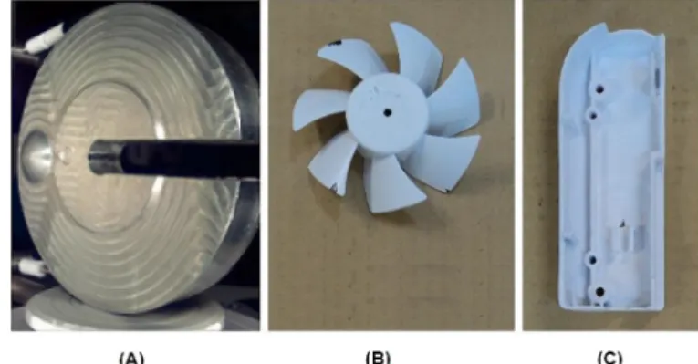
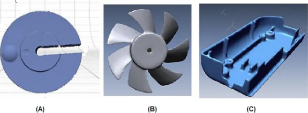
The measurement process was detailed for parts having different geometries and materials with regular and free-form surfaces, in wood, metal and plastic. The chosen parts had opaque and shiny surface, without any surface coating, to predict the need for application of chemicals for surface treatment. It must be noted that when performing the treatment of a piece with the deposition of some material on the surface, like an ink, this layer increases error in measurement. Figure 2 presents the parts selected, an aluminum-milled disk (a), a polycarbonate made runner (cooler) (b) and a polypropylene cover (c).
The planning of the measurement process was carried out to establish a systematization of the measurement steps with the 3D laser scanner. In this planning, a schema connecting all the main steps was prepared, showing the actions (functions) and decisions (mechanisms and con-trols) involved in measurement and relating them in accordance with the result of each and with the desired product. The AI0WIN software was used for development of the planning.
The AI0WIN software enabled the construction of a schema by connecting the most important variables in the measurement process. For each variable, the actions and decisions were observed and recorded to help the technician during the measurement process. In addition, the tools are used such as every action must be performed with some type of control. The actions are numbered and ordered with codes A*0, A*1, A*2, depending upon the number of important actions that are necessary and chosen for each process.
The experimental study began with the visual analysis of the selected pieces, followed by the positioning of the piece in the scanner base and the selection of ScanStudio software options to perform the measurement. An alignment should be made, followed by the junction of the images obtained by the scanner, smoothing and Fig. 1. Three-dimensional laser scanner.
Fig. 2. Measured parts: (a) aluminum-milled disk; (b) polymeric runner; (c) polymeric cover.
repairing of voids and defects of the mesh generated. The mesh should be exported to the RapidWorks, where the remaining voids must befilled and the remaining defects repaired. To finish the process, a surface should be generated from the mesh, in which the distances and angles shall be quantified.
3 Results and discussion
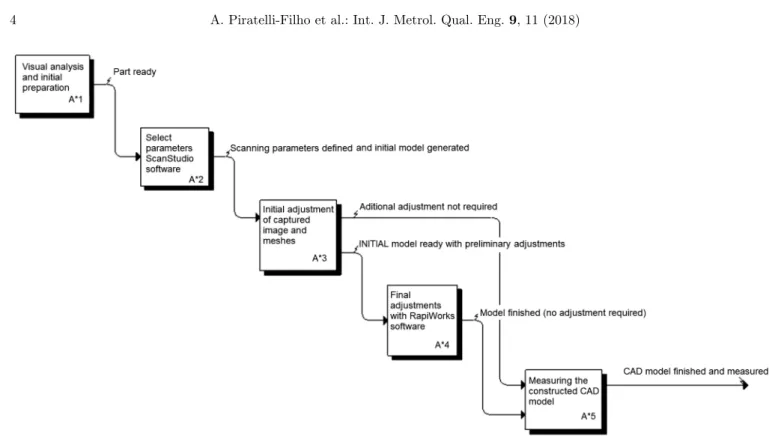
Having the scanner hardware and software been studied, theflowchart of the measurement process was determined with five main levels or actions, named A*1 to A*5 and shown in Figure 3. The decisions into the actions were numbered according to the measured part and the related main action, for instance, the A*11 is related to thefirst decision in the main action A*1.
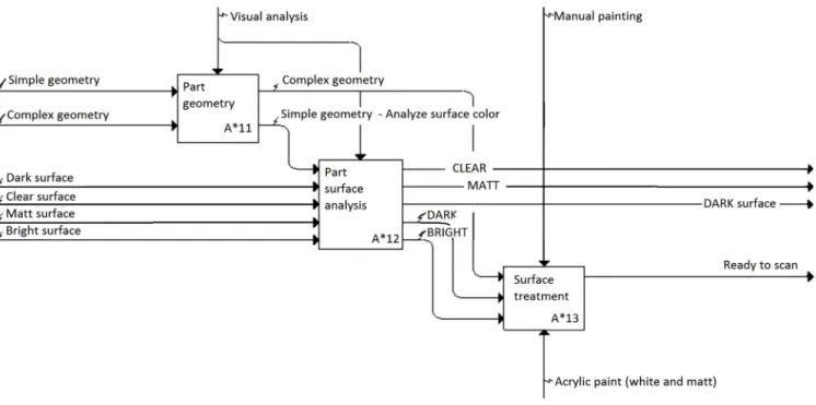
Thefirst action to be performed (A*1) consists of visual analysis of the mechanical part and positioning in the scanner basis. In this action, some decision making was required, as shown inFigure 4. Thefirst decision is related to the initial visual analysis to check the part geometry. If the piece has free form and presents complex geometric elements, it must be subjected to a surface treatment. If the geometry is simple, the analysis of the surface color of the specimen is sufficient. Note that parts with a clear or matt surface color do not require surface treatment, whereas those of dark or bright coloration need such treatment. The last step to be taken in this action is the implementation of surface treatment, with the application of white acrylic paint and matte color for easy scanning. Among the parts used in the study, the aluminum-milled disk presents a simple geometry and glossy metal surface and then it must be coated with dye-penetrant ink, while the polymeric runner and cover were coated with matt white acrylic paint.
The second action to be performed is the configuration of the ScanStudio software for image formation and mesh generation.Figures 5and6show the main decision making within this action. Initially, one should make the analysis of the color of the specimen to adjust the target tool. Then, setting the number of divisions to determine the number of images generated for the formation of the mesh should be done depending on the geometry. For parts with complex and very detailed geometry, a setting with more than 10 divisions is required. For simple and less detailed parts, less than 10 divisions are required. The adjustment of more than one family of settings makes easier the process of collecting points, and parts with complex geometry need at least three families of configurations, while simple parts require less than three families (Fig. 5).
When a volumetric 3D model is required, it is necessary to fit the “scanner vision” to 360 for the first family. Parts with complex and very detailed geometry need more pictures and usually only a single view of the piece (single). When only one fraction of the part is desired, the bracket option may be used, taking three views of the part. The basis where the part is positioned can be tilted or rotated around its own axis and this action may be defined in ScanStudio. Parts with complex geometry need inclined views to provide further details, unlike parts with simple geometry. The surface texture may be determined by increasing the resolution of image capture. Parts with complex geometry and detailed texture require usually SD3, HD1 or HD2 fittings, while simple parts require settings SD1 or SD2. Finally, the scanner must be activated to data point acquisition, which can occur in one or more orientation, vertical and/or horizontal, depending on the completeness of the generated model (Fig. 6).
Table 1presents the values of the scanner variables in the digitization of the three parts investigated. In this table, it must be pointed out that the number of divisions is the number of images taken to create a mesh. The target is related to the surface lighting and is related to color evaluation (options light or neutral). The family presents the configuration in each digitization and the position provides the number of views of the part (360 is equivalent to full volume, bracket is associated with three views and
single to a unique view). The tilt and start correspond to the inclination in respect to the horizontal direction, and the texture is equivalent to the image resolution (SD has lower resolution and HD has higher resolution). Finally, the digitization is equivalent to the part orientation during measurement.
It was observed that the polymeric runner demanded only two families, with measurements in the horizontal and vertical directions. This configuration was Fig. 4. Decisions associated with the A*1 action.
enough because the runner has a simple geometry, despite its free-form surface, but the texture demanded high definition HD1 for scanning. In the case of the polymeric cover, there are several free-form surfaces that required the digitization of 10 families, using texture settings at SD3, HD1 and HD2. The aluminum-milled disk
presents some features with smooth surfaces and the digitization demandedfive families, with texture settings at SD2.
The third action corresponds to the initial settings of the created meshes, held by ScanStudio software, after collecting the points. Figures 7 and 8 show the Fig. 6. Decisions A*24 to A*27 of the A*2 action.
Table 1. Variablesfitted on scanner to carry out measurements.
Part Divisions Target Family Position Tilt Start Texture Digitization
Aluminum-milled disk
10 Light A 360° 5 0 SD2 Vertical
8 Light B Bracket 33 11 SD2 Vertical
6 Light C Bracket 93 7 SD2 Vertical
10 Light D Single 120 0 SD2 Vertical
10 Light E Single 76 13 SD2 Vertical
Polymeric runner 1010 LightLight AA 360360°° 00 00 HD1HD1 HorizontalVertical
Polymeric cover
8 Neutral A 360° 0 0 SD3 Vertical
8 Neutral A 360° 0 0 SD3 Horizontal
8 Light B Single 26 2 HD1 Horizontal
8 Light C Single 26 0 HD1 Horizontal
8 Light D Single 24 24 HD1 Horizontal
8 Light E Single 34 0 HD1 Horizontal
8 Light F Single 29 24 HD2 Horizontal
8 Light G Single 28 42 HD2 Horizontal
8 Light H Single 25 3 HD2 Horizontal
decision to be made within this action. Initially, it was necessary to cut unwanted points with the trim command. After this cleaning operation, the manual alignment of all images generated must be accomplished.
In the case of a big number of images, the manual alignment requires the insertion of pins of same color in the same locations on the images to be aligned. An adjustment should be made considering a tolerance value Fig. 7. Decisions A*31 to A*34 of the A*3 action.
of deviations between the images, and the 3D model more closely approximates the real model with reduction in tolerance value. The third decision to be taken is the junction of the generated images in a single image, using the fuse command, in order to obtain a single mesh points.
The mesh obtained can still present empty spaces, being necessary tofill in the voids with the help of software commands. Simple defects are corrected with the polish command in ScanStudio, together with the simplification of the mesh of points by discarding unnecessary points. When the parts are very large, the construction is performed with a second software, RapidWorks. When major meshes adjustments are not necessary, the measure-ment of the model parameters is performed. Anyway, later adjustments may be required and thus the output tool is used to export the CAD model to be finished in the RapidWorks software.
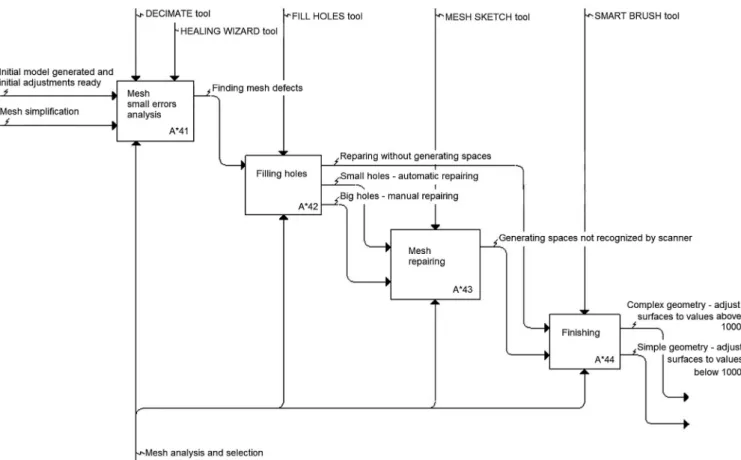
The fourth action corresponds to the final adjust-ments in the obtained mesh using the RapidWorks software. Figures 9 and 10 present the decisions to be taken in such an action. Thefirst decision is related to the mesh analysis in respect to the residual small errors, for instance, the intersection of edges or small empty spaces. Initially, the healing wizard tool may be applied to provide an error mapping. The decimate tool can be used to simplify the mesh, being recommended for application with more complex geometries. The remain-ing failures such as the large voids require manual
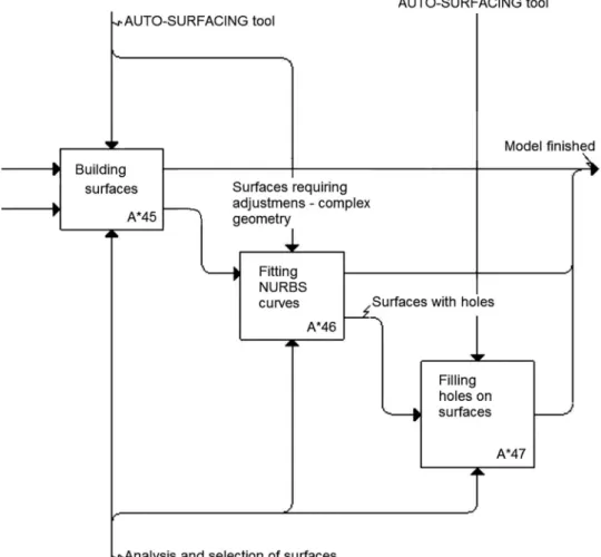
corrections that are carried out using the build tools. To provide a more uniform and close to real model, some finishing operations should be made, such as the smoothing of edges and smoothing of extreme points, among others. Once finished the mesh, the model surfaces must be generated through the adjustment of NURBS curves and surfaces. It may still be necessary to fill in areas that have not been correctly generated with NURBS modeling.
Figure 11 presents the final meshes generated for the aluminum-milled disk, the polymeric runner and the polymeric cover. Figure 12 presents the resulting CAD models after adjustment operations defined for planning the measurement with the laser scanner. These models are ready to be used as a reference for measuring the geometric parameters, such as heights, widths, diameters and thicknesses.
The fifth action (A*5) consists in the measurement of the model obtained using the RapidWorks software tools (Fig. 13). All decisions of this action depend on the demanded type of analysis, such as mesh points evaluation, determination of bends and deviations and calculation of diameters, distances, volume and surface area, among others.
Some length measurements were performed on parts under study. In the aluminum-milled disk, the internal diameter was determined as 15.161 mm, the external diameters were 55.827 and 115.426 mm, the thickness of the shoulder (region of smaller external diameter) was Fig. 9. Decisions A*41 to A*44 of the A*4 action.
2.013 mm and the overall thickness was 22.474 mm. The polymeric runner was measured and the outer diameter of the central part was 32.276 mm.
4 Conclusion
The study of measuring process planning with a NextEngine 3D laser scanner was made and the detailed planning of the measurement steps was prepared using the
AI0WIN software, with the application of the IDEFØ method. The tests with regular and complex geometry parts allowed the identification of variables involved in measurement and CAD model generation, creating a sequence of actions and decisions that facilitate the measurement with this device.
The IDEFØ method using the software AI0WIN was efficient to build the model of the measurement with the 3D laser scanner. The sequence of steps was clearly identified by applications measuring three different parts, resulting Fig. 10. Decisions A*45 to A*47 of the A*4 action.
in a general model for measurements with laser scanner. Performed tests resulted in time reduction by both skilled and nonskilled operators.
In the case study, among the variables that influence the measurement with laser scanner, it was observed that the part color, the surface finish, the material and the geometry are the most important. It was observed that parts with regular geometries, with matte and clear coloring, do not require surface treatment before scanning. On the other hand, parts with free-form geometries and many details (complex), dark colors and shiny surfaces require a surface treatment before measurement. It was further observed that as the part complexity increases, it was necessary to take more pictures for modeling to avoid
empty spaces and deformations and to reduce the repairing work. Theflowcharts developed enabled the measurement of geometric parameters of the parts.
Future studies may be carried out to apply the method in another complex measuring system and to evaluate the measurement uncertainty. Other methods can be applied to execute computational simulations, as IDEF-SIM method.
5 Implications and in
fluences
The present approach of using process mapping techniques to systematize the measurement process of a 3D laser scanner helps in operation of the instrument, especially Fig. 12. CAD models of the aluminum-milled disk, polymeric runner and polymeric cover.
Process Management (Paton Press, Chico, CA, 2005) 2. M. Laguna, J. Marklund, Business Process Modelling,
Simulation, and Design (Pearson Education, Upper Saddle River, NJ, 2005)
3. O.A. Glassey, Case study on process modelling: three questions and three techniques, Decis. Support Syst. 44, 842–853 (2008)
4. J.A.B. Montevechi, F. Leal, A.F. Pinho, R.F.S. Costa, M.L. M. Oliveira, A.L.F. Silva, Conceptual modeling in simulation projects by mean adapted IDEF: an application in a Brazilian Tech Company, in Proceedings of the 2010 Winter Simula-tion Conference (IEEE, Baltimore, MD, 2010)
5. KBSI®IDEFØ methods & standards. Available at http:// www.kbsi.com/solutions-and-services/idef-methods-and-standards (accessed February 16, 2018)
6. V. Serifi, P. Dasic, R. Jecmenica, D. Labovic, Functional and information modeling of production using IDEF methods, J. Mech. Eng. 55, 131–140 (2009)
7. Z. Nicolic, M. Nicolic, S. Jerinic, A solution in the development of the billing and information system, Int. J. Econ. Law 10, 43–49 (2014)
8. M.L.M. Oliveira, Análise da aplicabilidade da técnica de modelagem IDEF-SIM nas etapas de um projeto de
strategy using IDEFØ: a proof of concept, Operations Res. Perspect. 2, 106–113 (2015)
12. F.A. Abdulla, N. Zhang, What the current system develop-ment trends tell us about systems developdevelop-ment methodolo-gies: toward explaining SSDAM, Agile and IDEFØ methodologies, J. Appl. Comput. Sci. Math. 9, 9–15 (2015) 13. G.A. Jorge, D.I. Miyake, Estudo comparativo das ferramen-tas para mapeamento das atividades executadas pelos consumidores em processos de serviço, Production 26, 590–613 (2016)
14. R.D. Chung, D.J. Hunter-Smith, R.T. Spychal, V.V. Ramakrishnam, W.M. Rozen, A systematic review of intraoperative process mapping in surgery, Gland Surg. 6, 715–725 (2017)
15. P. Tang, B. Akinci, Formalization of workflows for extracting bridge surveying goals from laser-scanned data, Autom. Constr. 22, 306–319 (2012)
16. IDEF, Integrated definition methods. Available at http:// www.idef.com/idefo-function_modeling_method/
(accessed February 16, 2018)
17. NextEngine. NextEngine scanner specs. Available at
http://www.nextengine.com/assets/pdf/scanner-tech specs.pdf(accessed February 16, 2018)
Cite this article as: Antonio Piratelli-Filho, Alberto José Alvares, Rosenda Valdés Arencibia, Application of process mapping for digitization of mechanical parts with 3D laser scanner, Int. J. Metrol. Qual. Eng. 9, 11 (2018)