Defects tracking in Out-of-Autoclave
composite materials
Mariana da Gama e Castro Moura Soares
Supervisor:Prof. Dr. Ant´onio Torres Marques
A Thesis submitted to the Faculty of Engineering, University of Porto in partial fulfillment of the requirements for the degree of
Master of Science in Mechanical Engineering
“I may not have gone where I intended to go, but I think I have ended up where I needed to be.”
Abstract
Keywords: Composites, Curing Process, Out-of-Autoclave, Finite Element Analy-sis (FEA).
Advanced thermosetting carbon fibre reinforced polymers (CFRP) have become common in primary aerospace structures, along with high performance sporting goods and marine and wind energy structures. As these composite parts grow in number, size and complexity, the need for faster, more cost effective and more versa-tile manufacturing comes into conflict with the limitations of traditional processing methods.
The cure of the resin is a process phase of utmost importance in vacuum bag only (VBO) and resin transfer moulding (RTM) processes, as it is for composite manufacturing processes in general. The result of the curing process determines the quality of a part due to its great influence on mechanical and chemical properties and life cycle of the part under high temperature. Therefore, the discussion of the curing process is of tremendous importance and value.
In the cure of a thermoset fibre-reinforced composite laminate, stress and strain develop as the matrix resin undergoes crosslinking reactions accompanied by chemi-cally induced volumetric shrinkage. In addition to this cure-induced effect, thermal deformation occurs during the subsequent cooling. Consequent residual stress and strain can cause shape distortion and premature failure of the cured composite. Therefore, cure process optimization is important and costly trial-and-error meth-ods are often necessary to set appropriate tool geometry and cure cycle.
In the present work, a computational analysis of the curing process of a specific part is performed in two different softwares. Three distinct materials, (AS4/8552, IM7/5250-1 and a non-crimped fabric composed by HTS fibres and RTM6 epoxy ma-trix) each corresponding to a different manufacturing process, are analysed. Firstly, using Raven® and with an adequate application of boundary conditions, it is pos-sible to obtain the value of the heat transfer coefficient that cures the composite laminate part and generates a laminate and mould temperature distribution that follow the curing temperature. Secondly, a finite element model is generated and, using the results from Raven®, it is possible to obtain the strain gradient of the part in study and consequently, possible locations for defects to occur in the composite laminated part.
Resumo
Palavras-chave: Comp´ositos, Processo de cura, Fora-de-autoclave, An´alise de Elementos Finitos (AEF).
Os Pol´ımeros Refor¸cados com Fibra de Carbono (PRFC) tornaram-se uma mat´ eria--prima comum na ind´ustria aeroespacial, assim como no fabrico de bens desportivos de alta performance e de estruturas para obten¸c˜ao de energia, tanto marinhas como e´olicas. Com o crescimento da utiliza¸c˜ao de pe¸cas fabricadas em materiais comp´ osi-tos surgiu a necessidade de produzir pe¸cas maiores e mais complexas e, consequente-mente, a necessidade de um fabrico mais r´apido, rent´avel e vers´atil, o que deixou de ser poss´ıvel obter atrav´es de processos de fabrico tradicionais.
Uma fase de extrema importˆancia tanto no processo VBO como no RTM ´e a fase da cura da resina. O resultado do processo de cura da resina determina a qualidade da pe¸ca fabricada, influencia as propriedades mecˆanicas, o ciclo de vida da pe¸ca a elevadas temperaturas e as propriedades qu´ımicas, sendo de extrema importˆancia a discuss˜ao e estudo do processo de cura no fabrico de uma pe¸ca em material comp´ o-sito.
Na cura de um comp´osito laminado de resina termoendurec´ıvel refor¸cada com fibra, as tens˜oes e deforma¸c˜oes desenvolvem-se de acordo com as rea¸c˜oes de liga¸c˜ao cruzadas sofridas pela matriz de resina e com o encolhimento volum´etrico induzido quimicamente. Para al´em deste efeito da cura, ocorre deforma¸c˜ao t´ermica na fase de arrefecimento subsequente, o que provoca o aparecimento de tens˜oes e deforma¸c˜oes residuais que podem causar deforma¸c˜oes na geometria da pe¸ca e uma rutura pre-matura na pe¸ca curada. Desta forma, a otimiza¸c˜ao do processo de cura torna-se de importˆancia imperativa, sendo muitas vezes necess´arios m´etodos de tentativa e erro caros, de forma a determinar a geometria do molde e o ciclo de cura mais apropriados.
No presente trabalho, ´e feita uma an´alise computacional do processo de cura uti-lizando dois softwares distintos. S˜ao analisados trˆes materiais diferentes (AS4/8552, IM7/5250-1 e um tecido non-crimped composto por fibras HTS e uma matriz de resina RTM6), cada um correspondente a um diferente processo de fabrico. A simu-la¸c˜ao ´e iniciada utilizando o software Raven® e aplicando as condi¸c˜oes de fronteira adequadas, sendo poss´ıvel obter o valor do coeficiente de transferˆencia de calor que cura o laminado e que gera a distribui¸c˜ao de temperatura, deste e do molde, que acompanha a temperatura de cura. Seguidamente, ´e gerado um modelo de elementos finitos e, utilizando os resultados obtidos no Raven®, ´e poss´ıvel obter a distribui¸c˜ao
de tens˜oes na pe¸ca e, consequentemente, as poss´ıveis localiza¸c˜oes para aparecimento de defeitos.
Acknowledgements
I would like to take this opportunity to express my gratitude to my supervisor, Prof. Dr. Ant´onio Torres Marques, for his availability throughout the time of this work and his effort to make this a theme I would be interested to work on.
I am grateful to Professor Pascal Hubert for taking the time to guide me on the formulation of the approach of the problem and for providing me with a Raven® software licence.
To the friends I made during these years at the university, for the joyful and for the though times spent together. To Ana, Ana, Catarina, Joana, Joana, Pedro e Rafa. To my long time friend Inˆes for always caring.
To Lu´ıs for his support and affection and for his readiness to help, always willing to share his knowledge.
To all my family, in particular to my brother and sister and to my grandparents. And mostly to my parents, without whom this would not be possible, for their un-conditional support thoughtout this journey.
Contents
Abstract i Resumo iii Acknowledgements v List of symbols ix List of figures xiList of tables xiv
1 Introduction 1 1.1 Background . . . 1 1.2 Rational . . . 3 1.3 Problem Statement . . . 3 1.4 Objectives . . . 3 1.5 Thesis layout . . . 4 2 State-of-the-art 5 2.1 Composite materials . . . 5
2.2 Manufacturing composite processes . . . 6
2.2.1 Autoclave processing . . . 7
2.2.2 Open moulding processes . . . 9
2.2.3 Closed moulding processes . . . 12
2.3 Curing process . . . 29
2.4 Manufacturing defects . . . 30
2.5 RAVEN® simulation software . . . 33
3 Numerical Simulations 37 3.1 Geometry . . . 38 3.2 Materials . . . 39 3.3 Step I - RAVEN® . . . 42 3.3.1 Autoclave . . . 42 3.3.2 VBO . . . 45
3.3.3 Results and discussion . . . 48
3.4 Step II - Finite element modelling . . . 49
3.4.1 Autoclave . . . 50
viii Contents
3.4.3 VBO . . . 60 3.5 Discussion . . . 66
4 Conclusions and Future Work 67
4.1 Conclusions . . . 67 4.2 Future work . . . 68
Bibliography 69
List of Symbols
Chapter 2
φ In-plane fibre angle of the FW process;
θ In-plane fibre angle of the FW process;
w Total tow width of the FW winding process;
ω Rotational speed of the mandrel of the FW process;
F Total force that the tows create in the head of the FW process; V Axial velocity of the moving platform of the FW process;
Ca* Modified capillary number;
µ Resin dynamic viscosity;
¯
u Global resin velocity;
γ Surface tension of resin;
θ Contact angle between the resin and fibres;
u Axial displacement in the x direction;
Chapter 3
E11c Longitudinal laminate level Young’s modulus; E22c Transversal laminate level Young’s modulus;
E33c Through-thickness laminate level Young’s modulus; ν12c In-plane laminate level Poisson’s coefficient;
ν13c Longitudinal laminate level Poisson’s coefficient; ν23c Through-thickness laminate level Poisson’s coefficient; Gc12 In-plane laminate level shear modulus;
Gc13 Longitudinal laminate level shear modulus; Gc23 Through-thickness laminate level shear modulus;
ρc Laminate level density;
cc Laminate level specific heat;
kc11 Longitudinal laminate level heat conductivity coefficient; kc22 Transversal laminate level heat conductivity coefficient; kc33 Through-thickness laminate level heat conductivity coefficient; αc11 Longitudinal laminate level coefficient of thermal expansion; αc22 Transversal laminate level coefficient of thermal expansion;
ωf Fibre volume fraction;
E11f Fibres longitudinal fibres Young’s modulus; E22f Fibres transversal fibres Young’s modulus; ν12f Fibres in-plane fibres Poisson’s coefficient;
x List of Symbols
Gf12 Fibres in-plane shear modulus;
ρf Fibres density;
kf11 Fibres longitudinal heat conductivity coefficient; kf22 Fibres transversal heat conductivity coefficient; αf11 Fibres longitudinal coefficient of thermal expansion; αf22 Fibres transversal coefficient of thermal expansion;
Em Matrix Young’s modulus;
νm Matrix Poisson’s coefficient;
Gm Matrix shear modulus;
ρm Matrix density;
km Matrix heat conductivity coefficient; αm Matrix coefficient of thermal expansion;
EI Invar 36 Young’s modulus;
νI Invar 36 Poisson’s coefficient;
GI Invar 36 shear modulus;
ρI Invar 36 density;
kI Invar 36 heat conductivity coefficient; αI Invar 36 coefficient of thermal expansion;
Es Stiffener Young’s modulus;
νs Stiffener Poisson’s coefficient;
Gs Stiffener shear modulus;
ρs Stiffener density;
ks Stiffener heat conductivity coefficient; αs Stiffener coefficient of thermal expansion;
List of Figures
2.1 Schematic view of vacuum bagging for autoclave processing [1]. . . . 7
2.2 Schematic view of the set up inside an autoclave and principal of autoclave curing [2]. . . 8
2.3 Schematic view of a typical autoclave device [2]. . . 8
2.4 Schematic view of the hand lay-up process [3]. . . 9
2.5 Schematic view of the spray lay-up process [3]. . . 10
2.6 Schematic view of the FW process [2]. . . 11
2.7 Filament winding patterns [2]. . . 11
2.8 Schematic view of the roll wrapping process [4]. . . 12
2.9 Schematic view of the Compression moulding [5]. . . 13
2.10 Injection moulding cyclic process [6]. . . 15
2.11 General steps of Reaction Injection Moulding (RIM) [7]. . . 16
2.12 General steps of the Vacuum Infusion (VI) process [8]. . . 17
2.13 Schematic view of the resin film infusion process [9]. . . 18
2.14 Schematic view of the Centrifugal Casting process [10]. . . 19
2.15 Schematic view of continuous lamination [10]. . . 19
2.16 Schematic view of the pultrusion process [11]. . . 20
2.17 Schematic view of injected pultrusion [11]. . . 21
2.18 Schematic view of QuickstepTM process [12]. . . 21
2.19 Schematic view of RTM [8]. . . 23
2.20 Schematic view of VARTM process [13]. . . 24
2.21 Schematic view of SCRIMP [14]. . . 25
2.22 Resin injection sequence in the HPIRTM process [15]. . . 26
2.23 Resin injection sequence in the HPCRTM process [15]. . . 26
2.24 Schematic and micrograph of air evacuation channels in VBO prepreg [16]. 27 2.25 Schematic of evacuation of entrapped air from VBO prepreg. [11]. . 28
2.26 VBO lay-up schematic [16]. . . 28
2.27 Void formation mechanism in the RTM process [17]. . . 31
2.28 Void content as a function of modified capillary number [17]. . . 31
2.29 Influence of various process parameters on porosity in VBO compos-ites [16]. . . 32
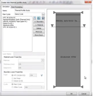
2.30 1st explanation figure of the RAVEN® software. . . 34
2.31 2nd explanation figure of the RAVEN® software. . . 35
2.32 3rd explanation figure of the RAVEN® software. . . 35
2.33 4th explanation figure of the RAVEN® software. . . 36
2.34 5th explanation figure of the RAVEN® software. . . 36
xii List of Figures
3.2 Laminate parts . . . 39
3.3 Laminate parts . . . 39
3.4 Variation of the CTE with fibre volume fraction for the reported con-stituents [18, 19, 20, 21]. . . 41
3.5 Autoclave model setup in Raven®. . . 43
3.6 Curing temperature distribution of the autoclave model. . . 43
3.7 Mould and laminate temperature vs curing temperature distribution for the autoclave process for different values of h. . . 44
3.8 Degree of cure of AS4/8552 during curing cycle for h = 80 W/m2K. 45 3.9 Cure rate of AS4/8552 during curing cycle, for h = 80 W/m2K. . . . 45
3.10 VBO model setup in Raven®. . . 46
3.11 Curing temperature distribution of the VBO model. . . 46
3.12 Mould and laminate temperature vs curing temperature distribution for the VBO process for different values of h. . . 47
3.13 Degree of cure of IM7/5320-1 during curing cycle for h = 50 W/m2K. 48 3.14 Cure rate of IM7/5320-1 during curing cycle for h = 50 W/m2K. . . 48
3.15 Autoclave and VBO computational models and evidence of the eight plies. . . 49
3.16 RTM computational model. . . 49
3.17 Pressure load distribution applied during curing process in the auto-clave model. . . 50
3.18 Loads and BC applied to the autoclave computational model. . . 51
3.19 Strain distribution in the first ply after the curing process. . . 51
3.20 Stress distribution in the first ply after the curing process. . . 51
3.21 Strain distribution in the second ply after the curing process. . . 52
3.22 Stress distribution in the second ply after the curing process. . . 52
3.23 Strain distribution in the third ply after the curing process. . . 52
3.24 Stress distribution in the third ply after the curing process. . . 52
3.25 Strain distribution in the fourth ply after the curing process. . . 53
3.26 Stress distribution in the fourth ply after the curing process. . . 53
3.27 Strain distribution in the fifth ply after the curing process. . . 53
3.28 Stress distribution in the fifth ply after the curing process. . . 53
3.29 Strain distribution in the sixth ply after the curing process. . . 54
3.30 Stress distribution in the sixth ply after the curing process. . . 54
3.31 Strain distribution in the seventh ply after the curing process. . . 54
3.32 Stress distribution in the seventh ply after the curing process. . . 54
3.33 Strain distribution in the eigth ply after the curing process. . . 55
3.34 Stress distribution in the eigth ply after the curing process. . . 55
3.35 RTM 6 cure cycle for composite manufacture [22]. . . 55
3.36 Loads and BC applied to the RTM computational model. . . 56
3.37 Strain distribution in the first ply after the curing process. . . 57
3.38 Stress distribution in the first ply after the curing process. . . 57
3.39 Strain distribution in the second ply after the curing process. . . 57
3.40 Stress distribution in the second ply after the curing process. . . 57
3.41 Strain distribution in the thrid ply after the curing process. . . 58
3.42 Stress distribution in the third ply after the curing process. . . 58
3.43 Strain distribution in the fourth ply after the curing process. . . 58
List of Figures xiii
3.45 Strain distribution in the fifth ply after the curing process. . . 59
3.46 Stress distribution in the fifth ply after the curing process. . . 59
3.47 Strain distribution in the sixth ply after the curing process. . . 59
3.48 Stress distribution in the sixth ply after the curing process. . . 59
3.49 Strain distribution in the seventh ply after the curing process. . . 60
3.50 Stress distribution in the seventh ply after the curing process. . . 60
3.51 Strain distribution in the eigth ply after the curing process. . . 60
3.52 Stress distribution in the eigth ply after the curing process. . . 60
3.53 Loads and BC applied to the VBO computational model. . . 61
3.54 Strain distribution in the first ply after the curing process. . . 62
3.55 Stress distribution in the first ply after the curing process. . . 62
3.56 Strain distribution in the second ply after the curing process. . . 62
3.57 Stress distribution in the second ply after the curing process. . . 62
3.58 Strain distribution in the third ply after the curing process. . . 63
3.59 Stress distribution in the third ply after the curing process. . . 63
3.60 Strain distribution in the fourth ply after the curing process. . . 63
3.61 Stress distribution in the fourth ply after the curing process. . . 63
3.62 Strain distribution in the fifth ply after the curing process. . . 64
3.63 Stress distribution in the fifth ply after the curing process. . . 64
3.64 Strain distribution in the sixth ply after the curing process. . . 64
3.65 Stress distribution in the sixth ply after the curing process. . . 64
3.66 Strain distribution in the seventh ply after the curing process. . . 65
3.67 Stress distribution in the seventh ply after the curing process. . . 65
3.68 Strain distribution in the eigth ply after the curing process. . . 65
List of Tables
3.1 Composite laminated skin material properties [23, 24, 25, 26] . . . . 40 3.2 Invar 36 material properties [27] . . . 42 3.3 Stiffener material properties . . . 42
Chapter 1
Introduction
1.1
Background
Advanced composite materials are becoming increasingly used in the critical struc-tures of both civilian and military aircraft, as they often have a higher strength-to-weight ratio compared to conventional materials, higher stiffness, are corrosion resistant and are able to be tailored to meet specific mechanical criteria.
The excellent mechanical properties of fibrous composites have enabled them to be applied to the design of various structures, in which their performance has been closely investigated. However, a variation in some factors, particularly, resid-ual stress, a crucial factor during the forming process, may ultimately affect the performance of the final product [28].
Cure simulation is an effective tool to predict the cure-induced stress/strain in a composite component and to determine an appropriate process in a reasonable manner with minimal trial-and-error. The accuracy of the simulation depends on the chemical curing process. There are two key factors for the accurate simulation. Input of appropriate material parameters is the first, as without accurate input pa-rameters the simulation cannot reproduce the actual internal state of the curing composite; secondly, the validation of the simulation, without which it is impossible to confirm the validity of the approach employed [29].
White and Hahn, were two of the first authors to develop a process model for an autoclave or hot pressing process. Their papers address the issue of un-derstanding how residual stresses develop during processing and how they can be predicted, by developing a process model which can be used to predict the residual stress history during the curing of composite laminates [30] with experimental vali-dation [31]. Costa and Sousa [32] developed a three-dimensional numerical model to simulate and to analyse the mechanisms dealing with resin flow, heat transfer and the cure of thick composite laminates during autoclave processing. It is based on the Darcy law, the convection-diffusion heat equation and appropriate constitutive relations. Ganapathi et al. [33] developed a simulation process that simultaneously accounts for all physical phenomena involved in a composite manufacturing process. It attempts to accomplish this by coupling heat transfer, cure kinetics, rheology, 1-D consolidation and 2-D resin flow within and out of curing laminates in a transient
2 Chapter 1. Introduction
manner. Abdelal et al. [34] developed an autoclave process model which includes the effect of the thermal and mechanical properties of the contact layer between the part and the tool on the residual stress by applying an FE-Explicit solver. Yoo et al. [28] presented a simulation of the curing of a carbon/epoxy laminate by taking into consideration the phase changes of the epoxy resin and the corresponding mate-rial property changes in the laminate. The simple technique for simulating the entire curing process with simple mechanical properties was developed using FEA, which predicted well the overall change in the generated strains in the composite laminate during the curing process. More recently, Sreekantamurthy et al. [35] developed cure process models of composite parts using commercial off-the-shelf software to analyse and understand the cure responses with reference to the known physics of the composite curing process, and to compare the residual strain predictions from the analysis with those measured using fibre optics strain sensors in the laboratory. RAVEN® and COMPRO® commercial softwares were used to conduct analytical studies on the cure process modelling of composite autoclave curing process.
Trochu et al. [36] benefited as well from the FEM to study in a computational environment the RTM process. They obtained with the computer simulation the resin pressure distribution and the resin front positions. The calculated results for selected mould geometries are compared with experimental observations. Liu et al. [37] presented three simulation features (gate control, venting, and dry spot for-mation) developed in an existing mould filling simulation code for RTM to address the processing issues encountered during manufacturing. Phelan [38] developed a simulation based on Darcy’s law for modelling mould filling in RTM. The simulation uses a new Flow Analysis Network (FAN) technique to predict and track the move-ment of the free-surface, and a finite elemove-ment method to solve the governing equation set for each successive flow front location. Tan et al. [39] developed a technique for simulating the RTM process, where its major feature is a computational steering system that enables the user to make changes during the simulation. The computer code developed is suitable for simulating the resin flow inside two-dimensional and three dimensional fibre preforms of arbitrary shapes. Dimitrovov´a and Faria [40] preformed numerical simulations of the mould filling phase of the RTM process by studying different length-scales, namely the micro-scale (constituents level) and the macro-scale (laminate level) by using homogenization techniques. Rouison et al. [41] developed a model that was capable of predicting the cure behaviour of natural fi-bre composites and to optimize the RTM process to obtain a high degree of cure in a minimum time. The VARTM process was analysed by Govignon et al. [42] by addressing the complex reinforcement deformation behaviour exhibited during this type of process. The authors developed a macro-scale compaction model in con-junction with compaction experiments to replicate reinforcement behaviour during the pre-filling, filling and post-filling stages. The model was implemented into a FE simulation of the infusion of the reinforcement. Palardy et al. [43] incorporated mathematical models into already existing software to simulate low process additives (LPA) behaviour during actual manufacturing. The authors used the PAM-RTM software to study the pre-heating behaviour of a steel RTM mould. Yoo et al. [28] presents the simulation of the curing of a carbon/epoxy laminate by taking into consideration the phase changes of the epoxy resin and the corresponding material property changes in the laminate. Recently, Sreekantamurthy et al. studied the
1.2 Rational 3
curing process of laminated panels which involved thermo-kinetic, resin flow com-paction and residual strain analysis using commercial softwares and experimental validation by means of optical fibre strain sensing techniques.
Thanks to the recent advances in the computational techniques, it is possible, with the right modelling strategy, to simulate the curing processes for different man-ufacturing procedures without having to fabricate and test the material to identify the necessary outputs.
1.2
Rational
With the aim of understanding the performance of Out-of-Autoclave (OoA) manu-facturing processes, a qualitative comparison is made between these and the auto-clave process. For that, numerical results were obtained using a commercial off-the-shelf software that were fed, a posteriori, in a finite element computational framework to evaluate strain concentration localizations.
1.3
Problem Statement
Due to the sophistication of the modelling techniques and to the ever increasing tech-nological power, process computational modelling has been emerging as an accurate and reliable tool to study the mechanical performance of laminated composites. Testing procedures, defects identification and finite element analysis techniques are at the engineers disposal to evaluate and predict the behaviour of composite mate-rials. The analyses and models developed in this thesis are intended to, with the proper inputs, perform a qualitative comparison between autoclave and OoA pro-cesses in terms of identification of strain localizations and consequently, possible appearances of defects.
1.4
Objectives
Given the current state-of-the-art in the different available composite materials man-ufacturing processes and a way of modelling them, this thesis aims to increase the understanding of the performance, in terms of process induced defects of OoA manu-facturing processes, emphasizing Resin Transfer Moulding (RTM) and Vacuum Bag Only (VBO).
The analysis of the process behaviour of a particular multi-directional compos-ite laminate part is one of the major objectives of this thesis. After understanding the different manufacturing processes, curing processes and possible manufacturing defects, a computational Finite Element Model (FEM) was developed. It is able to represent the process conditions of both VBO and RTM manufacturing processes, in order to compare their performance by looking at the formation of defects and evaluating the curing cycles.
4 Chapter 1. Introduction
1.5
Thesis layout
Chapter 2 presents the state-of-the-art in, generally speaking, composite materials and their different manufacturing processes. It is also addressed, later in the chapter, what type of manufacturing defects can occur in a composite laminated part, the different existing curing cycles for these processes and a simple description regarding the commercial software that was used.
Chapter 3 presents the numerical simulations of the three different manufac-turing processes. It involves the full description of the geometry of the generated parts, the materials used for each part and, finally, the numerical results.
Lastly, in Chapter 4, the main conclusions regarding the work carried out during the thesis are presented and some follow-up work for more detailed study of modelling the curing process of laminated composites and defects tracking is proposed.
Chapter 2
State-of-the-art
2.1
Composite materials
Composite materials are replacing standard engineering metals and alloys for many applications and are typically designed with a particular use in mind, such as added strength, efficiency or durability. Fibre-reinforced polymers, for their inherent abil-ity to be custom tailored for an application, are a very viable material option. Their superior specific strength, stiffness and thermal characteristics have made them very competitive in the aerospace industry.
A composite material is, in its general definition, an aggregation of two or more materials combined to obtain a set of properties superior than those of its constituents alone. However, depending on the type of matrix or fibre, some indi-vidual properties of the constituents are only transferred as a small fraction to the composite itself, e.g., the mode I interlaminar fracture toughness [44].
Fibre-reinforced plastics (FRP) make up a significant portion of the compos-ites that are used by modern society. FRP can be divided roughly into two groups: synthetic materials reinforced with short fibres, and synthetic materials reinforced with long (continuous) fibres. Composites reinforced with short fibres are used pri-marily for injection moulding or extruded plastic products. However, composites reinforced with long or continuous fibres are often used in large structures such as ships, pressure tanks, aircrafts and wind turbine wings.
In a fibre-reinforced composite materials, the constituents differ from each other in a molecular level and are mechanically separable. While the fibres convey structural stiffness and strength to FRP materials, the matrix transfers the load between the fibres, with respect to possible external loads, and supports them under compression loading. Strength, stiffness and moduli properties of composites are a function of the Fibre Volume Fraction (FVF) in the section of the FRP.
Commonly, a composite material is formed by a synthetic resin reinforced by high strength fibres. The resin used can be either a thermoplastic, which can be formed and reformed by heat, or a thermoset, which is harden by a chemical reac-tion and cannot be reformed. Each material has its place in the market. In broad generalities, thermosets have been around for a long time (have a well-established
6 Chapter 2. State-of-the-art
place in the market), frequently have lower raw material costs, and often provide easy wetting of the reinforcing fibre and easy forming to final part geometries (are easier to process). Thermoplastics tend to be tougher (less brittle), can have better chemical resistance, don’t need refrigeration (as uncured thermosets frequently do), and are more easily recycled and repaired.
The consumption of plastics is increasing every year and the rise of virgin plas-tic prices made the plasplas-tic product manufacturers or consumers look for alternative resources to survive in a competitive business market, which made recycled plastics a promising solution. Several Life Cycle Analysis (LCA) for composite applications have been carried out and reported [45]. A brief and important conclusion regarding this thematic was observed by Rajendran et al. [46], where it was concluded that the use of recycled plastics for a composite application can have a clear environmen-tal advantage over conventional virgin polymers in certain cases. These results are best for civil and infrastructural applications, due to their significant potential to lower the environmental impact. The impact of recycled composites on automotive applications is, at its best, equivalent to that of virgin composites. However, a slight reduction or variation in the properties of plastic waste feed stock could drastically raise the environmental impact several times than that of the virgin alternatives. Hence, in automotive sector applications, substituting or replacing the virgin plas-tic component with a recycled plasplas-tic component is not advisable unless significant weight reductions are obtained at equivalent functional performance.
On a different thematic, one of the most common ways to manufacture com-posite materials is known as autoclave processing. This process is robust and well-understood, having benefited from significant research and experience gained from widespread industrial use, and remains a benchmark for competing processes. How-ever, autoclaves involve significant costs for acquisition, operation, and tooling, par-ticularly for large parts [16]. This thesis is focused on Resin Transfer Moulding (RTM) and Vaccuum Bag Only (VBO) manufacturing processes, which have gained acceptance over the past decade because of their ability to produce autoclave-quality components and even eliminate some defects present on autoclave manufactured ma-terials.
2.2
Manufacturing composite processes
Many different manufacturing processes have evolved to fabricate polymer matrix composites. They were modified or developed to address various needs such as new fibre or matrix systems, new and improved initial precursor material forms, compos-ite part geometrical constraints, cost-effectiveness, multi-functionality of the part, enhancement of a specific physical, electric or mechanical property and defect con-straints [11].
In this chapter, a review concerning the different types of manufacturing pro-cesses of composite materials is addressed, focusing on those most commonly used in the composite manufacturing industry and utilizing thermoset polymers.
2.2 Manufacturing composite processes 7
Both autoclave and out-of-autoclave processes are outlined, been an emphasis given to the processes of RTM and VBO.
2.2.1 Autoclave processing
Autoclave processing, also known as prepreg lay-up process, is one of the oldest and most widely used processing method for high-performance composite materials, such as the ones used in the aerospace industry. It is also one of the most developed composite material manufacturing processes and can be used to manufacture ther-moplastic or thermoset matrix composites.
Using this technique, prepregs, thin layers of high modulus fibre impregnated with partially cured resin, are cut and stacked to form a component of desired shape. In addition to uncured prepreg, laminated composite structures might also include such materials as honeycomb core, pre-cured composite stiffeners and structural ad-hesives to bond together the various parts [11]. After assembly, the structure is covered with various layers of cloth (bleeder and breather) and sealed inside a vac-uum bag, as illustrated in Figure 2.1. Bleeders assist in achieving an optimal fibre volume fraction by absorbing excess resin and breathers provide a path for removal of air and volatile gasses from the part during cure. In the early days, after lay-up, an important step of the process was the debulking. In this step, after the lay-up of each four layers, entrapped air was squeezed out either by using vacuum bagging or a debulk table. Debulking step was essential because, once the laminate lay-up process is completed, it is almost impossible to remove entrapped air between every two layers. This additional step usually led to extended lay-up time, hence this tool dead time played a significant role in increasing operational cost [47]. Nowadays, with the vacuum of the assembly and the pressure of the autoclave, entrapped air is almost completely removed.
Figure 2.1: Schematic view of vacuum bagging for autoclave processing [1].
The tool–laminate assembly is placed in an autoclave, a device that can gener-ate a controlled pressure and temperature environment, and the bag is connected to the vacuum system. Pressure and temperature are applied to the laminate in order to cure the part (Figure 2.2) in a predetermined cure cycle. The temperature cycle is necessary to trigger the resin polymerization reaction. The pressure is applied to the laminate to conform the laminate to the tool surface and to compact the laminate at the desired fibre volume fraction, and to collapse any voids that may develop during
8 Chapter 2. State-of-the-art
the resin cure. The bag pressure is controlled to initially remove any entrapped air during lay-up and volatiles during cure. It must be less than the autoclave pressure to ensure compaction of the laminate [11].
Polymer Matrix Composites
that should be applied during leak checking, or cure, is 8–10 in. of mercury vacuum. Higher vacuums have been known to cause core migration, and even crushing, due to the differential pressure that can develop in the core cells.
7.9 Curing
Autoclave curing is the most widely used method of producing high quality laminates in the aerospace industry. An autoclave works on the principle of differential gas pressure, as illustrated in Fig. 7.29. The vacuum bag is evacuated to remove the air, and the autoclave supplies gas pressure to the part. Autoclaves are extremely versatile pieces of equipment. Since the gas pressure is applied isostatically to the part, almost any shape can be cured in an autoclave. The only limitation is the size of the autoclave, and the large initial capital investment to purchase and install an autoclave. A typical autoclave system, shown in Fig. 7.30, consists of a pressure vessel, a control system, an electrical system, a gas generation system, and a vacuum system. Autoclaves lend considerable versatility to the manufacturing process. They can accommodate a single large composite part, such as a large wing skin, or numerous smaller parts loaded onto racks and cured as a batch. While autoclave processing is not the most significant cost driver in total part cost, it does represent a culmination of all the previously performed manufacturing operations, because final part quality (per ply thickness, degree of crosslinking, and void and porosity content) is often determined during this operation.
Tool Vacuum Bag Autoclave Vessel Autoclave Pressure Autoclave Pressure Vacuum Line Composite Lay-Up
Fig. 7.29. Principle of Autoclave Curing
311
Figure 2.2: Schematic view of the set up inside an autoclave and principal of autoclave curing [2].
The usual procedure for autoclave processing is increasing the pressure before increasing the temperature. Once the pressure reaches its desired limit, it is kept constant throughout the process. As the temperature rises, the resin viscosity drops, thus facilitating the flow and the wetting out of the fibre. The resin viscosity then increases due to polymerization reaction and the wetting process continues till the gelation of resin occurs. The high pressure application assists in proper consolida-tion and void removal in the product during the wetting process. Once the gelaconsolida-tion occurs, the consolidation process stops [48]. Finally, the cured part is debagged and ready for secondary and finishing processes [11].
Manufacturing Technology for Aerospace Structural Materials
N2Vent Autoclave Thermocouple
Controls Cooling Water toStorage Tank
Cooling Water 500 hp Autoclave Fan Heater Cooling Coil
Trim Cooling Coil
N2Pressurization Door Thermocouple Panels 12ft Diameter x 40 ft Long 650°F 150psi Electrical–3120kW 60000ft3/min at 600Rpm 48 Vacuum Supply Outlets 24 Vacuum/Pressure Monitoring Outlets 108 Thermocouple Jack Outlets Heating: Gas Movement: Part Monitoring: Working Space: Max Temperature: Max Pressure:
Fig. 7.30. Typical Production Autoclave Schematic1
Autoclaves are normally pressurized with inert gas, usually nitrogen or carbon dioxide. Air can be used, but it increases the danger of a fire within the autoclave during the heated cure cycle. The gas is circulated by a large fan at the rear of the vessel and passes down the walls next to a shroud containing the heater banks, usually electrical heaters. The heated gas strikes the front door and then flows back down the center of the vessel to heat the part. There is considerable turbulence in the gas flow near the door,15 which produces higher velocities
that stabilize as the gas flows toward the rear. The practical effect of this flow field is that you can often encounter higher heating rates for parts placed close to the door; however, the flow fields are dependent on the actual design of the autoclave and its gas flow characteristics. Another problem that can be encountered is blockage, in which large parts can block the flow of gas to smaller parts located behind them. Manufacturers typically use large racks to insure uniform heat flow and also maximize the number of parts that can be loaded for cure.
Composite parts can also be cured in presses or ovens. The main advantage of a heated platen press is that much higher pressures (e.g., 500–1000 psi) can be used to consolidate the plies and minimize void formation and growth. Presses are often used with polyimides that give off water, alcohols, or high boiling point solvents, such as NMP (N-methylpyrrolidone). On the other hand, presses usually require matched metal tools for each part configuration, and are limited by platen size to the number of parts that can be processed at one time. Ovens, usually heated by convective forced air, can also be used to cure
312
Figure 2.3: Schematic view of a typical autoclave device [2].
A typical autoclave system, shown in Figure 2.3, consists of a pressure vessel, a control system, an electrical system, a gas generation system and a vacuum system.
2.2 Manufacturing composite processes 9
can accommodate a single large composite part, such as a large wing skin, or nu-merous smaller parts loaded onto racks and cured as a batch. Since the gas pressure is applied isostatically to the part, almost any shape can be cured in an autoclave. The only limitation is the size of the device [2].
2.2.2 Open moulding processes
In open moulding processes, raw materials are exposed to air as they cure or harden. These processes still dominate many areas of the composites industry due to its ad-vantages such as being a particularly adaptable method of manufacturing composite components of all shapes, sizes and complexity for relatively little capital invest-ment and only needing one mould. On the other hand, open mould processes have concerns for styrene emissions, which can potentially expose the composite manu-facturing workforce to unhealthy levels of styrene. Health and safety regulations, which would virtually eliminate all open moulding processes, are expected [49].
Hand Lay-up
Hand lay-up process, also known as wet lay-up, was the dominant manufacturing method for composite parts in the early days of their usage. Nowadays, it is still very commonly used for being the least expensive open moulding method as it involves the least amount of equipment and does not require high expertise, despite of the intensive labour.
This method is suitable for making a high variety of composite products, from very small to very large. It is widely used in the marine industry and to make prototype parts. It is also the most commonly elected process for making wind-mill blades, storage tanks, swimming pools, tubs and showers [10].
In hand lay-up, the first step is applying gel coat to the mould using a spray gun for a high-quality finish on the visible surface and easier demoulding. When the gel coat has cured, the reinforcement is manually placed on the mould and then impregnated with resin by pouring, brushing or using a paint roller [5]. Fibre reinforced polymer rollers, paint rollers, or squeegees are used to consolidate the laminate, thoroughly wetting the reinforcement and removing entrapped air.
10 Chapter 2. State-of-the-art
Figure 2.4 illustrates the hand lay-up process. The thickness of the composite part is built up by applying a series of reinforcing layers and liquid resin layers. The curing process takes place at room temperature. Sandwich constructed composites can also be manufactured by this process.
It is relevant to refer that quality control in the hand lay-up process is diffi-cult as it depends mostly on the operator skill, being one of the reasons inducting manufacturers to resort to other processes. Another disadvantage are the concerns about the styrene emission due to its open mould nature.
Spray-up
Spray-up process is an open mould method similar to the hand lay-up process in its suitability for making boats, tanks, transportation components, and tub/shower units in a large variety of shapes and sizes. A chopped laminate has good conforma-bility and is sometimes faster to produce than a part made with hand lay-up when moulding complex shapes [5].
In the spray-up process, the operator controls thickness and consistency, which makes the process is more operator dependent than hand lay-up. Although produc-tion volume per mould is low, it is feasible to produce substantial producproduc-tion quanti-ties using multiple moulds and generating the possibility of automatizing the process. Spray-up uses simple, low cost tooling and it is of simple processing. Portable equip-ment grants on-site fabrication with virtually no part size limitations.
Figure 2.5: Schematic view of the spray lay-up process [3].
As in hand lay-up process, gel coat is first applied to the mould and allowed to cure. Continuous roving and resin are then fed through a chopper gun, which deposits the resin-saturated “chop” on the mould, as represented in Figure 2.5. The laminate is then rolled to thoroughly saturate and compact the chop. Additional layers can be added as required to obtain the designated thickness. Roll stock rein-forcements, such as woven roving or knitted fabrics, can be used in conjunction with the chopped laminates and core materials can be easily incorporated [10].
2.2 Manufacturing composite processes 11
Filament winding (FW)
Filament winding (FW) process, used for the manufacture of a wide variety of com-posite parts and components, has proved to be technically effective and cost compet-itive through the last few decades. Axis-symmetric composite parts like sewage or supply piping systems, high pressure vessels, aircraft fuselage sections, transmission shafts but also non axis-symmetric ones like wind turbine blades, buses chassis are among these identified applications [50].
The manufacturing process is depicted in Figure 2.6, it consists of an auto-mated process in which an impregnated continuous filament (or tape) tow is wound over a rotating mandrel. The synchronized movement of both this mandrel and the delivery head in its moving carriage controls the fibre path, leading to the desired pattern (Figure 2.7). Rotating M andrel Fibre Band V M oving Platform Resin Bath From Tensioners F w ω ϕ Fibre Tows Head
Figure 2.6: Schematic view of the FW process [2].
Polymer Matrix Composites
Helical Winding
Polar Winding
Hoop or Circumferential Winding
θ
90°
Fig. 7.22. Filament Winding Patterns12
Polar winding (Fig. 7.22) is somewhat simpler than helical winding in that: (1) a constant winding speed can be used; (2) it is not necessary to reverse the carriage during winding; and (3) the bandwidths are laid adjacent to each other as the part is wound. This is an excellent method for fabricating spherical shapes. In this process, the bands pass tangentially to the opening at one end of the part, reverse direction, and then pass tangentially to the opening at the opposite end of the part. The lay-down is planar, with the bandwidths adjacent to each other due to the winding arm, generating a great circle during each pass. Simple polar winders have only two axes of motion, the mandrel and the winding arm. Polar winding machines are generally much simpler than helical winding machines, but they are also somewhat limited in their capabilities. The length-to-diameter ratio must be less than 2.0. They are frequently used to wind spherical shapes by utilizing a continuous step-out pattern. A variation of the polar winder is the tumble winder, in which the mandrel is mounted at an inclined axis and tumbles in a polar path, while the roving strands remain stationary. While tumble winders are very efficient for spherical shapes, they are usually limited to diameters of 20 in. or less.
Hoop winding, also known a circumferential or circ winding, is the simplest winding process. This winding action, shown in Fig. 7.22, is similar to a lathe, where the mandrel speed is much greater than the carriage travel. Each full rotation of the mandrel advances the carriage one full bandwidth, so that the bands are wound adjacent to each other. During part fabrication, hoop winding is
301 Figure 2.7: Filament winding patterns [2].
In FW, a computer numerical control (CNC) system allows the user to tailor a control package to his immediate needs while also facilitating expansion for future needs as required. Three computer controlled axes of motion provided on the tra-verse assembly, i.e., tratra-verse (X-axis) motion, crossfeed (Z-axis) motion, and feedeye rotation enable winding of circumferential and helical patterns as well as conical shapes. Filament content in this process can be up to 80% so that high stiffness and strength, in the reinforcement direction, are possible [51].
This process is classified as being a very fast, and therefore economic, method of laying material, with a resin content that can be controlled by metering the resin onto each fibre tow through nips or dies. The fibre cost is minimised since there is no secondary process to convert fibre into fabric prior to used and the overall structural
12 Chapter 2. State-of-the-art
properties of laminates can be very good, since it is possible to lay straight fibres in a complex patter to match the applied loads. Nevertheless, the process is limited to complex geometrical parts, the external surface of the component is unmoulded, and therefore cosmetically unattractive, and low viscosity resins usually need to be used with their attendant lower mechanical properties [3].
Roll wrapping
In the roll-wrapping process, also called tube rolling, a prepreg sheet is first rolled out on a cutting table and cut to rectangular or trapezoidal shapes (either manually or with the help of an automatic prepreg cutter) with specific fibre orientations. It is then rolled around a mandrel, as illustrated in Figure 2.8. The outer diameter of the mandrel thus determines the inner diameter of the final tube. The mandrel and cloth are then spiral wrapped with a consolidation tape under tension to hold the laminate in place during the curing phase. After curing, the mandrel is extracted to leave the tube ready for machining or finishing as necessary [52, 53].
Figure 2.8: Schematic view of the roll wrapping process [4].
This process requires a low initial investment and is suitable for high-volume production of tubular components. It is mostly used to manufacture golf shafts, fishing rods, bicycle frames, and other tubular shapes [5].
2.2.3 Closed moulding processes
Closed mould processes are used to produce precision parts at lower costs for a vari-ety of applications and are usually automated and used for high production volumes. In these processes, composite materials are processed and cured inside a vacuum bag or a two-sided mould, closed off from the atmosphere.
Compared to open moulding, closed moulding processes enable manufacturers to make better parts faster and more consistently, with less waste. Finished parts have better surface finish, reducing the need for post work. These processes are also less operator dependent and may require fewer moulds, reducing tooling costs [54, 10].
2.2 Manufacturing composite processes 13
A subgroup of closed moulding processes worth mentioning is liquid compos-ite moulding (LCM) processes. In LCM processes, a dry or partially impregnated fibrous preform is placed in a closed mould cavity and the empty spaces between the fibres are filled with resin by transferring the liquid resin from a reservoir under positive pressure or by drawing the resin into the mould by subjecting the mould to a vacuum. This family of processes came from the many variations of one process, the resin transfer moulding (RTM) process, which is described later in this chapter, and appeared during the decades of its development, while trying to overcome the challenges that were appearing.
The LCM processes, together with the vacuum bag only (VBO) process, also reviewed in this chapter, are categorised as Out-of-autoclave (OoA) processes [11].
Compression moulding
Compression moulding is one of the most common processing techniques to fabricate plastic and polymer composite products. It has been in use for a century and its usage has evolved greatly until today. It is a high-volume, high-pressure method suitable for moulding complex parts on a rapid cycle time and it can be used for processing of both thermosetting and thermoplastic materials.
There are several types of compression moulding, which are defined by the type of material moulded. The most common materials used are sheet moulding compound (SMC) and bulk moulding compound (BMC), although thick moulding compound (TMC) is also used. A compression moulding further use is in the making of structural panels in which prepregs and core materials are used.
The compression moulding process is composed of four basic phases: charge preparation and placement, mould closure, curing and part release (Figure 2.9).
Figure 2.9: Schematic view of the Compression moulding [5].
The moulding compound is placed in an open and heated mould. The charge dimensions are selected to cover about half of the mould surface area and its weight is measured before its placement. The position of the charge in the mould is a key factor that affects the part quality since it influences the fibre orientation and void
14 Chapter 2. State-of-the-art
content. A matched metal mould cavity is used to close the mould and continuous to move down slowly to compress the charge. The material flows to fill the mould and causes air to escape through the shear edges or air vents of the mould. The mould is then kept closed while the moulding pressure is maintained for a pre-assigned period of time, during which the resin is cured and the part consolidated. Finally, the part is removed from the mould with the aid of ejector pins and cooled down. Generally, the process cycle time ranges from 1 to 3 minutes depending on the part thickness [11].
Metallic moulds are used in this process and pressure is applied through a va-riety of methods including the tightening of screws, through press and other means to obtain high volume fraction of composites. Heat is also applied during the curing stage in some applications. Compression moulding enables part design flexibility and features such as inserts, ribs, bosses and attachments. It is possible to obtain good surface finishes, contributing to lower part finishing cost and minimizing trimming and machining operations and the labour costs are low [5, 48].
Injection moulding processes
Injection moulding is a commonly used polymer manufacturing process. Reaction injection moulding (RIM) and its two variants, reinforced reaction injection mould-ing (RRIM) and structural reaction injection mouldmould-ing (SRIM) are more common in composite manufacturing. In this section all the above will be explained.
Injection moulding is one of the most important polymer processing methods for producing plastic and plastic composite parts. It is more common in the ther-moplastics industry but has also been successfully used in the thermosets industry. It is a short fibre reinforced composite process and is capable of high production volume. It is characterised for having relatively low fibre volume fraction and good part finish. This process is suitable for consumer, automotive, and recreation ap-plications. For the purpose of the present work, this description will be focused on injection moulding for thermoset composite parts.
The usual raw material for thermoset injection moulding is bulk moulding compound (BMC). It contains glass fibres, polyester resin, filler, additives, and pig-ment. For injection moulding, the fibre length is kept short, typically between 1 and 5 mm. Tool steel is used to make the moulds for injection moulding. Mould flow analysis is performed to come up with the right tool design. Tools for injection moulding are very expensive and complex, compared to other moulding processes (e.g., RTM). Injection moulding of glass fibre reinforced composites has the capa-bility of producing near net shape articles having good physical and mechanical properties.
The process typically employs a reciprocating single-screw extrusion machine, as shown schematically in Figure 2.10. The machine is used for transporting, melting and pressurizing the fibre filled polymeric materials, which are fed into the machine in granular form. The polymer melts within the barrel by heat conduction through
2.2 Manufacturing composite processes 15
the barrel wall and via the dissipation of heat generated within the sheared polymer melt. The melt accumulates in front of the screw, which is driven back against an adjustable pressure within the hydraulic system until a desired shot size (melt vol-ume) is achieved. This is followed by injection where the screw pushes forward to force the polymer melt through a runner system and into the relatively cold empty cavity of the already closed mould. In order to compensate for any shrinkage caused by the cooling of the melt within the cavity, the melt in front of the screw is held under pressure so as to force more materials into the cavity. When the gate into the mould freezes, no more material can be supplied through the gate and the product cools down further without compensation for shrinkage. The mould temperature is regulated by water that circulates through channels to keep the mould cavity walls at a temperature between room temperature and the glass transition temperature (for amorphous polymers) or the melt temperature (for semi-crystalline polymers) of the polymeric materials. When the product is cooled to a state of sufficient rigidity, which in most cases occur when all regions of the part have cooled down to below glass transition temperature or melt temperature of the polymer, the mould opens and the product is ejected [11, 5].
Figure 2.10: Injection moulding cyclic process [6].
Injection moulding is a cyclical process. Cycle times may range from 10 to 100 s and are controlled by the cooling time of the resin. It has the shortest pro-cess cycle time compared to any other moulding operation and thus has the highest production rate. The production rate can be further increased by having a multiple-cavity mould. Close tolerances on small intricate parts are possible with injection moulding. Typically, there is very little post-production work required because the parts usually have a very finished look upon ejection. All scrap may be reground to be reused to reduce the waste. Furthermore, full automation is also possible with injection moulding [11, 5].
Reaction injection moulding (RIM) takes its name from a chemical reaction that occurs within the tool. The plastics used are thermosets, either polyurethanes or foamed polyurethanes. The two components that produce the polyurethane are mixed just prior to injection into the tool, as represented in Figure 2.11. With the low viscosity and low injection pressures, large, complex parts can be produced
eco-16 Chapter 2. State-of-the-art
nomically in low quantities.
Considerable design freedom is possible, including thick and thin wall sections (foamed polyurethanes are natural thermal and acoustic insulators). Excellent flow ability allows for the encapsulation of a variety of inserts.
Figure 2.11: General steps of Reaction Injection Moulding (RIM) [7].
Reinforced reaction injection moulding (RRIM) uses reinforcements to im-prove the properties of the resin. With the use of reinforcements, polymerization shrinkage is reduced, thermal expansion is reduced, droop and sag of the composite at elevated temperatures is minimized and key properties such as stiffness, tensile strength and tensile elongation are improved. Milled fibres can be added directly to the resin before reacting in the mixing head. Metering is accomplished with high pressure pumps or injection cylinders. Typically, a small mixing chamber is used. The two resin streams enter from opposite sides of mix chamber under high pres-sure. Mixing occurs from the energy-intensive collision of these two resin streams. Although the streams are mixed at very high pressure, the result is a low viscosity liquid. The low viscosity mixed resin is easily injected into the mould at relatively low pressure. Polymerization takes place very quickly within the mould cavity with little or no additional heat required [10].
RRIM also as a variation of its own, the structural reaction injection moulding (SRIM) in which resin is injected to a mould cavity with chopped fibre preforms. The reacting resin remains liquid long enough to completely fill the mould and pen-etrate the reinforcing fibres, after which it quickly cures.
Injection moulding has several other less important variants such as in-mould surface decoration (ISD), hot-runner moulding (HRM) and gas-assisted injection moulding (GAM) [51], co-injection (sandwich) moulding and fluid-assisted injection molding [11].
2.2 Manufacturing composite processes 17
Vacuum-assisted resin infusion (VARI)
Vacuum infusion resin infusion (VARI), also known simply as vacuum infusion (VI), can produce laminates with a uniform degree of consolidation, producing high strength, lightweight structures. This process uses the same low-cost tooling as open moulding processes and requires minimal equipment. Vacuum infusion offers sub-stantial emissions reduction compared to either open moulding or wet lay-up vacuum bagging.
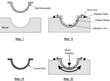
prevent resin from entering the vacuum pump and causing damage. Then, the mould is covered with a flexible plastic sheet. This plastic sheet attaches to the sealant tape to seal the mould and acts as the top half of the mould (Step-II). In addition, if required, the injection and vent lines can also be passed through the plastic sheet provided sufficient sealing is maintained. The vacuum pump evacuates air from inside the mould, thus creating a negative pressure gradient. This negative pressure gradient drives resin from its source through the injection line into the porous reinforcement (Step-III). Once the reinforcement is completely infused, resin injection is stopped while the vent is kept open and resin is allowed to cure before extracting the finished part (Step-IV).
Figure 1.1: General steps of the Vacuum Infusion (VI) process.
The VI process is limited by the maximum achievable vacuum pressure and, in general, gives longer infusion times as compared to resin cure times. Variants of the process employ different means to spread resin faster and thus, speed up the process. In Seemans’ Resin Injection Moulding Process (SCRIMPTM) (Seamann, 1990), a patented and one of the most popular variant of the VI process, a layer of fluid pervious peel-ply and high permeability material (or
5
Figure 2.12: General steps of the Vacuum Infusion (VI) process [8].
Figure 2.12 shows the general steps of the VI process. First, reinforcement is laid on top of a rigid mould bottom half (Step-I). A sealant tape is laid around the periphery of the reinforcement, while injection and vent lines are positioned on top of it. The injection and vent lines pass through the sealant tape to connect to a resin source and a vacuum pump, respectively. Additionally, a resin trap can be added between the vent line and the vacuum pump to prevent resin from entering the vacuum pump and causing damage. Then, the mould is covered with a flexible vacuum bag. This vacuum bag attaches to the sealant tape to seal the mould and acts as the top half of the mould (Step-II). In addition, if required, the injection and vent lines can also be passed through the plastic sheet provided sufficient sealing is maintained. The vacuum pump evacuates air from inside the mould, thus creating a negative pressure gradient. This negative pressure gradient drives resin from its source through the injection line into the porous reinforcement (Step-III). Once the reinforcement is completely infused, resin injection is stopped while the vent is kept open and resin is allowed to cure before extracting the finished part (Step-IV).
18 Chapter 2. State-of-the-art
Resin film infusion (RFI)
Resin film infusion (RFI) is a hybrid process in which a preform is placed in a mould on top of a layer or interleaved with layers of high-viscosity resin film. It has been developed as a cost effective replacement for autoclave process.
In RFI, dry fabrics are laid-up interleaved with layers of resin film supplied on a release paper. The lay-up is vacuum bagged to remove air through the dry fabrics and then heated in an oven to allow the resin to first melt and flow into the air-free fabrics, and then after a certain time, to cure. The lay-up is depicted in Figure 2.13. The result is a uniform resin distribution (even with high-viscosity, toughened resins, because of the short flow distance) and high fibre volumes with low void contents [9, 55].
Figure 2.13: Schematic view of the resin film infusion process [9].
The resin film needs to be stored at -18°C, similar to prepreg materials; how-ever, since sandwiching can be done on demand, only resin films need to be stored at lower temperatures, thus exceeding shelf life results in the loss of only resin films. Furthermore, RFI produced parts have excellent structural properties, excellent dra-pability and a very low void content.
Centrifugal casting
In centrifugal casting, reinforcements and resin are deposited against the inside sur-face of a rotating mould. Centrifugal force holds the materials in place until the part is cured.
The reinforcement, roving or, for small diameters, fabrics, mats or complexes and resin, are introduced into a rotating, cylindrical, metal mould as depicted in Fig-ure 2.14. The resin impregnates the reinforcement under the effect of the centrifugal force and forms, after polymerization, a cylindrical structure. The speed of rotation is increased until the moulding speed is reached, which depends on several factors, such as, the amount and nature of the reinforcement, the thickness and diameter of the part and the viscosity of the resin.
2.2 Manufacturing composite processes 19
Figure 2.14: Schematic view of the Centrifugal Casting process [10].
This process is suitable for the production of hollow parts, such as pipes, with two smooth surfaces. The outside surface of the part, which is cured against the inside surface of the mould, is the finished surface. The interior surface can be given an additional coating of pure resin to improve surface appearance and provide ad-ditional chemical resistance in the part. It is particularly well suited for producing structures with large diameters: pipes for oil and chemical industry installations, water supply, tanks for the storage of wine, milk or chemical products. It is be-ing increasbe-ingly used to produce poles, such as telephone and street lightbe-ing poles. Moreover, centrifugal casting contains volatiles during processing and its productiv-ity per tool is relatively low [10, 56].
Continuous lamination
Continuous lamination is a highly automated process which makes composites in sheet form such as composite glazing, corrugated or flat construction panels, and electrical insulating materials.
Figure 2.15: Schematic view of continuous lamination [10].
As outlined in Figure 2.15, the reinforcement fibres are impregnated with resin and sandwiched between two plastic films. The sheet takes shape under forming rollers and is then guided through pressing and guiding rolls so the desired com-posite lay-up is formed. Typically, high output machines up to 3 meters wide are used in the continuous lamination process. As the material is passed through a
20 Chapter 2. State-of-the-art
heating zone, the resin is cured to form the composite panel. The structure consists of several reinforcement layers depending on strength, stiffness and other required properties.
Panels are automatically trimmed to width and cut to length. Corrugated sheet is produced by forming shoes which hold the compacted sheet in the required shape during cure and special surface effects are created by using embossed car-rier films that are later removed. Both mat reinforcements and rovings chopped by special wide cutters are employed in the process. Polyester and acrylic modi-fied polyesters (for improved water resistance) are the primary resins for continuous lamination [57, 54, 10].
Pultrusion
Pultrusion is a continuous process for manufacturing composites with constant cross-sections or structural profiles having significantly long length. It is widely employed in the composites industry due to its continuous, automated and highly productive nature.
Raw materials are a liquid resin mixture (containing resin, fillers and special-ized additives) and flexible textile reinforcing fibres [58].
382 Manufacturing techniques for polymer matrix composites (PMCs)
© Woodhead Publishing Limited, 2012
carbon or aramid. Pultrusion is an effective process for manufacturing FRP composites parts with uniform cross-section. It is widely employed in the composite manufacturing industry due to its continuous, automated and highly productive nature.
12.1.1 Traditional pultrusion: an overview
The term pultrusion comes from the words ‘pull’ and ‘extrusion’. It is the process where continuous fi bres soaked in a polymer are pulled through a heated die and extruded (Hota et al ., 2009).
From Fig. 12.1 , the pultrusion process starts with the pulling of reinforcing fi bres in the forms of continuous rovings or mats from a series of creels. The fi brous material is fed continuously through a guiding system into a resin bath to get it impregnated. The resin-soaked fi bres are guided to a heater assembly to preheat the fi bre–resin mix while shaping it close to the desired fi nished profi le. The same is then taken into a heated die where curing of thermosetting resin is initiated by the heat. The cured part subsequently leaves the die in the desired shape where it is cut into the required lengths using a cut-off saw without interrupting the continuous pultrusion process (Sharma et al. , 1998).
12.1.2 Historical background
Pultrusion is relatively an old process of manufacturing long FRP com-posites. Goldsworthy is believed to have pioneered the pultrusion process in the early 1950s. In those days the technique was mainly adopted to fab-ricate parts requiring uniaxial performance such as rods, poles, handles, etc.
The process has undergone considerable changes subsequently over the years. The variety and quality of structural profi les has been increasing. In 1960s, there were about 20 manufacturers, primarily in the United States. The number has been continuously growing, and in 2006 it was tallied to 300 pultruders in the world. In addition, the number of users of pultrusion in Asia and Eastern Europe is growing (Jacob, 2006).
Rovings and fabrics
Resin tank Pre-heater Heaters
Heaters
Die
Puller Cutter
12.1 Schematic of pultrusion process.
Figure 2.16: Schematic view of the pultrusion process [11].
While pultrusion machine design varies with part geometry, the traditional pultrusion process concept is described in the schematic shown in Figure 2.16. As depicted in the figure, the pultrusion process starts with the pulling of reinforcing fibres in the forms of continuous rovings or mats from a series of creels. The fibrous material is fed continuously through a guiding system into a resin bath to get it impregnated. The resin-soaked fibres are guided to a heater assembly to preheat the fibre–resin mix while shaping it close to the desired finished profile. The same is then taken into a heated die where curing of thermosetting resin is initiated by the heat. The cured part subsequently leaves the die in the desired shape where it is cut into the required lengths using a cut-off saw without interrupting the continuous pultrusion process.
Some disadvantages exist in the traditional thermosetting and thermoplastic pultrusion processes and so studies have been conducted in various key features and problem areas. These have resulted in a number of pultrusion variants that combine conventional pultrusion and other processes, such as compression moulding and in-jection moulding processes, have gained attention due to the ability to integrate the
![Figure 2.2: Schematic view of the set up inside an autoclave and principal of autoclave curing [2].](https://thumb-eu.123doks.com/thumbv2/123dok_br/15589940.1050487/28.892.192.651.776.992/figure-schematic-view-inside-autoclave-principal-autoclave-curing.webp)
![Figure 2.9: Schematic view of the Compression moulding [5].](https://thumb-eu.123doks.com/thumbv2/123dok_br/15589940.1050487/33.892.186.769.795.988/figure-schematic-view-compression-moulding.webp)
![Figure 2.10: Injection moulding cyclic process [6].](https://thumb-eu.123doks.com/thumbv2/123dok_br/15589940.1050487/35.892.193.738.533.771/figure-injection-moulding-cyclic-process.webp)
![Figure 2.11: General steps of Reaction Injection Moulding (RIM) [7].](https://thumb-eu.123doks.com/thumbv2/123dok_br/15589940.1050487/36.892.139.686.306.578/figure-general-steps-reaction-injection-moulding-rim.webp)
![Figure 2.15: Schematic view of continuous lamination [10].](https://thumb-eu.123doks.com/thumbv2/123dok_br/15589940.1050487/39.892.264.688.746.961/figure-schematic-view-of-continuous-lamination.webp)

![Figure 2.21: Schematic view of SCRIMP [14].](https://thumb-eu.123doks.com/thumbv2/123dok_br/15589940.1050487/45.892.218.725.498.707/figure-schematic-view-of-scrimp.webp)