Universidade de Aveiro Departamento deElectr´onica, Telecomunica¸c˜oes e Inform´atica, 2014
Miguel Nuno de
Sousa Rocha
Sistema de Bloqueio de Computadores
Computer Locking System
Universidade de Aveiro Departamento deElectr´onica, Telecomunica¸c˜oes e Inform´atica, 2014
Miguel Nuno de
Sousa Rocha
Sistema de Bloqueio de Computadores
Computer Locking System
Disserta¸c˜ao apresentada `a Universidade de Aveiro para cumprimento dos requesitos necess´arios `a obten¸c˜ao do grau de Mestre em Engenharia de Computadores e Telem´atica, realizada sob a orienta¸c˜ao cient´ıfica de Dr. Andr´e Ventura da Cruz Marnˆoto Z´uquete, Professor do Departamento de Electr´onica, Telecomunica¸c˜oes e Inform´atica da Universidade de Aveiro
o j´uri / the jury
presidente / president Prof. Dr. Tom´as Ant´onio Mendes Oliveira e Silva Professor Associado da Universidade de Aveiro
vogais / examiners committee Prof. Dr. Andr´e Ventura da Cruz Marnoto Z´uquete Professor Auxiliar da Universidade de Aveiro (orientador)
Prof. Dr. Carlos Nuno da Cruz Ribeiro
agradecimentos / acknowledgements
Primeiro, gostaria de agradecer ao meu orientador Professor Andr´e Z´uquete pela sua orienta¸c˜ao e motiva¸c˜ao durante todo o per´ıodo de realiza¸c˜ao deste trabalho.
Aos meu pais e familiares, obrigado pelo investimento na minha forma¸c˜ao como homem, pela exigˆencia e por todo o apoio.
Por ´ultimo, um agradecimento a todos os meus amigos em especial ao meu colega de laborat´orio Lu´ıs Silva pelas discuss˜oes, desabafos e brincadeiras.
Resumo O uso de v´arios dispositivos computacionais por pessoa est´a a aumentar cada vez mais. Hoje em dia ´e normal dispositivos m´oveis como o smart-phone, tablet e computador port´atil estarem presentes no quotidiano das pessoas e em muitos casos as pessoas necessitam de realizar tarefas na sua vida profissional nestes dispositivos. Isto apresenta tamb´em um prob-lema, como estes dispositivos acompanham o utilizador no dia a dia e pelo facto de muitas vezes terem um valor monet´ario elevado faz com que estes dispositivos sejam suscept´ıveis a roubos.
Esta tese introduz um sistema de bloqueio de computadores que se distingue dos sistemas similares existentes porque, (i) ´e desenhado para funcionar in-dependentemente do(s) sistema(s) operativo(s) instalado(s) no computador port´atil ou no dispositivo m´ovel, (ii) depende de um driver do firmware que concretiza a opera¸c˜ao de bloqueio fazendo com que seja resistente contra formata¸c˜ao do dispositivo de armazenamento ou qualquer outro ataque que tenho por base a utiliza¸c˜ao de software. ´E explorado ent˜ao o funcionamento de um dispositivo que tenha um firmware que respeita a especifica¸c˜ao Un-fied Extensible Firmware Interface (UEFI) assim como a programa¸c˜ao de drivers para este tipo de firmware. Foi tamb´em desenvolvido um protocolo de seguran¸ca e s˜ao exploradas v´arias t´ecnicas criptogr´aficas passiveis de serem implementadas.
Abstract The use of multiple computing devices per person is increasing more and more. Nowadays is normal that mobile devices like smartphones, tablets and laptops are present in the everyday life of a single person and in many cases people use these devices to perform important operations related with their professional life. This also presents a problem, as these devices come with the user in everyday life and the fact that often they have a high monetary value means that these devices are susceptible to theft. This thesis introduces a computer locking system that distinguishes itself from existing similar systems because (i) it is designed to work independently of the Operating System(s) installed on the laptop or mobile device, (ii) depends on a firmware driver that implements the lock operation making it resistant to storage device formats or any other attack that uses software operations. It is also explored the operation of a device that has a firmware that follows the Unified Extensible Firmware Interface (UEFI) specification as well as the development of drivers for this type of firmware. It was also developed a security protocol and various cryptographic techniques where explored and implemented.
Contents
Contents i
List of Figures v
List of Tables vii
1 Introduction 1 1.1 Objective . . . 2 1.2 Contribution . . . 2 1.3 Document Structure . . . 3 2 Context 5 2.1 UEFI . . . 5 2.1.1 UEFI Structures . . . 6
UEFI System Table . . . 6
Handle database . . . 7
Protocols . . . 8
2.1.2 UEFI Driver model . . . 9
Driver Binding Protocol . . . 11
Service Binding Protocol . . . 11
2.1.3 UEFI System Partition . . . 12
2.2 Cryptography . . . 13
2.2.1 Cryptographic Hash Function . . . 13
2.2.2 Message Authentication Code . . . 13
3 Related Work 17
3.1 Intel Anti-Theft Technology . . . 17
3.2 Absolute Computrace . . . 19
3.3 Prey . . . 22
4 System Architecture 25 4.1 Overview . . . 25
4.2 Low level locking: UEFI Driver . . . 26
4.2.1 Computer States . . . 26
4.2.2 Cryptographic protections . . . 27
4.2.3 CuCo context variables . . . 30
4.2.4 Ticket Structure . . . 31
4.2.5 Boot sequence . . . 33
4.2.6 Blocked Screen Stage . . . 33
4.3 Administration . . . 36
4.3.1 System Architecture . . . 36
4.3.2 CuCo Server . . . 36
Database . . . 36
Administration Interface . . . 36
Tickets Web Service . . . 37
4.4 Desktop Application . . . 37 4.5 Exploitation flow . . . 37 5 Implementation 39 5.1 Testing environment . . . 39 5.1.1 QEMU . . . 40 5.1.2 OVMF . . . 40 5.2 Implementation frameworks . . . 42 5.2.1 GNU-EFI . . . 43 5.2.2 TianoCore EDKII . . . 45
5.2.3 Java and Apache Tomcat . . . 46
5.3 UEFI Drivers . . . 47
5.3.1 UEFI Hashing Driver . . . 48
UEFI Variables . . . 51
UEFI Time Services . . . 52
UEFI Memory Allocation Services . . . 52
UEFI Media Access Services . . . 52
Ticket Validation . . . 53
GNU-EFI Library Functions . . . 53
Consuming Hashing Services . . . 54
5.3.3 Detailed Ticket Structure . . . 54
5.4 Administration . . . 56
5.4.1 WebServices and Web Managment Interface . . . 56
5.4.2 Desktop Application installation script . . . 58
6 Conclusion 61 6.1 Summary . . . 61
6.2 Final Conclusions . . . 62
6.3 Future Work . . . 63
List of Figures
2.1 Handle database. Retrieved from [1] . . . 8
2.2 Software Service Relationships. Retrieved from UEFI Specification . . . 10
2.3 rEFInd Boot Manager menu. Retrieved from [2]. . . 12
2.4 Message authentication using a MAC mechanism. . . 14
3.1 Intel Anti-Theft locking screen. Retrieved from [3] . . . 18
3.2 Intel Anti-Theft Architecture. Retrieved from [3] . . . 19
3.3 The Absolute Computrace UEFI Driver. . . 20
3.4 On some platforms Absolute Computrace module can be enabled or disabled. Retrieved from [4] . . . 22
3.5 Different types of devices running Prey. . . 23
4.1 The three developed components: UEFI Driver, Desktop Application and Web Application . . . 26
4.2 CuCo States. . . 27
4.3 Certification Chain. . . 29
4.4 CuCo Booting Process Flowchart. . . 35
4.5 System Architeture . . . 36
5.1 UEFI Boot Process. (retrieved from [5]) . . . 41
5.2 Qemu emulator running TianoCore OVMF. . . 42
5.3 EDKII Platform Build Process Flow. (retrieved from [6]) . . . 46
5.4 The driver that implements the EFI HASH PROTOCOL in the left and the CuCo Driver that implements our booting protocol on the right. . . 48
5.5 Simplified booting process of a UEFI platform. Our CuCo Driver runs on every boot and before the operating system. . . 50
5.6 CuCo Server components. The Web interface at left and the Web services interface on the right . . . 57 5.7 The contents of the desktop application JAR file. . . 59 5.8 The customized package that is distributed for every user. . . 60
List of Tables
2.1 UEFI System Table fields and description. . . 7
2.2 UEFI Boot Services used to manage protocols. . . 9
2.3 UEFI Boot Services used to query the handle database. . . 9
4.1 Ticket’s fields. . . 32
5.1 QEMU command line options used to boot OVMF. . . 40
5.2 GNU Compiler options used to compile UEFI compatible code. . . 44
5.3 Linker options used to build a UEFI executable. . . 44
5.4 Two examples of a Start and a Normal Ticket. . . 56
Chapter 1
Introduction
With the increase of stolen laptops and compromised data, lock and anti-theft mechanisms are becoming more and more important. Several anti-theft mechanisms exist, such as Intel Anti-Theft and Absolute Lojack, but they are not widespread. Intel Anti-Theft [7] relies on a mini-computer system installed on the motherboard and running concurrently with the main system, which makes this mechanism very expensive and, therefore, available only in higher-end equipment. Absolute Lojack [8] makes use of UEFI but is only effective when the computer runs a Windows operating system. There are also software-only solutions for laptops and mobile devices such as Prey [9] but they are easily removable by formatting or replacing the hard drive.
UEFI (Unified Extensible Firmware Interface) is a software interface specification that was conceived to replace the old BIOS (Basic Input/Output System). It describes how the communication is performed between the operating system and the computer firmware. This specification provides boot and runtime services and protocols that are available to the operat-ing system bootloader and to the operatoperat-ing system itself, makoperat-ing the boot process a standard process. The same operating system can boot from several UEFI supported platforms without the need to change the code of the operating system bootloader.
UEFI specification also describes a well-defined driver model. UEFI drivers are blocks of code that are meant to provide an abstraction layer between UEFI modules and hardware devices or software services specific to the platform (e.g. USB bus drivers or SCSI drivers). It is worthwhile to say that the purpose of these drivers is to be used only in a preboot environment and not after the loading of the operating system, where more efficient drivers are normally used.
1.1
Objective
The objective of this work was to create a computer locking mechanism that can run on any UEFI-enabled device independently of the booted operative system. The UEFI locking mechanism would be part of a larger computer protection ecosystem designed primordially for a computer leasing business. Such ecosystem encompasses several other components, such as (i) applications to run on the operating system of the protected computers, for interacting with the computer owner, and (ii) protection management services for controlling locking and unlocking actions. In this work we developed all these components, but a greater effort was devoted to the low-level UEFI locking mechanism.
It was necessary to explore the preboot environment and functionalities of a UEFI sup-ported device, specifically its driver model, protocols and services.
Regarding all the security issues that can happen in a system of this nature and considering the limitations of a UEFI Driver it was necessary to create an appropriate high level security protocol that describes all the operations that our system must follow.
In the conception of this protocol we kept in mind that our system must have the ability to be enabled and disabled. The unblocking process was also a concern since it must be an easy operation for a common laptop user.
So, we tackled the following major challenges:
• What functionalities does a UEFI environment provide that can be effective in the conception of our system?
• What kind of protocol approach can we use taking in consideration the absence of network connection in a preboot environment?
• What cryptographic, symmetric or asymmetric, protection should be used and what are the consequences of one or another?
• How can we manage time-related lockings on laptops disconnected from the Internet where the local clock can be manipulated?
1.2
Contribution
The main contribution is a system that allows a laptop to be locked after some time upon a failure in the fulfilment of contractual conditions (e.g. lease payment). Furthermore, the
system includes several unlocking possibilities for dealing with personal difficulties to fulfil the above mentioned conditions.
Studies about the booting process of a computer and specifically to UEFI and UEFI Driver Model were performed in order to create two UEFI Drivers: (i) a driver that provides cryptographic functionality to other drivers or applications; (ii) a driver that runs on every boot and implements the designed security protocol and if necessary prevents the operating system bootloader to load.
A security protocol was conceived based on a ticket leasing system and an online server was created for exploring the computer locking mechanism for clients missing leasing payments. The purpose of this server is to handle all the clients running this system and, for each one, to manage the tickets and leasing details.
Since the access to the server from the UEFI driver is not convenient, a desktop application was created to request tickets from the server and to write them in the ESP (EFI System Partition) that is a non volatile memory location that both UEFI modules and the operating system can access. In the booting process, the UEFI Driver will then read the ticket from the ESP and execute the necessary actions which will lead to two final decisions: prevent the operating system boot loader from loading and enter a locking state or continue the normal boot process. The desktop application is also used to provide feedback about the leasing contract such as alerts or notifications about the proximity of a locking deadline.
The developed system is called CuCo and it was designed for Inforlandia [10], a Portuguese company with a business area related with computer leasing. Since the main component of our system requires to be flashed in the firmware memory, this work was also developed with the partnership of American Megatrends [11], a motherboard manufacturer.
1.3
Document Structure
This chapter has presented an overview of this thesis, namely the objectives and the technical contributions. The rest of this document is arranged as follows: Chapter 2 con-textualizes the reader regarding some main concepts and technologies that were needed in the conception of this work. In Chapter 3 we provide an analysis of three related existing anti-theft systems. Chapter 4 presents the architecture of our system including the several components and protocols. In Chapter 5 we present the implementation details as well as useful information about UEFI environment. Finally in Chapter 6 we summarize our work and provide possible directions for future work.
Chapter 2
Context
With the intention of contextualizing the reader, we provide an explanation of the several technologies required in the conception of this work as well as a review on security techniques that were, naturally, necessary to develop a secure system.
We begin by describing the technology that was more difficult to study, UEFI. We will give an overview regarding the characteristics of this technology as well as detailed information from a developer’s point of view.
Finally, we explain three well known cryptographic strategies: Message Authentication Codes (MAC) and Digital Signatures used to authenticate our ticket files and Cryptographic Hashing Functions used in the computation of unlocking codes.
2.1
UEFI
The software that runs when a computer is first powered on is called firmware [12]. It is responsible for testing (POST - Power-on self-test) and initializing the various hardware devices. From a perspective of the operating system, it also creates an abstraction layer from hardware devices through the use of pieces of code typically called drivers.
EFI (Extensible Firmware Interface) is an interface specification first developed by Intel until 2005. Since that time, EFI is called UEFI (Unified Extensible Firmware Interface) and it is maintained by the Unified EFI Forum which is a group of several companies from hardware producers to software companies [13].
UEFI describes: (i) the booting process phases of a computer (PI - Platform Initialization); (ii) programming interfaces of the several platform devices, abstracting hardware details from an operating system (OS).[14]
The extensibility of UEFI is the feature that allowed us to realize this work and it is accomplished with the use of drivers running in a preboot environment. UEFI describes the UEFI Driver Model (Chapter 2.5 of UEFI Specification) that defines a set of rules that must be followed in the conception of a UEFI Driver, providing three main advantages:
• Standard driver development;
• Simple driver loading/unloading performed by an entity called Boot Manager; • Standard communication between drivers.
UEFI defines a set of services to provide a abstraction layer of its interfaces. These services are used by UEFI images (including UEFI drivers) and are divided in two categories:
• Boot Services - These services can be accessed only during the preboot environment; • RunTime Services - These services can be used after the boot environment by a
UEFI-compilant operating system.
Some Boot Services provided by UEFI are Memory Services used to allocate and free memory reserved from UEFI firmware, Protocol Handler Services used to install, uninstall and locate protocols and Event and Timer Services used to create, wait or close events or timers.
Runtime Services are services that are useful for both the computer firmware such as drivers and for the operating system. Such services include Time Services used to set and get the time of the computer clock, Variable Services to get and set UEFI variables and Virtual Memory Services used to manage virtual memory mapping.
2.1.1 UEFI Structures
This section describes some aspects and key concepts in UEFI programming environment that are necessary to understand how to develop a UEFI Driver or UEFI application.
UEFI System Table
This is the main data structure in UEFI. UEFI Drivers and applications use this data structure to access UEFI boot/runtime services as well as services provided by protocols.
The difference between runtime and boot services are that runtime services can be accessed after the operating system is loaded. Both take the form of a table that contains pointers to the services (functions).
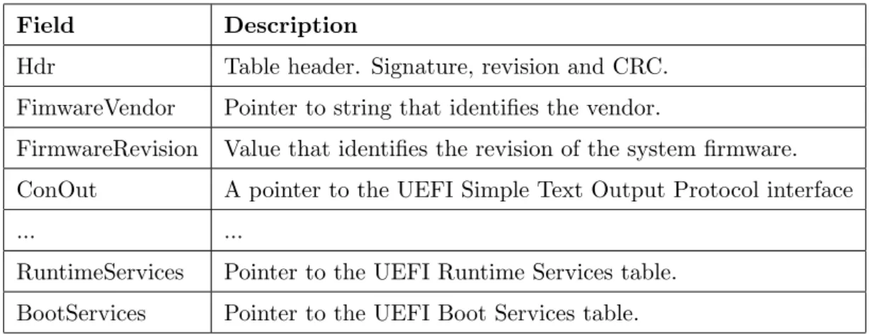
Protocol services are used to provide an extensible firmware interface that can grow over time. UEFI specification itself, describes a set of protocols but only a few are mandatory to be implemented in the UEFI core firmware by platform vendors. These protocols are identified by a GUID (Global Unique ID) that is a 128-bit number. Although UEFI specification defines a set of protocols, additional protocols can be added by UEFI drivers, thus providing more features to UEFI firmware. Bellow there is a table that represents the UEFI System Table [15], particularly, some of its fields and description for each one.
Field Description
Hdr Table header. Signature, revision and CRC. FimwareVendor Pointer to string that identifies the vendor.
FirmwareRevision Value that identifies the revision of the system firmware. ConOut A pointer to the UEFI Simple Text Output Protocol interface
... ...
RuntimeServices Pointer to the UEFI Runtime Services table. BootServices Pointer to the UEFI Boot Services table.
Table 2.1: UEFI System Table fields and description.
A pointer to the this table is passed to UEFI Drivers and Applications as part of its entry point. The following code prints ”Hello World” in the console. It shows how to use the UEFI Simple Text Output Protocol that can be accessed through the UEFI System Table.
Listing 2.1: An example of how to use a UEFI Boot Service
#include <efi.h>
EFI_STATUS main(EFI_HANDLE ImageHandle, EFI_SYSTEM_TABLE *SystemTable) {
SystemTable->ConOut->OutputString(SystemTable->ConOut, L"Hello World\r\n");
return EFI_SUCCESS; }
Handle database
The handle database is a global data structure that can be accessed by any UEFI ex-ecutable. It holds UEFI handles that are associated with one or more protocols. A UEFI
handle can represent UEFI drivers/applications, physical devices or software services. In order to provide a safe start/stop of UEFI Drivers the handle database also contains a list of the components which are consuming the protocols.
The handle database is a list of groups of protocols that are represented by a handle. The same protocol can be present in several handles in the handle database but a handle cannot have duplicate protocols (GUIDs).
Figure 2.1: Handle database. Retrieved from [1]
The handle database is accessed by UEFI Drivers or Applications. They access the handle database to use protocols (consumers) or to register protocols (producers).
Protocols
Apart from Runtime Services and Boot Services, UEFI defines Protocols. Protocols are interfaces used by UEFI Drivers and Applications to communicate with each other. Like most of services present in UEFI, protocol interfaces are typically a table of pointers pointers. Protocols are attached to a handle and are identified by a GUID (Global Unique Identifier). UEFI Drivers that are producers can register or deregister protocols interfaces in the handle database using the following UEFI Boot Services:
Name Description
InstallProtocolInterface Install a protocol interface on a device handle. UninstallProtocolInterface Removes a protocol interface from a device handle. InstallMultipleProtocolInterfaces Installs one or more protcol interfaces onto a handle. UninstallMultipleProtocolInterfaces Unisntalls one or more protocol interfaces from a handle.
Table 2.2: UEFI Boot Services used to manage protocols.
The registration services requires that the drivers or applications provide both the protocol interface structure as well as the GUID. In the removing process only the GUID is needed.
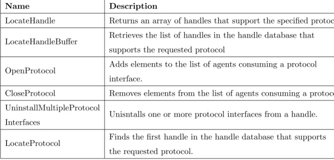
UEFI Boot Services table also provides services for consumer UEFI Drivers or Application to use the protocols present in the Handle Database. Such services include:
Name Description
LocateHandle Returns an array of handles that support the specified protocol. LocateHandleBuffer Retrieves the list of handles in the handle database that
supports the requested protocol
OpenProtocol Adds elements to the list of agents consuming a protocol interface.
CloseProtocol Removes elements from the list of agents consuming a protocol. UninstallMultipleProtocol
Interfaces Unisntalls one or more protocol interfaces from a handle. LocateProtocol Finds the first handle in the handle database that supports
the requested protocol.
Table 2.3: UEFI Boot Services used to query the handle database.
There are also services to retrieve the list of agents that are currently consuming a protocol interface or services to query the handle database to determine if a specific handle supports a specific protocol.
2.1.2 UEFI Driver model
The UEFI Driver Writer’s Guide [6] defines four types of UEFI Drivers: • UEFI Driver that follows the UEFI Driver Model;
• Initializing driver; • Root bridge driver; • Service driver.
A initializing driver is a driver that runs in the booting process of a UEFI firmware and does initialization operations. It is removed from the system memory after executing.
Root bridge drivers are associated with physical devices and are responsible for creating controller handlers for the root bridge controllers sush as PCI devices.
Service drivers do not represent physical devices, they are typically used to produce pro-tocols in service handles.
UEFI Specification defines the UEFI Driver Model which is a set of rules that a driver must follow. Such rules allow the UEFI firmware to have more control over the several drivers, their loading/unloading into/from memory. Those rules take the form of protocols that a UEFI driver must register in the handle database.
Bellow there is the list of required protocols that a driver that produce protocols that need to be available to more than one consumer must register in the handle database:
• Driver Binding Protocol - This protocol provides functions for starting and stopping the driver;
• Service Binding Protocol - This protocol is needed to allow a protocol to be con-sumed by more than one entity.
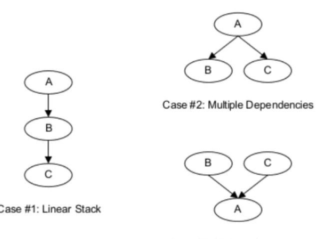
The Driver Binding Protocol is appropriate for a driver intended for hardware devices or hardware bus controllers because UEFI Specification states that each protocol can have only at most one consumer thereby preventing multiple drivers from managing the same hardware device or bus (cases #1 and #2 of figure 2.2). However in order to provide a UEFI driver the ability to be used by more than one entity, which is the typical situation of a driver that produces software services represented by case #3 of of figure 2.2, a UEFI driver must also implement the UEFI Service Binding Protocol.
Driver Binding Protocol
In the driver entry point, a UEFI driver that follows the UEFI Driver Model, must register the Driver Binding Protocol in the handle database. The Driver Binding Protocol consists of the following services:
• Supported() - It is used by the UEFI Driver loader to check if the drivers supports a given controller. In our case, since our drivers do not represent physical devices in the platform, this function is only useful to test if the driver was already started or not; • Start() - This function is used to install the protocol interface;
• Stop() - This function is used to uninstall the protocol interfaces installed by this driver the Start() was called.
Service Binding Protocol
A driver that only implements the Driver Binding Protocol can be consumed at most by one consumer which is useful to prevent multiple entities from trying to manage the same controller but when a driver installs protocols interfaces that are meant to be consumed by several consumers it needs to install the Service Binding Protocol. This is a typical situation of a driver that provides software services to other drivers.
The Service Binding Protocol interface consists of the two services bellow: • CreateChild() - Creates a new handle with the associated protocol installed; • DestroyChild() - Uninstalls the associated protocol and the handle is freed.
This kind of drivers must produce both Service Binding Protocol and Driver Binding Protocol. The Service Binding Protocol is installed in the Driver Binding Protocol Start() function and uninstalled in the Stop() function.
2.1.3 UEFI System Partition
As the name implies, the UEFI System partition (ESP) is a disk partition that every platform running UEFI firmware must contain on its hard drive in order to boot a operating system (booting from removable devices is also supported).
The ESP is formatted in the FAT (File Allocation Table) file system architecture and is the only file system that UEFI firmware supports. Since FAT is a simple legacy file system, many operating systems support it and therefore, it can be mounted at OS time and user-land applications can access it. This features makes the ESP a perfect communication channel between Operating Systems and UEFI firmware through the use of files.
UEFI Specification states that the boot loaders for all operating systems installed in the hard drive must be stored in the ESP. It can also contain UEFI drivers or UEFI utility programs such as a UEFI Shell, or memory checking programs. This allows the existence of boot managers that auto-detects the operating systems installed on the platform by searching the corresponding bootloaders at boot time. Such boot managers provides a menu that allows the user to select the operating system that he wants to boot.
Figure 2.3: rEFInd Boot Manager menu. Retrieved from [2].
rEFInd [2] is a boot manager for UEFI platforms that auto detects the installed Operating Systems by searching the bootloares that are present in the ESP.
2.2
Cryptography
In this section we provide background information related with two cryptographic tech-niques that were used in the implementation of this work.
2.2.1 Cryptographic Hash Function
Cryptographic Hash Functions are functions that take an arbitrary size of bytes as the input and transforms that set in a fixed size set of bytes (typically called hash value). This functions are considered one-way functions because, due to its internal operation, it is ”very hard” to invert the result of a given input. In the context of cryptography these functions are used along with other security techniques to provide the integrity and originality of a message. A ideal cryptographic hash function has the three main properties [16]
• Preimage Resistance: Given hash value H it is very hard to find any message M such that H = hash(M);
• Second Preimage Resistance: Given a message M it is very hard to find a second message M’ such that hash(M) = hash(M’);
• Collision Resistance: It is very hard to find two messages M and M’ such that hash(M) = hash(M’).
2.2.2 Message Authentication Code
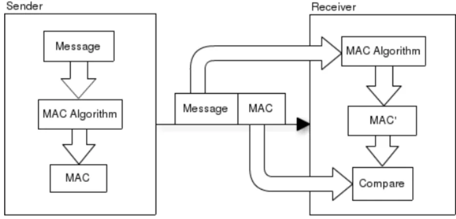
Message Authentication Code algorithms are symmetric key based techniques that are used to guarantee the integrity and originality of a message. A MAC is a value that is transferred along with the message that authenticates. It is calculated using a symmetric key that is known to both the sender and receiver of the message.
Unlike digital signatures, MAC does not prove that a message was sent by one entity but that a message was sent by one of the entities that possess the key.
A MAC can be generated using several techniques, namely, (i) block ciphers, (ii) stream ciphers, (iii) cryptographic hash functions. The last one was used in the conception of this work, specifically, HMAC algorithm.
The operation of generating and verifying a authenticated message is as follows: 1. The sender generates the MAC M for the text T and with the key K;
2. The sender sends T along with M;
3. The receiver uses T to calculate a MAC M’ with the key K;
4. The receiver compares M’ with M. If they match, then the message was generated by a trusted entity (a entity that knows K).
Figure 2.4: Message authentication using a MAC mechanism.
2.2.3 Digital Signatures
Like MACs, digital signatures are blocks of data that are, typically, sent along with the original message to guarantee its integrity and originality. Digital signatures are closely linked to asymmetric cryptography in that the sender of the message holds a private and a public key and the operations of signing and verifying the signature are based in asymmetric algorithms.
The operation of generating and verifying a digital signature is as follows:
1. The sender generates an hash of the original message using a cryptographic hashing function;
2. The sender encrypts the resulting hash with his private key;
3. The sender sends the encryption result (digital signature) along with the original mes-sage;
4. The receiver generates an hash of the original message, H, using the same cryptographic hashing function;
5. The receiver decrypts the received digital signature, H’, and compares H’ with H. If they match, then the message was generated by the entity that holds the private key. Since an entity that issues digital signatures is associated with a asymmetric key pair, digital signatures, unlike MACs, offers the non-repudiation property that guarantees that a digital signature is generated by the entity that holds the private key associated with the public key used to verify the signature.
Chapter 3
Related Work
In this chapter we enumerate three commercial solutions that provide identical function-alities to our system. For each one, we give an overview of its features as well the operating mode.
3.1
Intel Anti-Theft Technology
Intel Anti-Thef is part of Intel vPro [17] family products and is a hardware-based tech-nology that is intent to fight the robbery of laptops. The system is a partnership between Intel and third party software companies.
Intel Anti-Theft Service provides:
• The tracking of a laptop running this service; • Protection of data stored in the laptop’s hard drive; • Remotely lock the laptop.
Regarding the laptop location tracking, when the machine connects to the internet it will send the public IP address to the main server, the server will use IP address geolocation services in order to find an approximate location of the client laptop. Relying on IP address for geolocation is not accurate and several clients complaint about the certainty of this feature. Intel AT also provides protection of data stored in the hard drive by providing a directory (called secure vault) on the hard drive that will be encrypted by the software running in the operating system. The encryption key (they call it Blob) used to encrypt the files is stored in a secure hardware location and if the laptop is in the locked mode the key is inaccessible.
The laptop periodically connects to the Anti-Theft Server to ask for commands. If the laptop is lost of stolen the IT administrator sends a lock command (poison pill) that will prevent the operating system from booting and will show a locking display with a custom message to indicate that the laptop is locked. The laptop is also locked if it does not access the central server for a certain configurable period of time.
Figure 3.1: Intel Anti-Theft locking screen. Retrieved from [3]
Since Intel is mainly a hardware company, its contribution in this system is to provide the hardware capabilities needed to lock the computer and to store secret information but the system administration part is performed by Independent Sofware Vendors (ISV) that are software companies that work in the security are. ISV are responsible for implementing the Central Anti-Theft Server and the Agent that runs in the operating system. Some ISV are: [3]
• McAfee [18];
• Norton Antivirus [19]; • Absolute Computrace [8].
ISVs are responsible for managing the several laptops running Intel AT as well as certain details of the locking system. All of them run only in the Windows Operating System making this technology useful only for devices running this OS.
As we can see in the architecture, the Intel Anti-Theft enabled laptop is periodically sending command requests to the ISV central server through the ISV anti-theft agent that
Figure 3.2: Intel Anti-Theft Architecture. Retrieved from [3]
runs in the operating system. The server will send commands to the laptop as an answer for that requests and the laptop hardware/firmware will take the actions triggered by those commands.
Intel announced that Anti-Theft Service will be terminated in January 2015 and it stopped accepting new subscriptions in January 2014.
3.2
Absolute Computrace
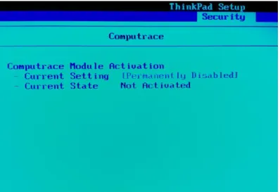
Absolute Computrace [8] is a laptop anti-theft solution developed by Absolute Software and it can lock, track and protect the data of stolen mobile devices running Windows operating system.
This solution relies in 3 main software/firmware components: • UEFI Driver / BIOS Option ROM;
• Client Agent running in the operating system; • Central Server.
In order to support different computer firmware environments, Absolute Computrace de-veloped both a BIOS Option ROM and a UEFI Driver. They are integrated in the computer
firmware stored in the main board ROM memory by the OEM. The BIOS Option Rom is intended for old computers running the legacy BIOS system, while the UEFI Driver is in-tended for UEFI enabled platforms. Although they are different components in terms of implementation, they have the same two main functions:
• Lock the platform if necessary; • Install the Client Agent.
This component has a somewhat unusual behaviour considering the operations performed by a typical firmware driver in a preeboot environment. It contains a Windows executable (Agent) that will be installed, secretly, in the Windows Operating System. In more detail, this driver does the following operations: [20]
1. Find, on the hard drive, the partition where Windows OS is installed. 2. Replace authochk.exe Windows executable with a modified one.
When Windows OS is booting it will run the modified authochk.exe executable. This modified version of authochk.exe will do the following:
1. Exctract a windows binary (rpcnetp.exe) that is embedded in the modified authochk.exe 2. Create a new entry in the local system registry that will run rpcnetp.exe.
Figure 3.3: The Absolute Computrace UEFI Driver.
rpcnetp.exe will now run as a Windows service and it will connect to the Absolute Server and wait for commands, such commands can be the installation of more software, encryption of data or locking the device.
Although these techniques do remember malicious software, they allow the OS software agent to be easily installed and without human intervention but on the other side they are also operating system dependent and if Absolute decides to support other operating systems they have to create a UEFI Driver for each operating system they want to support or they have to greatly modify the current driver.
Regarding the architecture, this system is very similar to Intel Anti-Theft architecture in terms of components and cooperation between them. As already stated, there are three main components:
• UEFI/BIOS Component - This is the component that performs the locking proce-dure. It has the shape of a Option ROM when the lapton is running BIOS or a UEFI Driver when the laptop is running UEFI;
• Agent - This is the component that runs in the Operating System (Windows) and performs the communications with the UEFI/BIOS component and the Central Server. It is installed in a secret manner without the user’s intervention or permission;
• Central Server - This is the Absolute Central Server where all the clients are period-ically connecting and waiting for commands.
The agent is periodically connecting to the Absolute Central Server waiting for commands, such commands can be lock the device, encrypt files or delete data. It will also provide tracking information such as the public IP address where the device is connecting from.
On the server side an IT administrator can have access to several computers running this server and for each one it can manage several details.
Figure 3.4: On some platforms Absolute Computrace module can be enabled or disabled. Retrieved from [4]
3.3
Prey
Prey [9] is a anti theft open source solution developed by Fork, Ltd [21]. It is a multi-platform software that is intended for the major mobile devices operating systems, namely, Windows, Mac OS, Linux, Android and iOS. Its features include remotely locating and locking the lost or stolen device as well as recovering or deleting data.
Prey is a solution that relies in two components. An agent that runs on top of the mobile device Operating System and a central server. The agent software is open source and is written in Node.js [22] with the exception of the Android and iOS agents that are written in their native languages. The official central server (host) is proprietary but an small open source server application written in Ruby [23] is available.
In terms of operation, the agent regularly sends HTTP [24] requests to the central server web service, in response to this requests the server may send several types of commands such as locking commands or request information.
When prey is running in a laptop it provides the location using the wifi network and triangulation techniques. On mobile devices it uses the built-in GPS (Global Positioning Sensor) sensor. The data transfers between the agent and the server is encrypted using SSL tunnelling.
The central server provides a web interface where the user can remotely manage each device. Some features that are provided by the web interface include:
Figure 3.5: Different types of devices running Prey.
• Get the device location - The laptop or mobile device tracking information shown in a map;
• Webcam and Desktop screenshot - The screen shot of the desktop can be useful to discover the thief identity as well as the screenshot of the web cam can be also advantageous to discover the thief face and therefore provide such information to the police;
• Hardware scanning - Changes in the hardware can be detected;
• Screen locking - The user can remotely lock a device and the unlocking procedure requires a password that must be previously set.
Prey requires a monthly payment in order to fully benefit from all the features provided by this service. There are several payment plans and what distinguishes them is the number of devices where prey can be installed. For an ordinary user a plan that allows 3 devices may be sufficient considering that this user only needs Prey to manage a small number of devices
(i.e Laptop, Smartphone and tablet) while a company that has many devices can benefit from a plan that allows the use of many devices.
The fact that Prey agents are open-source and their code is publicly available is a great advantage because it allows third parties to analyse the code and ensure that this software does not contain privacy issues that can sometimes be a problem in this type o software. Unlike the Intel Anti-Theft and Absolute Computrace, Prey does not require a hardware of firmware component in order to perform the locking operation, while this is an advantage as it allows the installation of Prey on any common device without having to have special hardware or firmware capabilities, it is also a big disadvantage because it allows an attacker to completely remove this software whether the device is locked or not by simply replacing or formatting the hard-drive.
Chapter 4
System Architecture
In this chapter we present the architecture of our system in terms of components and the protocols followed by such components.
4.1
Overview
Since we want that our locking mechanism works independently of Operating System and given the increased spread of UEFI platforms and its extensibility, the main locking component has the shape of a UEFI driver that runs, unconditionally, on every boot before the Operating System and implements the designed protocol.
Due to the limitations of a UEFI environment, namely the lack of a network access, and the need of a central management unit, our system relies in two more components: a Desktop Application and a Web Application. The desktop application runs on top of the Operating System on every laptop and the Web Application runs on a central server. All the laptops interact with the central server through the desktop application.
Our system implements a protocol based in a leasing system supported by the use of ticket files that are periodically imported by client machines. Those ticket files are issued by an authorized authority (CuCo Server) and are used by the UEFI Driver to follow the protocol. Ticket files contains time fields that states when a ticket/lease is expired as well as elements that guarantee its integrity and authenticity. Depending on the time constraints for each leasing contract, a desktop application has to periodically fetch new tickets with a certain period of time in order to update the system before the current ticket expires.
Operating System UEFI Firmware UEFI Driver Desktop App. CuCo Laptop Web Application CuCo Server Internet
Figure 4.1: The three developed components: UEFI Driver, Desktop Application and Web Application
4.2
Low level locking: UEFI Driver
As previously stated, the low level locking is preformed by a UEFI Driver that must be embedded in the UEFI firmware by an OEM (Original Equipment Manufacturer) in order to prevent the laptop user from removing the UEFI Driver. This driver must run on every boot and also maintain an internal state across reboots supported by a set of context variables.
This section explains the internal operation of our driver.
4.2.1 Computer States
In order to provide the system with the capability to be easily enabled or disabled by an authorized entity, our UEFI Driver follows a state machine behaviour where there are essentially two states:
• FREE: This is the state of CuCo upon the flashing of the UEFI and the cleaning of all CuCo state variables. This is also the state of CuCo upon the end of a leasing contract (with a Freedom Ticket). Once in this state, the machine boots an ordinary operating system without any further CuCo activity. From this state a computer seller can enter the LEASED state prior to sell the machine under a leasing contract. Furthermore, a computer owner can also voluntarily do the same for benefiting from some lease-based protection. In both cases, the transition decision must be authorized in boot time by interacting with the UEFI and can only happen after detecting the presence of a Start Ticket;
Ticket. Once in this state, it can only change to the FREE one upon reception of a Freedom Ticket.
Figure 4.2: CuCo States.
Firmware updates can only be performed by authorized entities and should keep the state variables unchanged.
When in a LEASED state, CuCo can either boot normally or enter a temporary blocked sub-state. This sub-state requires a direct (oral, Internet, etc.) contact with the ticket provider in order to solve the problem that originated the blocking condition. Upon a suc-cessful contact, a suitable unblocking code should be provided to CuCo for proceeding with a normal boot operation. Each unblocking code can be used in only one boot sequence; different boot sequences require different unblocking codes.
4.2.2 Cryptographic protections
In the LEASED state the CuCo module only accepts state changes from inputs prop-erly authenticated (generated by a remote lease manager). We foresee two ways to do this authentication:
1. With a per-machine, secret symmetric key shared with the lease manager. In this case, a unique machine key must be provided (in a ticket) when the state changes from FREE to LEASED.
2. With a per-lease manager, asymmetric key pair. In this case, the public key of a top certification entity must be provided (in a ticket) when the state changes from FREE to LEASED. We are foreseeing that leasing companies would have a top certification entity, in a very well protected place (e.g. a vault) and an intermediate certification entity for the daily ticket issuing.
In both cases, we call this key the Ticket Authentication Key (AK). This key is installed in the firmware memory upon the installation of the start ticket and the transition to the LEASED state.
If AK is symmetric each ticket is associated with a symmetric key that both the CuCo and the ticket issuer knows. If AK is asymmetric the public part of the key of the top certification authority is installed in the firmware and more complex certification strategies can happen (similar to CA certificates [25]). We can have a chain of certification entities and in this case the tickets must contain the information needed to certificate each entity belonging to the entities hierarchy.
More specifically, considering that we have two certification entities, a top certification entity that holds a master key and a intermediate entity that actually issues the tickets with its own key, a ticket must contain:
• Ticket Signature - The ticket signature performed with the intermediate entity key; • Intermediate entity key - The public part of the intermediate entity. This key is
needed to validate the ticket signature;
• Intermediate entity key signature - The signature of the intermediate entity public key performed with the master private key.
In order for CuCo to validate this ticket integrity and authenticity it has to perform the following operations:
1. Validate the Intermediate entity key signature using the master public key stored in memory upon the installation of the start ticket. If the signature is correct it means that it can trust the intermediate entity key.
2. Validate the ticket signature. If the signature is correct it means that the ticket was issued by a (intermediate) trusted entity.
Instead of two we can have several certification entities forming a chain of trust where the trustworthiness of a certain entity is given by the entity that signed it (the entity that is one level higher in the entity hierarchy). In this case a ticket must contain (i) the signature of the ticket performed with the key of the entity further down in the hierarchy, (ii) the public part of the key of this entity, (iii) a signature of this key performed by a entity that is higher up in the hierarchy and so on until we reach a key signed with the master key (top certification entity key).
Figure 4.3: Certification Chain.
This scheme maps well onto the business logic that is behind an information system of a company or companies that provide this locking system. For example a company X can be the top level certification entity that stores the master key and sells this service to other companies, thereafter, those companies sell or manage the leasing system to the end user. This is advantageous since we want that our system serves two purposes:
• Computer Leasing - This was our main focus when we started this work and this purpose is for laptop selling companies that sell laptops under a leasing plan. Our system comes in as a method for disabling the laptops when the end user does not pay a periodical fee thus forcing the end user to regularize the situation in order to use the laptop again;
• Anti-Theft Service - In this case the entity benefiting from your system is the end-user. When the laptop is not under a leasing contract, the user may want to benefit from the same technology for anti-theft purposes.
Hereupon, the implementation with asymmetric cryptography is a flexible approach since it allows several companies to provide the two services mentioned above to the same user (laptop) without having to install new keys in the laptop firmware (UEFI) provided that these companies are entrusted by one entity, the entity that holds the master key installed in the laptop.
This scheme also allows that a large international company delegates the process of issuing the tickets to several entities inside the same company in order to facilitate the process
of managing multiple contracts and users with different characteristics (i.e each entity is responsible for issuing the tickets in each country or geographical area where the company operates).
4.2.3 CuCo context variables
CuCo has a set of context variables that can only be accessed by our driver and are fundamental for taking operational decisions. The variables are the following:
• State (FREE or LEASED); • T - The ticket being used; • UC - Ticket Usage Counter; • AK - Ticket Authentication key; • UBC - Unblocking counter;
• UK - Unblocking key (symmetric secret).
State is the variable that tells CuCo its current state. Its value can only be one of these: FREE or LEASED. The meaning of each of those values was already explained.
T is the ticket actually in use, copied from the ESP (EFI System Partition) to an internal variable. Several fields of this variable are relevant for CuCo’s decisions, namely:
• T.SN is the computer’s serial number for a ticket provider. It is also intended to be the index of a leasing contract upon which tickets are provided. This value is set upon the installation of a valid start ticket;
• T.CT is the issuing date of a the last valid ticket observed by CuCo. This variable is used to prevent the reuse of old tickets, together with a coordinated manipulation of the computer clock. When a freshest, valid ticket is detected it overwrites T and, naturally, T.CT is updated accordingly.
UC keeps the number of times a valid ticket (or unlocking code) was used to authorize a computer boot. UC is incremented on each boot. If a valid ticket exists, it states the maximum number of times it can be used. Upon passing such threshold, CuCo enter the blocking sub-state, requiring an unblocking code for continuing the boot. Upon the boot, the
user should use operating system tools to fetch and install a new ticket. Rebooting without installing a new ticket will cause the repeating of this entire procedure.
AK is the key used by CuCo to validate the correctness (integrity) of a ticket. AK can be a symmetric or an asymmetric key. If symmetric, it must be stored in protected memory area, accessible only by CuCo driver. If asymmetric, it must be stored in a memory area where only CuCo can write. CuCo should be able to work with both types of keys. CuCo should learn its AK when entering the LEASED state, which happens when it detects a valid Start Ticket when in the FREE state; the AK value should be extracted from the Start Ticket, as well as its type (symmetric or asymmetric).
UBC is the counter of consecutive, failed attempts to enter an unblocking code when in the blocking sub-state. Upon passing a threshold value defined internally in CuCo’s code (e.g. 20), UC is incremented, UBC is reset and a new unblocking code should be requested. This is a protection against attempts to find, by trial and error, an unblocking code (which is computed using the UC value).
UK is a symmetric, secret key used to compute unblocking codes. It should be used by CuCo to validate unblocking codes generated by the ticket provider (which also knows UK). Since this key never changes, each time a new unblocking code is requested it should be different. Consequently, this code is computed from a set of context variables, namely SN, CT, UC and UK, that never repeat the same ordered set of values (when UC is repeated a new CT was installed in the meanwhile) and are unique for each machine (SN). UK can be the same for all machines leased by one company, but it is advised to use different keys for different computers. Otherwise, the compromise of a unique UK would endanger the control over the leasing of many computers, instead of a single one.
4.2.4 Ticket Structure
Tickets are authenticated data items produced by a leasing manager. They are transferred to CuCo T variable through EFI System Partition. CuCo always looks for a valid ticket on this area on each boot. The exact results of what it finds depends (i) on its state (FREE or LEASED), (ii) on the type of ticket found and (iii) on the exact details of the ticket. In any case, if a ticket is found in the ESP it will be deleted after being analysed by CuCo.
A ticket contains elements that enable CuCo to validate it and elements that guide CuCo in the booting decisions. First, the ticket SN must match CuCo’s SN (to prevent the use of stolen tickets). Second, the ticket Authenticator must be correctly computed with CuCo’s
AK (to prevent the acceptance of forged tickets). Third, the ticket CT must not be inferior to CuCo’s CT (to prevent the usage of old tickets).
A ticket contains a Type field that changes dramatically its interpretation. We can have 4 types of tickets: Start, Normal, Blocking and Freedom.
A ticket contains two elements that control its validity: LD (the last date it can be used without any warning), TW (a tolerance window after LD where the ticket is still valid but a validity warning is displayed) and MaxUC (the maximum number of boots where this ticket can be used). This last one prevents an endless exploitation of the same ticket through a careful manipulation of the computer clock.
A ticket also contains a message that will be shown to the user in the Blocking Screen Stage if the computers enters this state.
TT (Ticket Type) Normal Start Blocking Freedom
SN (Serial Number) Same as CuCo’s
CT (Certified Time) Issuing time
T (Locking Message) Valid
LD (Last Date) Valid —
TW (Timeout Window) Valid —
MaxUC (Max. Boots) Valid —
AK (Authentication Key) — Present —
UK (Unlocking Key) — Present —
Authenticator Valid Authenticator (validate with AK) Legend: — Not present
Table 4.1: Ticket’s fields.
Besides regular tickets, which are used in the normal control of a leased computer using CuCo, there are some special tickets:
• Start Ticket: this is a ticket that contains extra keys: Authentication Keys and an Unblocking Key. Their value should be copied to CuCo’s variables AK and UK, respectively, when a (valid) ticket like this is detected in the FREE state;
• Blocking Ticket: this is a ticket containing a boot blocking condition when in the LEASED state. When a ticket like this is found, CuCo will always ask for an unblocking code. In practice, this mechanism is equivalent to the absence of a suitable ticket in
the same state. It can be used to test the unblocking mechanism upon entering the LEASED state (i.e. after rebooting with a Start Ticket).
• Freedom Ticket: this is a ticket that makes CuCo change from the LEASED state to the FREE state. It should be the last ticket used by a leased computer upon the last payment of the leasing program.
4.2.5 Boot sequence
Once in the FREE state, computers can boot normally without any restriction. This allows computer suppliers to use them without restrictions for operating systems installation and other setup procedures. This is also the state when a computer is not under a leasing or other otherwise restricting contract.
The FREE state terminates when a valid ticket is found in the ESP. This ticket must be a Start Ticket, which is a special ticket that enables CuCo to be properly configured prior to change to the LEASED state. Namely, this ticket must contain two fundamental keys: AK and UK.
Once in the LEASED state, the boot sequence would be controlled by the state of CuCo internal variables and the current ticket values. The details are presented in the flowchart of Figure 4.4, that display the complete CuCos booting process.
4.2.6 Blocked Screen Stage
When in the blocked screen stage, CuCo computes an unblocking code using a crypto-graphic one-way hash function (e.g. the SHA-1 digest function) with T.SN, T.CT, UC and UK as input values. This set of values ensures that the unblocking code:
• Is unique for each machine (T.SN is unique);
• Cannot be computed by a malicious user (UK is a secret);
• Can only be used once (the pair T.CT and UC is never repeated for each machine). The user must contact a helpdesk service to obtain the unlocking code. In that contact, the user must provide some data, namely T.SN, T.CT and UC, for requesting a suitable unlocking code. Therefore, these values must be presented to the user, together with a message informing that the machine is blocked and information about how to unblock it (helpdesk phone number, email, etc.). Part of this message can be part of ticket to enable
CuCo to have updated information. For the unlocking procedure, the user should receive the correct hash value from the helpdesk. However, a complete hash is usually very long (e.g. 20 bytes for SHA-1), and is even longer when translated into ASCII (4/3 longer with base64, twice as longer with ASCII hexadecimal symbols). Therefore, a shorter character string should be used instead of the full hash value string. A possibility is the following: a set formed by an offset (small number) and a string (part of the hash at that offset). The offset would be given by a hexadecimal digit (0-F) and the string would contain 10 hexadecimal digits (5 bytes). The probability of guessing the right value would be lower than 2−40, while for the user it is very convenient to introduce only 11 digits (instead of, for example, 40 for a SHA-1 digest). At the helpdesk, the unblocking code is calculated using the values provided by the user and UK is obtained through a database that contains all the secret keys (indexed by SN). After computing the complete unblocking code, only part of it is provided to the user, together with the corresponding offset.
4.3
Administration
This sections shows the components needed to create the information system that is responsible for managing the users, contract details and issuing the tickets.
4.3.1 System Architecture
Figure 4.5: System Architeture
The system architecture of the information system contains a Web Server (we call it CuCo Server) and a desktop application that will be installed in every mobile device.
4.3.2 CuCo Server
The CuCo server, which is responsible for managing clients and tickets, consists of 2 com-ponents: (i) the web administration interface and (ii) the tickets web service; both components share the same database.
Database
The server database contains information about users and Start tickets. A Start ticket may or may not be associated with one user. In the latter case we call it free for use Start ticket.
A set of free for use Start tickets should be inserted in the database before registering a user.
Administration Interface
The server provides a Web interface that allows the person who sells computers with leasing plans to register a client and to set certain parameters related with the client contract
such as payment timeout window and information about the services to be used when sending payment alerts (SMS [26], email, etc.).
Tickets Web Service
The server also provides a Web service that the desktop client application, installed in the leased computers, calls periodically to retrieve a fresh ticket from the server. The first time the client uses this service it retrieves a Start ticket; in the following requests it receives a Normal, Blocking, or Freedom ticket, depending on the client status stored in the database. When the client contract is over a Freedom ticket is sent.
The first contact between a leased computer and this Web service is performed by the computer seller, because it is critical for CuCo’s security (otherwise, a client could retrieve secret information from a downloaded Start ticket). Upon this first contact, the computer to lease should be rebooted by the seller to initiate the control of the leasing by the CuCo UEFI Driver.
The database has a deadline date attribute for each user that it is consulted each time the server receives a ticket request. If the current date is greater than the deadline date it means that the client didn’t pay and a Blocking ticket should be sent.
4.4
Desktop Application
This is a Java [27] application that runs in a leased computer. It calls periodically the ticket Web service for requesting a new, fresh Normal ticket. The ticket retrieved is saved in the ESP for later processing by the CuCo UEFI Driver (during a computer reboot stage).
4.5
Exploitation flow
1. A client buys a computer with the CuCo service installed. The store seller uses the Web administration interface to associate the client with a free to use Start ticket. The server will insert the client information in the database.
2. The server returns an URL that the client/seller uses, on a browser running in the computer to lease, to download the desktop application. This URL is unique for each user (it contains the serial number of the corresponding Start ticket)
(a) Checks if the provided SN provided in the URL exists in the database (i.e., if it refers a Start ticket associated with a user). Upon success, the database memorizes that that Start ticket was already downloaded.
(b) Creates a JAR with a built-in resource file that contains the SN. (c) Sends the JAR back to the client.
4. The first time the desktop application runs, it installs itself as a periodical service (e.g. will add a crontab entry on a Linux host).
5. When the server receives a request for a fresh ticket, it will check if a Start ticket was already sent for the given SN. If not, it will send a Start ticket and store this information in the database; otherwise, it will generate a new Normal/Blocking/Freedom ticket, depending on the information in the database.
Chapter 5
Implementation
This chapter presents the implementation of the several components of our system. We begin by explaining how and why we created the testing environment that was needed in order to test our UEFI drivers as well as the tools and frameworks used to implement the different parts of the system. Finally we give specific details of the implementation of the three developed components:
• UEFI Drivers; • Desktop Application; • Central Server.
5.1
Testing environment
The computer firmware is stored in a non-volatile memory usually an EEPROM (Ele-ctrically-Erasable Programmable Read-Only Memory) or Flash Memory on the motherboard hindering their physical access.
UEFI specification states that new UEFI Drivers can be loaded from other locations without being the motherboard firmware memory but our driver must be stored along with the firmware in the system EEPROM/Flash to avoid an attacker to easily circumvent our system by preventing our driver from loading (i.e, deleting it), therefore, disabling our driver means modifying the computer firmware boot process which can only be done by authorized entities.
On real physical boards the firmware is flashed by the OEM (Original Equipment Manu-facturer) with special tools that are not publicly available. Hereupon it is not convenient nor
safe to study an UEFI environment and to develop and test our UEFI executables on a real computer to avoid damaging or bricking the device.
Hence we used two technologies that, when used together, provide a simulated testing environment that offers several advantages over using a real platform:
• Safeness - Our executables do not run on physical hardware but in simulated hardware, thus damaging hardware is not a issue;
• Development and deployment - With a simulated environment we can develop and deploy our drivers using any ordinary laptop fairly fast without requiring to physically reboot hardware;
• Testing - Our simulated environment offers test and debug options that are not avail-able to common users in real computer firmware.
5.1.1 QEMU
As it was previously stated, our locking UEFI driver runs on a ordinary UEFI enabled laptop, therefore, we used a computer emulator capable of running custom firmware in order to provide the simulated hardware devices that are present on a real physical x86 computer. Qemu [28] is a free and open source hardware emulator developed by Fabrice Bellard. Like a real computer, Qemu starts by running the firmware that is stored in the simulated flash. By default it uses the traditional BIOS, that is distributed along with Qemu, as the firmware but another firmware file can be specified through a command line option. We used this feature to force Qemu to run UEFI firmware (OVMF, see Section 5.1.2).
We used QEMU emulator version 2.0.0. Below there is the command line options that we used.
Option Description
-pflash Specify the firmware file -hda Specify the virtual hard drive
Table 5.1: QEMU command line options used to boot OVMF.
5.1.2 OVMF
Open Virtual Machine Firmware is a project within TianoCore [29] and is an open source implementation of a UEFI firmware that can be used along with Qemu in order to create a
virtual machine that provides a UEFI environment.
Figure 5.1: UEFI Boot Process. (retrieved from [5])
OVMF implements a boot process that consists essentially consists of 6 phases:
• SEC - Security Phase: Initializes some CPU parameters; Finds the PEI core image; Extracts and transfers the control to PEI;
• PEI - Pre-EFI Initialization phase: Loads PEI drivers; RAM, Motherboard and built-in devices are initialized. It jumps to the DXE Phase;
• DXE - Driver Execution Environment phase: Loads DXE drivers; • BDS - Boot Device Selection: Load and execute boot selections;
• TSL - Transient System Load Phase: The phase where the OS loader is executing; • RT - Run Time Phase: When the control is taken by the OS.
Since OVMF is an open source project it makes possible to embed our driver in the UEFI firmware (in the DXE phase) and running in Qemu emulating a computer running our CuCo driver.
Figure 5.2: Qemu emulator running TianoCore OVMF.
5.2
Implementation frameworks
In the development of this project a Linux environment was used, below we will see that developing UEFI programs in this environment can be confusing due to Microsoft’s binary format similarities with UEFI binaries as well as function calling conventions. Although the process of building UEFI programs being non-standard in Linux environments it was profitable because it forced us to know in detail the compilation, linkage and creation of a UEFI binary.
UEFI uses the PE32+ image format for its executables. This format, with some differ-ences, is also used by Windows Operating System, unlike Linux, which uses ELF.
UEFI specification defines its own calling convention for several CPU architectures. In this project we used x64 architecture and by the default GCC [30] does not support UEFI function calling convention for this architecture wich is fastcall.
In the process of building an UEFI binary program we had to keep in mind the following details:
![Figure 2.1: Handle database. Retrieved from [1]](https://thumb-eu.123doks.com/thumbv2/123dok_br/15951656.1097630/28.892.216.696.361.755/figure-handle-database-retrieved-from.webp)
![Figure 2.3: rEFInd Boot Manager menu. Retrieved from [2].](https://thumb-eu.123doks.com/thumbv2/123dok_br/15951656.1097630/32.892.219.690.639.908/figure-refind-boot-manager-menu-retrieved.webp)
![Figure 3.1: Intel Anti-Theft locking screen. Retrieved from [3]](https://thumb-eu.123doks.com/thumbv2/123dok_br/15951656.1097630/38.892.188.718.313.611/figure-intel-anti-theft-locking-screen-retrieved.webp)
![Figure 3.2: Intel Anti-Theft Architecture. Retrieved from [3]](https://thumb-eu.123doks.com/thumbv2/123dok_br/15951656.1097630/39.892.194.711.174.501/figure-intel-anti-theft-architecture-retrieved-from.webp)