Helena Luís Cortes Piteira
Bachelor Degree in Biomedical Engineering Sciences
Digital Image Sensor Integration in the Scope of
EyeFundusScope: a Retinal Imaging System for
Mobile Diabetic Retinopathy Assessment
Dissertation submitted in partial fulfillment of the requirements for the degree of
Master of Science in Biomedical Engineering
Adviser: Pedro Vieira, PhD, Professor, NOVA University of Lisbon Co-adviser: Filipe Soares, PhD, Researcher,
Fraunhofer Portugal Research
Examination Committee
Chairperson: Carla Quintão, Professor, NOVA University of Lisbon
Digital Image Sensor Integration in the Scope of EyeFundusScope: a Retinal Imaging System for Mobile Diabetic Retinopathy Assessment
Copyright © Helena Luís Cortes Piteira, Faculty of Sciences and Technology, NOVA Uni-versity Lisbon.
The Faculty of Sciences and Technology and the NOVA University Lisbon have the right, perpetual and without geographical boundaries, to file and publish this dissertation through printed copies reproduced on paper or on digital form, or by any other means known or that may be invented, and to disseminate through scientific repositories and admit its copying and distribution for non-commercial, educational or research purposes, as long as credit is given to the author and editor.
This document was created using the (pdf)LATEX processor, based in the “novathesis” template[1], developed at the Dep. Informática of FCT-NOVA [2]. [1]https://github.com/joaomlourenco/novathesis [2]http://www.di.fct.unl.pt
Ac k n o w l e d g e m e n t s
Primeiramente gostaria de deixar uma mensagem de agradecimento ao Professor Pedro Vieira, que sempre teve uma mensagem animadora para me motivar a não desistir. Ao João Gonçalves, Filipe Soares e David Melo obrigada pelo encorajamento e ideias de melhoria constante.
A realização desta dissertação só foi possível com o apoio incondicional daqueles que são o meu pilar para tudo o que faço. Um obrigada não chega às duas pessoas que estão disponíveis para mim 24 horas por dia, que me ouvem sempre, que me ensinam a dar o meu melhor e que me abraçam todos os dias. Mãe, pai, sem vocês nada faria sentido. Ao meu pequeno Joaquim Miguel, um pedido de desculpa por todas as dores de cabeça, que também foram retribuídas. Para além de meu irmão, fazes parte do meu suporte, e também tu dás sentido a tudo isto. Ao avô Luís e à avó Lucília, que me ajudaram a crescer, demonstrando-me que há mais na vida do que fazer contas de dois mais dois.
Agradeço às amigas de e para sempre, que continuam lá para tudo, aos amigos que conheci mais tarde e que caminharam comigo durante este percurso, a quem desejo o melhor sempre e ao Ricardo, que me deu a mão para eu não cair quando tropeço.
"It’s the time you have wasted for your rose, that makes your rose so important" Antoine de Saint-Exupéry, The Little Prince
A b s t r a c t
Diabetic Retinopathy is a pathology, asymptomatic in early stages, that is a conse-quence of diabetes mellitus, a disease that affects millions of people worldwide. Specif-ically on people with Diabetic Retinopathy, long periods of hyperglycemia lead to the creation of very fragile blood vessels in the retina, or to the suppression of old ones, leading to problems like hemorrhages or exudates, that may cause blindness.
Diabetic Retinopathy can be diagnosed with several devices, but these are mainly too expensive and non-portable, not allowing the screening of a great part of the popula-tion. This way, EyeFundusScope was created, being a smartphone based, non-mydriatic, handheld and low-cost Embedded Retinal Imaging System. Image quality depends on the system’s optical alignment and it should provide fundus images with a wide field-of-view.
A communication protocol for streaming video and capturing still fundus images, from an UVC-Compliant Camera was developed, after a careful examination of the types of cameras that could be integrated in the system. Such cameras can be placed meticu-lously in the compact optical system, and suppress issues related to the different spec-ifications of smartphone cameras, that often vary according to the manufacturers. An approach for low level control of high resolution and low cost camera modules was also evaluated.
With the system developed, the user can select Internal Fixation Point Actuators, that are extremely important for this diagnosis, since they allow a fixed target for the patient to fixate on, reducing image aberrations due to its eye movement and providing wider field-of-view images.
In the future, the UVC-Compliant Camera and Internal Fixation Points Actuators should be integrated on the current prototype, providing an accurate Diabetic Retinopa-thy screening tool which can enhance the early treatment of the pathology to a greater percentage of the population.
Keywords:Diabetic Retinopathy; Fundus Camera; UVC Compliant Cameras, Fixation Targets; Mechanical Prototyping
R e s u m o
A Retinopatia Diabética é uma patologia, inicialmente assintomática, consequência da diabetesmellitus, que afeta milhões de pessoas em todo o mundo. Assim, longos períodos
de hiperglicemia levam à criação de estruturas frágeis na retina, originando problemas como hemorragias ou exudatos, que podem levar à cegueira.
Os métodos de diagnóstico da Retinopatia Diabética existentes tendem a ser muito dispendiosos e de não-portáteis, pelo que não abrangem toda a população. Assim, criou-se o EyeFundusScope, um Retinógrafo de baixo custo constituído por um protótipo mecânico acoplado aosmartphone, cujo objetivo é colmatar estas desvantagens.
A qualidade das imagens obtidas depende, em grande parte, do alinhamento ótico de todas as componentes do sistema, sendo que este deve conseguir providenciar imagens com um campo de visão extenso da retina.
Neste âmbito, foi efetuado um estudo cuidado dessas mesmas câmaras, para que fosse criado um protocolo de comunicação para exibir vídeo aquando da aquisição de imagens do fundo, através de uma câmara UVC. Este protocolo tem um papel importante no alinhamento ótico do protótipo, uma vez que estas câmaras podem ser colocadas no mesmo. Para além disso, estas podem suprimir problemas relacionados com as diferentes especificações dossmartphones, que variam consoante o fabricante. O possível controlo
de alguns dos parâmetros destas câmaras também foi avaliado.
O protocolo criado permite ainda a interação do utilizador com Pontos de Fixação Internos, que criam um ponto fixo que evita artefactos provenientes do movimento ocular e aumenta o campo de visão para diagnóstico.
No futuro a câmara UVC e os Pontos de Fixação deverão ser integrados no protótipo atual, para criar uma ferramenta de diagnóstico da Retinopatia Diabética precisa, que permitirá o tratamento atempado da mesma a uma maior percentagem de população.
Palavras-Chave:Retinopatia Diabética; Retinógrafo; Câmaras UVC; Pontos de Fixa-ção; Prototipagem mecânica
C o n t e n t s
List of Figures xv
List of Tables xvii
Acronyms xix 1 Introduction 1 1.1 Contextualization . . . 1 1.2 Motivation . . . 2 1.3 Objectives . . . 2 1.4 Overview . . . 3 2 Theoretical Concepts 5 2.1 Optics of the Human Eye . . . 5
2.2 Diabetic Retinopathy . . . 7
2.3 Fundus Photography . . . 7
2.4 Camera Concepts . . . 10
3 Literature Review 15 3.1 Non-mydriatic Automated Cameras . . . 15
3.2 Handheld Fundus Cameras. . . 16
3.3 Optomed Aurora. . . 17
3.4 OICO Fundus Camera . . . 18
3.5 Volk Pictor Plus . . . 19
3.6 EyeFundusScope . . . 20
3.7 Fundus Photography Cameras Comparison . . . 21
3.8 Fraunhofer Enhanced Camera API . . . 23
4 Proposed Approach 25 4.1 EyeFundusScope Camera Selection . . . 25
4.1.1 Universal Serial Bus (USB) Specification . . . 28
4.2 CameraApp: Android Camera Application Development . . . 30
4.2.1 USB Video Class Protocol . . . 30
C O N T E N T S
4.2.3 CameraApp: Still Image Capabilities . . . 36
5 Results 39 5.1 Cameras Selected in the Scope of EyeFundusScope . . . 39
5.2 Android Camera Application: UVC-Compliant Cameras . . . 40
5.2.1 Field-of-View Prototype Results . . . 46
5.3 Android Camera Application: Internal Fixation Targets . . . 51
6 Conclusions 55 6.1 Future Work . . . 58
6.1.1 Resolution Tests . . . 59
L i s t o f F i g u r e s
2.1 Fundus photograph of the right eye . . . 6
2.2 Fundus Photographs obtained from fundus cameras. . . 8
2.3 Schematics of the AFOV representation for two cameras using the same lens and sensors with different sizes . . . 11
2.4 Imaging System simplified block diagram. . . 11
2.5 Camera Sensor Types. . . 12
3.1 Non-mydriatic Automated Camera . . . 15
3.2 Hand-held, low cost fundus camera. . . 17
3.3 Optomed Aurora fundus camera. . . 18
3.4 OICO fundus camera . . . 19
3.5 Volk Pictor Plus fundus camera. . . 20
3.6 EyeFundusScope mechanical prototype schematics. . . 21
4.1 Raspberry Pi NoIR Camera Board.. . . 26
4.2 Embedded e-CAM51_USB Camera Module . . . 27
4.3 Logitech C270 and Ascella (See3CAM_CX3ISPRDK) USB Video Class (UVC)-Compliant Cameras. . . 28
4.4 Stiching in EyeFundusScope . . . 33
4.5 EyeFundusScope Internal Fixation Points LED matrix and BEAM IV Simulation. 33 4.6 Schematics for control of the LED matrix and the white and IR LEDs. . . 35
4.7 Chromatic Aberrations. . . 37
5.1 Montage used for testing the usability of CameraApp. . . 41
5.2 CameraApp application . . . 42
5.3 CameraApp burst capture mode. . . 43
5.4 Low-level control of the camera - Image processing. . . 44
5.5 CameraApp White-Balance. . . 44
5.6 EFS prototype and Logitech C270 webcamera mount for FOV measures of the image obtained. . . 47
5.7 Logitech and Ascella (See3CAM_CX3ISPRDK) Cameras photographs for Field-of-View calculations. . . 49
L i s t o f F i g u r e s
5.9 Eye phantom model image captured using Nexus 5X smartphone and the current EyeFundusScope optical system prototype. . . 51
5.10 CameraApp: Internal Fixation Point Actuators . . . 52
L i s t o f Ta b l e s
3.1 Fundus Photography Devices, Part 1. . . 21
3.2 Fundus Photography Devices, Part 2. . . 22
4.1 System tests for evaluation of factors that affect the quality of fundus images. Adapted from [61]. . . 36
5.1 Camera Selection by Camera Specifications. . . 39
5.2 CameraApp and Enhanced Camera API low-level controllable parameters comparison. . . 45
Ac r o n y m s
ADC Analog to Digital Converter. AFOV Angular Field of View. API App Programming Interface.
BW Band Width.
CCD Charged-Coupled Device. CMOS Metal Oxide Semi-Conductor. CT Camera Terminal.
DICOM Digital Imaging and Communications in Medicine. DR Diabetic Retinopathy.
EFS EyeFundusScope.
FA Fluorescence Angiography. FOV Field of View.
FP Fundus Photography.
HDR High Dynamic Range.
IR Infra Red.
ISP Image Signal Processors. IT Input Terminal.
JNI Java Native Interface.
AC R O N Y M S
NDK Native Development Kit. NIR Near Infra Red.
NoIR No Infra Red Filter.
OS Operative System. OT Output Terminal. OTG On-The-Go.
PACS Picture Archiving and Communication System. PNG Portable Network Graphic.
PU Processing Unit.
RGB Red-Green-Blue Color Model.
SS SuperSpeed USB.
TS Transport Stream.
UI User Inteface. USB Universal Serial Bus. UVC USB Video Class.
C
h
a
p
t
e
r
1
I n t r o d u c t i o n
1.1
Contextualization
Diabetesmellitus is a disease that affects millions of people around the world, and that
may lead to complications such asDiabetic Retinopathy (DR), a pathology that affects the retina in a cumulative way. Due to its asymptomatic nature, it is one of the main causes of avoidable blindness at adult age [1].
In 2010, DR affected around 127 million people, and it is predicted that in 2030
this number will grow to 191 million people. It is also estimated that the number of patients with a great probability of blindness will increase from 37 million (in 2010) to 56 million in 2030, if prevention measures, such as a correct and early on diagnosis, are not implemented meanwhile. The estimated values are based on factors such as the increasing of elderly population and obesity cases resulting from incorrect eating and a sedentary lifestyle [1].
The purpose of an effective screening program for diabetic retinopathy is to determine who needs to be referred to an ophthalmologist for close follow-up, treatment and who may simply be screened annually [2].
Currently there already exist a few diagnosis mediums forDRassessment, being the most common:
• Ophthalmoscopes
• Table-top Fundus Cameras
• Handheld Fundus Cameras
Even though the most commonly used diagnosis method is through Table-Top, non-mydriatic Fundus Cameras, these are very expensive and non-portable. This raises a big
C H A P T E R 1 . I N T R O D U C T I O N
problem in terms of making the diagnosis available for affordable to everyone, especially in rural areas.
To aggravate the problem, there is also a great lack of ophthalmologists and diagno-sis/treatment resources in these areas [1].
Thus, there is a great necessity for the creation of less expensive and portable medical diagnosis devices, so that a larger number of the population has access to this solutions. Despite the existence of such devices, in 2016 the British Diabetic Association, that sup-ports the largestDRscreening in the world and that evaluates new retinal cameras every six months, stated that "As of May 2016 no handheld retinal cameras appear on their approval list of 20 non-mydriatic retinal cameras for retinal screening".
It’s in this context that the work here presented gets relevance, with the goal of sup-pressing some obstacles, such as optical alignment and camera characteristics issues, in the scope ofEyeFundusScope (EFS), a project developed by Fraunhofer Portugal Research, forDRassessment.
1.2
Motivation
EFSis a Portable Imaging System, and its prototype consists in a handheld device, with a smartphone support case. The handheld device includes an appropriated optical system, integrating several lenses, andEFSLight Control, to allow the controlled illumination of the Ocular Fundus, constituted by the fovea, optical disc, retina and macula.
The fundus image is captured by the smartphone camera. The image processing is based on machine learning algorithms, that detect certain characteristics of the pathology, like exudates or hemorrhages, due to the burst of capillaries and blood vessels [3].
Given the common obstacles presented by this type of acquisition, such as the smart-phone cameras being in constant evolution by manufacturers and the need for a perfectly aligned optical system, an approach for low level control of high resolution and low cost camera modules should be investigated, as a substitute for the smartphone cameras.
Besides, for an accurate diagnosis, it’s required that the patient under examination keeps it’s eye focused on a given point, to suppress eye movements that may blur the final image. This points are also a good feature to capture different areas of the fundus, and therefore provide a final image with widerField of View (FOV). Thus Internal Fixation Targets should also be integrated within the currentEFSprototype.
1.3
Objectives
Given the aspects referred in the Motivation (Section 1.2), the main objectives of this thesis are:
• Research the use of dedicated camera boards, to use in the prototype developed by Fraunhofer.
1 . 4 . O V E RV I E W
• Evaluate the use ofUVCcompliant cameras, because they are natively supported by most operative systems.
• Establish a communication protocol to allow the Android smartphone to control the camera and to display a preview stream during capture.
• Investigate the possible control of a fundus illumination system simultaneously to the image acquisition system, with the same Android application.
• Develop an approach for low level (highly parametrized) control of high resolution and low cost camera modules.
• Define a protocol for data acquisition with actuators for internal fixation points.
Given the complexity and the range of camera solutions available in the market, the use of dedicated camera boards andUVC-Compliant cameras must be evaluated, thus selecting a camera that could be integrated in FraunhoferEFSprototype.
In order to capture fundus images, the fundus of the retina needs to be perfectly aligned with the device. Thus, the examiner has to hold the device with one hand, and move it closest or further away from the patient’s eye, in order to center the ocular disc and have a clear image of the macula and fovea. For this to be possible, it is required that a real-time preview of the fundus is available on the smartphone’s screen while the application is in use. This means that the capture of the image, as well as the adjustable parameters must be done simultaneously to image capturing. As such, the fourth objective of this thesis is, as mentioned, to establish a communication protocol between Android devices and cameras modules, for the control and display of a video stream during capture.
The low level control of the high resolution camera modules is an important feature, and this thesis should point out the possibility of such control, since the fundus images obtained are taken in low-light environment conditions that many times require image parameters to be adjusted.
Finally, user control of internal fixation point actuators should be added to the An-droid application, to provide a widerFOVof the final image and to provide a fixation target to minimize eye movements that may blur the final images.
1.4
Overview
This master thesis is divided in six main Chapters, organized for an easier understanding of the themes studied in this thesis. In Chapter 1 the reasons that support the thesis were presented, as well as the contextualization of the problem, that approaches the high relevance of EyeFundusScope (EFS) for people with Diabetes Mellitus, and more specifically, patients with Diabetic Retinopathy (DR). The Objectives were also defined to set a starting point for this work.
C H A P T E R 1 . I N T R O D U C T I O N
The Chapter2, referring the Theoretical Concepts, addresses the theory that supports the Proposed Approach, including important concepts for handling and better under-standing cameras’ functioning.
The available devices forDRassessment, including Table-Top and Handheld fundus cameras are discussed in the Literature Review that constitutes Chapter3.
Chapter4 outlines the Approach followed, describing the development of Camer-aApp, the Android application created in this work, for full control ofUVC-Compliant cameras, selected for integration in the EFS prototype after a thorough research, and Internal Fixation Point Actuators.
In Chapter 5, the results obtained with the approach followed by this thesis will be presented, and in Chapter6discussed and analyzed, in order to find what could be concluded from the present work and what could be done to improve it in the future.
C
h
a
p
t
e
r
2
T h e o r e t i c a l C o n c e p t s
2.1
Optics of the Human Eye
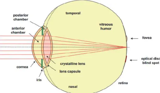
SinceDRis a pathology that affects vision, some aspects about the eye’s anatomy must
be taken in account, namely the structures that constitute this organ. The human visual system, as well as other vertebrates is constituted by three major components that work together, the eyes, that capture light and turn it into stimulus that are transmitted to the brain and processed by it, the visual path, that modifies and transmits those stimulus since they are received by the eye until they reach the brain, and finally, the visual centers of the brain, that interpret the information received so that they can form a reaction to it [4].
Vision works based on the reflection and absorption of light, when it interacts with the surface of an object, providing information about the presence/absence of those, as well as its structure and composition [4].
When light propagates in Air, it has a velocity of 3.0E8 m/s, that represents a refractive index of n=1, as stated by SI Unit Measurement system. This value depends on the medium the light it is propagating in. When entering the eye through the Cornea, a layer with only 0.5mm thickness, its refractive index is n=1.377. Then it reaches the anterior chamber, with a lower refractive index, of n=1.336, and a thickness of 3.04mm, ending at the Iris. This path, causes the light rays to get closer together, as it is seen in Figure2.1
[5].
The Iris regulates the amount of light that enters the eye, since it’s a diaphragm of variable diameter, which controls the numerical aperture and the radiance entering the eye [5].
By then, a lens of variable shape and size changes its refractive power, so that the eye can accommodate to an object a certain distance. Behind the lens, the light passes
C H A P T E R 2 . T H E O R E T I C A L C O N C E P T S
through the vitreous humor and it’s received at the retina where the detection of light takes place.
The Fovea, central area of the retina, is an important structure forDRdetection, since it’s the region where the light is most focused on when the eye is focused on a certain object, therefore it is the portion of the retina that presents the best image detail. This structure is a small gap inside the Macula, that by its end is a 4mm diameter yellow point, next to the center of the posterior retina [6].
It’s through the Optical Disc that the central artery of the retina enters the eye, and the central vein of the retina and the optical nerve exit, providing the connection to the brain. The ramifications of this vessels spread around the surface of the retina. The optical disc does not contain photo-receptor cells, reason why it is known as the blind spot of the eye [6].
Figure 2.1: Fundus photograph of the right eye. It is possible to see the most relevant structures of the retina. Adapted from [5].
The eye has three chambers (Figure 2.1), an anterior small chamber, mentioned before, a posterior chamber and a vitreous chamber. The anterior chamber is located between the cornea and the iris, and the posterior between the iris and the lens. Both of these contain aqueous humor inside, to help maintain the intraocular pressure, which helps maintain the approximately spherical form of the ocular globe [6].
It is normal to use an analogy between the filming camera and the human eye, since both of them are optical structures, with the goal of capturing visual images resulting from the interaction of light (namely through absorption, transmission and reflection) with different materials. Both have a lens system and a variable aperture, which in the eye is the pupil. In the cameras there is the film, where the image is formed, which in the eye corresponds to the retina [6].
2 . 2 . D I A B E T I C R E T I N O PAT H Y
2.2
Diabetic Retinopathy
Diabetes mellitus is a metabolic disease characterized by hyperglycemia, which results from a flaw in the production of insulin and/or its non-actuation, even if it is produced. If this flaw is not controlled, hyperglycemia may lead to the bad functioning of several organs, specially the eyes, kidneys, nerves and blood vessels. In extreme cases it can lead to the total failure of one or more of this organs [7].
Individuals diagnosed with Diabetes mellitus may develop a complication derived from this disease, that is known as Diabetic Retinopathy (DR). This pathology begins for being asymptomatic, that causing it to be the main cause of avoidable blindness in the World [7].
Given the case where a person with diabetes mellitus goes through a long period of hyperglycemia, it’s possible there is an accumulation of fluid inside the ocular lens, that controls the focus of the viewed images.
This liquid accumulation leads to changes in the curvature of the lens, and therefore the vision gets blurred. This symptoms may improve as soon as the glycemia levels are normalized.
There are two known types ofDR, that differ in the way the blood vessels are affected
by diabetes mellitus: [7]
• Proliferative DR - It’s a result of the abnormal growth of new blood vessels in the retina, the optical disc or inside the vitreous cavity. Due to the fragile nature of this new vessels, there is a great probability for them to collapse, originating hemorrhages and/or detaching from the retina, possibly leading to blindness [8].
• Non-proliferativeDR- The deterioration of the blood vessels in the retina is the cause of this type of DR, causing blood shed that can generate microaneurysms, intra-retina hemorrhages and ocular edemas (liquid accumulation inside the eye). Besides blood vessels, there are capillaries in the eye that contain lipids. These can also burst, leading to hard and soft exudates. Non-ProliferativeDRcan be classified according to its severity, thus if there is at least one microaneurysm, it’s classified as mild state. The presence of blood hemorrhages leads to the moderate state and the severe state happens when there is more than 20 hemorrhages in 4 quadrants, vessel distention in 2 quadrants or intraretinal microvascular abnormalities in 1 of the quadrants [7–9]
There are several imaging methods to diagnoseDR. For the purpose of this thesis only the non-invasive ones will be approached, sinceEFSpurpose is insert in this category.
2.3
Fundus Photography
Fundus Photography (FP) is based on the principle of indirect ophthalmoscopy, where a digital camera is set at a certain distance from the eye, that usually varies between 5
C H A P T E R 2 . T H E O R E T I C A L C O N C E P T S
to 50 mm. The camera’s lens has the capacity to, simultaneously, transmit rays of light into the eye and collect the reflected rays, providing an amplified image of the fundus, as illustrated in the top row of Figure 2.2.
SomeFPdevices can be non-mydriatic, which means there is no need to dilate the eye through pharmacological agents. This constitutes a big advantage, since that forced dilation is extremely incommode for the patient undergoing the diagnosis [10].
As described in Section2.2, in Figure2.2B and C, it is possible to observe the fundus of a subject withDR. In this particular case some significant structures, characteristic of
DRcan be seen, such as exudates, due to capillaries rupture that caused lipids leakage, hemorrhages, caused by blood vessels burst, and microaneurysms, with the appearance of small and well-defined red dots. For this last case it’s important to mention that microaneurysms’ size grows according to the stage of the pathology. In early stages these are about 25-125 µm. Given this fact, fundus cameras should have a high resolution, that is needed for an early diagnosis of the pathology. [9].
Figure 2.2: Fundus Photographs obtained from fundus cameras. A represents a healthy fundus. Figures B and C representDRaffected fundus, given the existence of exudates,
hemorrhages and microaneurysms, resultant from the neovascularization described on the images bellow. Adapted from [11].
In order to understand howFP cameras work, a few of its characteristics must be known, being the most important concepts: [12]
• Angular Field of View (AFOV)-Full angle, in degrees, associated with the hori-zontal dimension (width) of the sensor that the lens is to be used with;
• Focal Length, f - Defines the lens’AFOV. It is the calculation of an optical distance from the point where light rays converge to form a sharp image of an object to
2 . 3 . F U N D U S P H O T O G R A P H Y
the digital image sensor. For a given sensor size, the shorter the focal length, the wider theAFOVof the lens. This way, theAFOVcan be calculated according to the equation 2.1, on whichh represents the horizontal dimension of the sensor and f
the focal length, all measured in millimeters.
AFOV (o) = 2xtan−1 h
2f (2.1)
• Spatial Resolution - Defined as the minimum distance between two image pixels, formed by the intersection of a column and a row that form the digital image, in order to distinguish them. Thus the image resolution is given by the number of pixels that form the image obtained [13].
• Image Sensor - Cameras are constituted by image sensors, that process the im-age, considered aspects such as pixel size and distribution, or light sensitivity, as described in section2.4.
• Optics System Quality - Optical Systems forDRassessment include a number of optics materials, such as optical lenses and mirrors, through which rays of light pass. Some of this rays will reach the retina, while others undergo the inverse process, thus providing an image of the human fundus. If the components that constitute this systems are not in perfect condition, or the design isn’t perfectly aligned, optical aberrations will surge, possibly leading to diagnosis errors [3].
Besides the characteristics mentioned, it’s relevant to understand the difference be-tween theAFOVof a camera and theFOVof an image, since it is an important feature of the obtained image of the fundus. TheFOVis influenced by the optical composition of the lens, and it indicates the area of the image (in this case, the retina) that the lens will cover at a certain distance, which means that it indicates the angle through which a device can capture electromagnetic radiation. Because of this aspect, theFOVof a camera it’s usually measured in angles [14].
A FOV of 30º is usually considered the normal angle of visualization, generating a plane fundus image 2.5 times bigger then the real image. There are cameras with
FOV’s between 45º and 60º, however, one must remember that cameras with biggerFOV’s usually require pupil’s with wider diameters [14].
In order for Fundus Photography or Recording Systems to be approved, thus be com-mercialized as a diagnosis support system forDRassessment, the requisites established by
theInternational Standard for Ophthalmic Instruments - Fundus cameras (ISO 10940:2009)
must be fulfilled, since this protocol specifies the necessary requirements and test meth-ods.
The following listed tests are part of the full test list that must be performed for the approval of the optical system as aDRassessment diagnosis, as stated inISO 10940:2009.
C H A P T E R 2 . T H E O R E T I C A L C O N C E P T S
are the only ones refereed to in this thesis. For the complete approval of the system there are a few more tests, namely related to the optical path, that need to be fulfilled [15].
• Check the Resolving power of the fundus camera optics - The test targets images from the center, middle and periphery used for checking resolving power.
• Check the Field-of-View - The check shall be done by taking a picture of a gradu-ated target (i.e. millimeter paper), placed 1 m from the entrance pupil of the fundus camera. The scale has to be perpendicular to the optical axis and centered to the field of view. From the image obtained, the distance 2r can then me measured, in millimeters, from edge to edge on the image of the visible scale. The angular field of view is then found according to the equation:
FOV (o) = 2(arctan( r
1000)) (2.2)
It should also be referred that there are other techniques that also use a camera cou-pled to an image processor, as is the case ofFluorescence Angiography (FA). Due to this reason, FA was used during many years to diagnose pathologies related to the retina, as instanceDR. However, it is being surpassed by theFPtechnique, becauseFAhas the disadvantage of having to rely on an intravenous injection of fluorescent sodium to obtain the fundus image [14].
2.4
Camera Concepts
In order to select a camera to integrate in the EFS prototype, it’s necessary to have a wide background knowledge about the components that constitute this devices, since its components affect the fundus image that constitutes the final outcome of this process.
One of the most important parts of the camera’s optical system is the sensor, that contains millions of pixels for image resolution, and creates the conversion of an analog image into a digital one [16].
It’s the combination between the camera’s sensor, lens and image processor that dic-tates the quality of the image produced, therefore even if two cameras have the exact same sensor, the image obtained can be very different from each other [16].
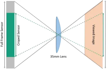
The simplified block diagram in Figure2.4represents the architecture behind cam-era’s functioning. First, the scene is focused on the image sensor, using imaging optics, the group constituted by an optical lens and the image sensor. The focal length of a lens depends, not only on the lens itself, but also on the sensor used, and more specifically on its size.
As represented by the scheme on Figure2.3, for smaller sensor sizes, using the same lens for imaging, the image will appear more cropped, thus theAFOVof a camera with this sensor, will be smaller. This factor can be measured by the crop factor, that is stan-dardized as n=1 for full frame sensors, that provide a film pane of exactly 36 x 24 mm [17].
2 . 4 . C A M E R A C O N C E P T S
Figure 2.3: Schematics of theAFOVrepresentation for two cameras using the same lens and sensors with different sizes.
The incident light is then converted into an array of electrical signals by a two-dimensional array of pixels. Color imaging is done by the use of a color-filtered array. In this specific case, aRed-Green-Blue Color Model (RGB)filter is used. This filter causes each pixel to produce a signal corresponding to only one of these three colors. The analog pixel data (i.e. the electrical signals) are then read out of the image sensor and digitized by an Analog to Digital Converter (ADC)converter, producing a full color image, with green, blue and red values for each pixel in that image, as well as a spatial interpolation operation, known asdemosaicking [18].
After this operations are performed, Image Signal Processors (ISP) functionalities can still be added, for white-balance, auto-focus, auto-exposure and color correction operations, as well as to diminish the adverse effects of fault pixels and imperfect optics. The final step of the process is the image compression and memory storing [18].
C H A P T E R 2 . T H E O R E T I C A L C O N C E P T S
Image sensors consist on arrays of pixels, each containing a photodetector for incident light conversion into photocurrent. Some circuits need to convert that photocurrent into eletric charge to read it. The most common sensors belong to two categories, represented in Figure2.5: [14,18]
• Charged-Coupled Device (CCD)
• Metal Oxide Semi-Conductor (CMOS)
Figure 2.5: Camera sensor types: (a)CCDsensor and (b)CMOSsensor architectures [18].
Invented in 1970,CCDis a silicon sensor, constituted by a series of photosensitive circuits ((a) in Figure2.5), that move the charges inside the sensor. This is a sequential logic circuit, therefore it needs two clocks for set or reset states, simultaneously. The
CCDsensor is an analog device, however, its output is immediately converted in a digital signal through anADC, that exists in digital cameras [14,19].
Before reaching the exit amplifier, the charges must be transferred, and the limited velocity at which this transfer occurs must be taken into consideration, since it leads to delays in the velocity between shoots. Apart from this delay, it’s this charge’s transfer that causes a bigger sensitivity and pixel-to-pixel consistency, that characterizes theCCD
sensors [14].
The main advantages of using a CCD sensor are the higher quality of the images obtained (especially in low light environments), given there is less noise, better depth of color (twice the dynamic range achieved byCMOSsensors), higher resolution and greater sensitivity to light [20].
CMOSsensors are digital sensors, constituted by an integrated circuit that converts the photosensitive pixel’s charge into voltage on each smaller circuit that composes it. After this conversion,CMOSpossesses a multiplex system by line and column that allows
2 . 4 . C A M E R A C O N C E P T S
the several signals obtained to be converted into just one signal, that will be sent to the multipleADCconverters presents in the camera chip ( Figure2.5-b) [19].
Each smaller circuit is composed by one photodiode and three transistors. The sensor has the reset or pixel activation function, as well as the amplify/convert the charge into analog signal, and select or synthesize the information of the several signals in a single one. Therefore, the velocity of the CMOS sensors is far greater then theCCD sensors, however, the sensibility is way smaller, and the noise that contaminate the image is bigger, what is due to the inconsistency on the several charge to voltage conversion circuits [19].
TheCMOSadvantages, when compared toCCDare: [19,20].
• Lower costs, due to a lower flux of charges, or current in theCMOSsensor.
• Its ability to work with very high luminosity levels, what allows its use on dynamic reach cameras.
• Allowing the integration of stabilization systems, image treatment and compression.
• Fastest image processing. CMOS sensors are constituted by active pixels and an
ADCconverter on the same chip.
• Low power consumption, due to 100 times less flow of charge, when compared to
CCD.
When looking for a camera to integrate with theEFS prototype, it was relevant to check for cameras withoutInfra Red (IR)filters, since these record short-waveIR frequen-cies, constituting a good feature forEFS, given the capturing is done under this low-light environment conditions.
C
h
a
p
t
e
r
3
L i t e r a t u r e R e v i e w
Fundus imaging may be obtained by several devices. The first device for fundus viewing was the ophthalmoscope, a small, handled device that didn’t allowDRscreening, given it’s lowFOV. The growing integration of technology in imaging techniques lead to the appearance of Non-mydriatic Cameras, that are an efficientDRscreening technique, but aren’t portable and are very expensive. To suppress this limitations,FPsystems are now starting to be available in the market [21,22].
3.1
Non-mydriatic Automated Cameras
Non-mydriatic cameras, as seen in Figure 3.1, do not require pupil dilation by the use of mydriatic agents, allowing the user to see the fundus on a digital screen, with the possibility to zoom in, perform vessel and/or lesion measurements and share those images with the patients and onPicture Archiving and Communication System (PACS)systems [22].
C H A P T E R 3 . L I T E R AT U R E R E V I E W
Stereoscopic color fundus photography in 7 standard fields, and with a 30ºFOV, is, as defined by Early Treatment Diabetic Retinopathy Study group, the Gold Standard forDR
assessment in the world. Table-top fundus cameras are included in this group, being the most commonly used devices by Portuguese ophthalmologists forDRassessment. Despite their good results in terms of diagnosis accuracy, there are two main disadvantages for the use of such devices, namely the costs associated with purchase and their very low portability, since they are required to be placed on a fixed, plain surface in order to be used, therefore it becomes very difficult to transport such devices into rural areas, where the access to medical devices is a challenge [23].
3.2
Handheld Fundus Cameras
As described in Subsection 2.3, FP has been a very interesting area for engineers and developers to explore. Since Carl Zeiss, in 1926, created a 10º FOV, flash powder and color film equipped mydriatic fundus camera,FPhas improved a lot. Some of the most relevant innovations are related to the appearance of nonmydriactic imaging, electronic illumination control, automated eye alignment, and high resolution digital image capture. The combination of this new features madeFPa standard technique for developing and documenting retinal disease, such asDR[24].
Despite this improvements, fundus cameras still don’t take full advantage of consumer camera’s built-in function and space saving. Besides that, the prices of such cameras are still too high, specially for underdeveloped countries, that still face a great lack of diagnosis resources, andDRdiagnosis is no exception [25].
In order to face this disadvantages, Kenneth Tran developed a study with the main goal of creating aFPdevice for the capture of human fundus images and the documenta-tion of retinal pathologies, using only components under £1000. A front objective lens, positioned at 5 to 50 mm from the front of the eye was used. The purpose of this lens was to simultaneously relay light rays towards the eye and collect the reflected light, providing a view of the fundus. The camera used was Panasonic’s Lumix G2 [26].
To allow a better comparison between this camera and theEFScameras, the following characteristics of the Lumix G2 should be evaluated: [26]
• CMOSsensor
• Rapid Automatic Focus
• Exposure Capabilities
• Live-view imaging
• 12 MP resolution
3 . 3 . O P T O M E D AU R O R A
To increase the focusing ability, there was the need to attach a screw-in macro lens to the front lens of the Panasonic Lumix G2. The autofocus, as well as the image composition, are both performed on the camera’s built-in LCD screen. The best way to obtain the desired focus is to move the focusing area of the camera over the optic nerve , since the contrast between the surrounding vasculature and the optic disc allows the camera’s contrast-based autofocusing algorithms to lock the accurate focus. This way, a fundus image is acquired by following a point-and-shoot operation sequence [26].
Figure 3.2: Hand-held, low cost fundus camera prototype developed in [26].
The final fundus camera prototype developed (Figure 3.5) was able to be used in a handheld portable manner, with the subject sitting down in a reclined head position. The camera should be operated with both hands, while the user was standing. In most cases, the camera was used 40 to 45 mm away from the subject’s eye, depending upon variances in refractive power. Both the optic nerves and macula-centered images could be obtained with the device, but only with a certain degree of subject cooperation [26].
Each image acquisition lasted 10 to 25 seconds, but this parameter, as well as image quality, depended greatly on the dilation pupil size and the reflectivity of the fundus, resulting in low, partial or vingnette exposure of the fundus. In an attempt to fix this situation, it was stated by the investigators that the user should take two to three fundus photographs to ensure satisfactory image quality for clinical diagnosis. Overall, 22 of 26 photos (85 %) taken were judged sufficient for clinical diagnosis.
Despite all this, the biggest disadvantage of the prototype created by Tran, in [26] is the need for pharmacological mydriasis, that as stated before, causes a great discomfort to subjects.
3.3
Optomed Aurora
Aurora fundus camera, developed by Optomed, is a non-mydriatic imaging system for
DRdetection, Figure3.3. Its main features include: [27]
C H A P T E R 3 . L I T E R AT U R E R E V I E W
• Compact and portable for clinics of all sizes.
• Rechargeable battery, including an Optomed dual charger for power supply.
• Image archive including Digital Imaging and Communications in Medicine (DI-COM)systems.
• Minimum 3.1mm pupil size.
• 5MP camera resolution.
• 9 internal fixation targets for peripheral imaging.
• Color, red-free,IRand Low-red photography.
Figure 3.3: Optomed Aurora fundus camera [27].
3.4
OICO Fundus Camera
OICO Fundus Camera is a portable, automated, non-mydriatic camera, that can also be used on manual mode, Figure3.4.
The most relevant features of this camera are: [28]
• 30º to 35ºFOV, depending on pupil size.
• Pupil must be at least 3.5mm, without dilation.
• Build-in camera with 12MP resolution.
• 4h Battery autonomy. Buying the system also includes its own charger.
• White-light flash for fundus illumination andIRlight for system adjustment.
3 . 5 . V O L K P I C T O R P LU S
• Bluetooth and WiFi system, to facilitate the information share with dropbox, Google, Microsoft or other sharing systems. Medical systems such asDICOMandPACSare also available.
Figure 3.4: OICO fundus camera [28].
This camera still has improvement points to consider, being the most relevant ones the need for diopetry compensation, that has to be inserted manually by the doctor and it doesn’t possess internal fixation targets.
3.5
Volk Pictor Plus
Volk Pictor Plus is an ophtalmological device, non-mydriatic, portable and relatively light. This features make this device easy to use for examinations outside the hospital, reaching a greater number of patients.
The main characteristics of Volk Pictor Plus are: [29]
• Non-mydriatic.
• 5 MP Image sensor.
• 40º staticFOV.
• 120º dynamicFOV.
• Two illumination modules: white-light,IRLEDs.
• Image transfer throughUniversal Serial Bus (USB)port or via WiFi network.
• AutoFocus and Automatic Shooting.
C H A P T E R 3 . L I T E R AT U R E R E V I E W
• Eight internal Fixation Targets.
• Pupil minimum size of 2.7 mm without pupil dilation.
Figure 3.5: Volk Pictor Plus fundus camera. Adapted from [29].
3.6
EyeFundusScope
The current prototype developed by Fraunhofer, consists in a mobile device that can illuminate the human fundus and capture images of it through a smartphone camera, as it is seen in Figure3.6.
The main features of theEFSprototype are: [3]
• Handheld device.
• Low-cost.
• Non-mydriatic.
• 40ºFOV.
• Image capture with Nexus 5X smartphone camera.
• 4mm Pupil Size.
As it happens with OICO Fundus Camera (Section3.4),EFSdoesn’t integrate internal fixation targets. This aspect, as well as the integration of an internal, fixed camera on the prototype, are two important improvements, that are part of the objectives of the current work.
3 . 7 . F U N D U S P H O T O G R A P H Y C A M E R A S C O M PA R I S O N
Figure 3.6: EyeFundusScope mechanical prototype schematics. Schematics developed with SolidWorks in [3].
3.7
Fundus Photography Cameras Comparison
In tables 3.1and 3.2, it is possible to compare some relevant characteristics of Fundus Photography devices available in the market, namely the ones mentioned in Subsections
3.3,3.4,3.5, in order to establish a correlation to the solution presented by Fraunhofer’s
EFS, described in Subsection3.6.
Table 3.1: Fundus Photography Devices. [28–33]
D-Eye
Ophtalmoscope VOLK InView VOLK Pictor Plus
Horus DEC 200 OICO Fundus Camera Optomed Smartscope pro FOV 20º (Mydriasis) 6º (No Mydriasis) 50º (Static) 80º (Dynamic) 40º(Static) 120º(Dynamic) 45º 30-35º 40º Resolution (MP) 1 1 5 5 12 5 Pupil Dilation Yes Yes (5mm pupil minimum) No (3mm pupil minimum) No No (3.5mm pupil minimum) No (3.5mm pupil minimum) Internal Fixation Targets No No 9 7 No 9
C H A P T E R 3 . L I T E R AT U R E R E V I E W
Table 3.2: Fundus Photography Devices. [3,27,34–36]
Optomed Aurora Zeiss
VISUSCOUT 100 Eyenez V300 EpiCam C EyeFundusScope FOV 50º 40º (Static) 45º 33º(Vertical) 45º
(Horizontal) 40º Resolution (MP) 5 5 5 1.3 (USB 2.0) and
5 (USB 3.0)
12 (using Nexus 5X smartphone) Pupil Dilation No (3.1mm pupil
minimum) No (3.5mm pupil minimum) No No (4mm pupil minimum) No (4mm pupil minimum) Internal Fixation Targets 9 9 No No No
The analysis of Tables 3.1 and 3.2 allowed to the comparison of some aspects of available fundus cameras and the currentEFSprototype.
TheFOVof fundus cameras, as referred inISO 10940:2009 [15] refers to the the area of the fundus that can be imaged by this devices in single field fundus images and it has to be big enough to capture the optic nerve and the macula, always keeping a compromise with image resolution.EFShas a 40ºFOV, this value has a good range for capturing this structures, despite other devices, like Aurora fundus camera, have biggerFOVvalues.
Despite this, single field fundus images are not always enough to reach an accurate diagnosis forDR, considering that a significant proportion of the fundus remains un-covered [25]. This factor can be compensated by adding Internal or External fixation points to the fundus camera, since these provide a fixed target for the patient to fixate, in different positions, that are acquired and then stitched in a wider fundus image, as will be discussed in Subsection4.2.2.
As described on Table 3.2, EFS doesn’t have internal fixation targets at this point, which is a great disadvantage when in comparison to the other devices mentioned. Thus, given this feature’s importance for the system differentiation, it constituted one of the main improvement points that is a part of the objectives in the current work.
EFSis a non-mydriatic camera, which is a strong advantage in comparison to others that do not have this feature, like D-Eye Ophthalmoscope and VOLK InView fundus cam-era. This feature reduces patient discomfort related to pupil dilation via pharmacological substances, and eases the image acquisition for the specialized technician handling the device.
For the image acquisition, a light source is needed, since the fundus is not illuminated as is. This way,EFSuses a flash to capture the final fundus image. Another option, also studied in the beginning of this work, was the use of a camera without IRfilters. This feature, enables this cameras to display low-light environment scenarios. Raspberry Pi NoIR Camera is included in this category, therefore being considered one of the solutions to integrate in the FOV prototype. Nonetheless, the use of a Raspberry Pi Computer Board would not be the best option in terms of prototyping, causing design issues and requiring additional programming.
Another consideration toEFS, that increases its commodity to the patient undergoing the examination, is the integrated illumination module. This module, also known as
3 . 8 . F R AU N H O F E R E N H A N C E D C A M E R A A P I
Light Control, provides the user control over the light intensity, so that the light incising on the patient’s eye is by one side, enough to illuminate the fundus for image acquisition, and at the same time isn’t too intense that causes pain to that same patient.
3.8
Fraunhofer Enhanced Camera API
TheEFSAndroid application uses Fraunhofer EnhancedCameraAPI library, which is a solution developed for providing a large range of parameters, as is the case of focus, exposure, white balance, digital zoom, preview and acquisition sizes, amongst others.
The main features of this library are:
• Easy configuration of Camera in Android
• Fault tolerant setup of parameters
– Handle multiple possible options
– Ensure that unsupported parameters are not chosen
• Low Level Control over all available parameters
• Access to individual preview frames
Retinal imaging requires very specific parameters. For the illumination of the retina, a warm white LED is needed, thus the white balance should be set to Incandescent.
Two different operation modes are also required, the alignment and acquisition mode. For the first one, since the LED intensity is low, the ISO value must be extremely high and the shutter time needs to be longer as well.
For the acquisition mode, the LED intensity is set to high, therefore the ISO value decreases and the shutter time is shorter (1/20s). More than fifteen Android smartphone’s have been tested and are fully compliant with the EnhancedCameraAPI.
The controllable camera parameters released by Fraunhofer’s EnhancedCameraAPI are a strong feature of this application, given the reasons presented for the importance of such control in the acquisition of fundus images forDRassessment.
Nonetheless, this API still doesn’t provide a solution for the optical alignment issues and image quality if the EFS prototype isn’t used with a specific smartphone, in this case the Nexus 5X smartphone, that was used for the calibration of the optical system. Besides, internal fixation target actuators cannot be controlled with this API. Therefore, this work aims to present a possible solution to improve this points, by trying to keep a set of controllable parameters as the ones controlled by the EnhancedCameraAPI.
C
h
a
p
t
e
r
4
P r o p o s e d A p p r o a c h
4.1
EyeFundusScope Camera Selection
The growing use of smartphones in the daily lives of the great majority of the population changed the way medical devices work today. Smartphone based imaging systems became a reality, that is relatively easy to use and to access. AsEFSaims to reach population that cannot access aDRdiagnosis so easily, or at all, it was first designed to use the smartphone, and therefore its camera, to photograph the ocular fundus.
Smartphone’s compact cameras are the result of the development ofCMOScamera sensors, that made the integration of high pixel camera lens in mobile phones possible, given their very reduced size. The FOV of mobile cameras is usually in the interval of 70º to 80º, which are large values for this characteristic [37]. This kind of cameras have very specific characteristics, that often change between manufacturers, which raises some concerns like the perfectly aligned optical system or the fundus image quality. Concerning this, the selection of a fundus camera for integration in theEFSprototype is extremely important.
CMOSsensors were chosen during the selection of a camera forEFSconsidering their characteristics, as described in Section2.4:
• Lower costs, when compared toCCDsensors.
• Faster image processing, relevant for a video stream of the fundus image without delays.
• Low power consumption, important given the power source of the entire system will be the smartphone’s battery.
• Reduced size, for enabling the future integration inside theEFS prototype, that aims to be a handheld device.
C H A P T E R 4 . P R O P O S E D A P P R OAC H
TheEFS cameras studied include three relevant camera types: Embedded Camera Modules, Dedicated Camera Boards andUVC-Compliant Cameras.
These cameras have some characteristics in common, such as the available image sensor interface, that is usually of the parallel or MIPI type. Parallel interfaces use more than one wire to establish the communication between systems, which makes it possible for both spatial and temporal dimensions to be available for the data.
MIPI interface, namely MIPI’s CSI-2 interface, is a low-power, high-speed and robust hardware interface that implements camera and imaging components in mobile devices [38].
Despite these similarities, the camera types mentioned are different in many aspects. Camera modules consist on cameras that can apply a certain level of post capture pro-cessing to the images captured. In order to make its use simpler to the developer, camera modules have built-in sensor interfaces, so that there is no need to alter the driver used to communicate with the board attached, since all camera sensors, even future ones, are supported by the camera driver supplied by the manufacturers.
Dedicated camera boards are the central module of embedded image capturing sys-tems, Figure4.1. They’re composed by a processing chip, memory disc, power supply source and some may include ethernet,USBand/or HDMI ports. Raspberry Pi NoIR V2 camera board is an open design camera board, and it was initially studied for integration in the prototype. This camera seemed like a good option because of it’s characteristics, namely its high flexibility and operational simplicity, at the cost of requiring a relatively cumbersome Raspberry Pi 1,2 or 3 computer board [39,40].
Figure 4.1: Raspberry Pi NoIR Camera Board used in [41], for the development of an inexpensive fundus camera.
Raspberry Pi NoIR V2 camera is constituted by an image sensor with 8MP image resolution, but the feature that makes this camera the most appealing forEFSintegration is that it doesn’t have IRfilters. Without these, the camera is capable of capturing IR
4 . 1 . E Y E F U N D U S S C O P E C A M E R A S E L E C T I O N
With this feature, it becomes possible to capture fundus images without an illumina-tion module. This is an important feature, since the prolonged use of a light source to illuminate the retina can damage it [40,41].
But despite the clear advantages presented by Raspberry’s NoIR Camera, there were four disadvantages that lead to the discard of this option forEFSintegration. The first one is that there already was a solution forDRassessment based on this camera module, therefore the current approach wouldn’t have a great differentiation from the current literature [41].
The second reason is that in terms of prototyping, it’s not as advantageous to have a Raspberry Pi Computer Board in the final solution, given the space it occupies, that would require many changes to the current design.
Besides the solution would only be available for the integration of Raspberry Pi Com-puter Board based cameras. This would limit the solution developed, making it com-pletely focused on a specific camera board device, thus making the solution less embrac-ing for future cameras, with faster and better quality sensors.
The fourth reason, and the most decisive one, was that Raspberry Pi requires an external power supply. This would be a major limitation to the system’s portability, since this pretends to use only the smartphone’s battery as the power supply for the entire system.
Embedded camera modules are very versatile and have a wide range of options, since they can be interfaced to a specific processor, of the developers choice, or to a lens of their choice. This type of camera modules arePlug & Play devices, that in opposite to Dedicated
Camera Boards, don’t require a specific programmable Board to be connected to a device, in this case, the smartphone. For the desired solution, ae-con Systems embedded camera,
alsoUVC-Compliant, Figure4.2was evaluated as a possibility forEFSintegration, given it is a Near Infra Red (NIR) camera with a 60ºAFOV value, that is within the desired range forEFSintegration, and it’s low price of $89. But still, given delays in the delivery of the embedded system from it’s manufacturer, this option wasn’t possible to integrate during the course of this thesis [42,43].
Figure 4.2: Embedded e-CAM51_USB - 5 MP OEM USB Camera Module [43].
Finally, the last option to be considered is the use ofUVC-Compliant Cameras, that are natively supported by mostOperative System (OS).UVC-Compliant Cameras, commonly known asPlug & Play cameras, are easily plugged in Windows and Linux systems, without
C H A P T E R 4 . P R O P O S E D A P P R OAC H
Cameras haveUSB2.0 or 3.0 interfaces, allowing the connection to otherUSBcompliant devices, as is the case of the smartphone used in this thesis.
UVC-Compliant Cameras are equipped withUVCcontrols to adjust imaging parame-ters, such as brightness, contrast, hue, saturation, sharpness, black-light, gamma, white balance, exposure, gain and focus. Ascella (See3CAM_CX3ISPRDK) and Logitech C270 webcamera in Figure4.3were the twoUVC-Compliant cameras selected for this category, as will be discussed in Subsection4.2.1[44].
a UVC-Compliant Cam-era Module - Ascella (See3CAM_CX3ISPRDK).
b Logitech C270 webcamera
UVC-Compliant.
Figure 4.3: Logitech C270 and Ascella (See3CAM_CX3ISPRDK) UVC-Compliant Cam-eras [44,45]
In order to select the final camera for prototype integration, an important character-istic of the camera types discussed, that had to be considered was their interface. There are two relevantUSBinterfaces, 2.0 and 3.0, with important variations from one another that affect, amongst other characteristics, the speed of the data transfer between devices. A more detailed analysis of this interfaces is done in Subsection4.1.1. This is relevant for this work, since the aim is to get a connection between theUVC-Compliant Cameras and the Android smartphone, with enough speed to allow the simultaneous display and capture of the fundus image, with the lowest delay possible.
4.1.1 Universal Serial Bus (USB) Specification
USBis a personal-computer interface, established in the majority of devices, such as key-boards, computers, cameras, drives, audio and video devices, amongst others. This is a versatile technology, that primes for being very reliable, inexpensive and most impor-tantly for being supported by mostOS.
The mentioned characteristics makeUSBa likely solution for enabling the commu-nication between a computer to a device, or as is the case of this work, a camera and a smartphone.
USB has had many improvements, one of which being the data transfer speed im-provement, known as SuperSpeed USB (SS)and a more flexible power delivery. These features are the main distinction betweenUSB2.0 and 3.0 interfaces.
4 . 1 . E Y E F U N D U S S C O P E C A M E R A S E L E C T I O N
USB2.0 showed that a bus 40 times faster then the previous versions, could still sup-port both low and high speed interfaces. The ability to use several speed levels increased the complexity of the serial hubs, but managed to conserve bandwidth so that the hubs used could remain the same for both interfaces. What causes this difference in terms of data transfer speed isUSB3.0 largerBand Width (BW), causing great improvements in transfer rate, with a maximum of 400 MByte/s. This is possible due to the mass data transfer mechanism that is characteristic of theUSBinterface [46].
USB3.0 interface is compatible withUSB2.0 and 3.0 hosts and hubs supporting all four speeds. This new interface was created to complementUSB2.0 specifications [46].
In conclusion, the main add-on to theUSB2.0, was the speed increase.USB3.0 is 10 times faster thenUSB2.0, plus it can carry data on both directions at the same time, thus constituting a more efficient solution [46].
In the specific case of Android smartphones, theUSBinterface is usually micro-USB, and it can be of several types. The most common is the micro-USBType-B port [47].
The newest smartphone devices are equipped with USB Type-C port. This is an improvement in terms of data-transfer speed and power saving, and as it happens with the mentionedUSB 3.0/3.1, micro-USBType-C is much more simple then its previous Type-B version. USB Type-C ports have a range of 15 – 100 Watts per port, featuring
support for theUSBpower delivery specification. This means that a smartphone with a
USBType-C entrance can easily charge other devices (apart from a full desktop PC). If we’re referring to a micro-USBType-B port, it ts limited to a maximum of 7.5 Watts [47].
As the purpose of this thesis includes the connection between an external camera, with anUSB2.0 or 3.0 interface and an Android smartphone with a micro- port, that will act as the host device, providing the power to support the entire system created, then an
USB On-The-Go (OTG)cable must be used to fit this purpose [48].
Given this information onUSBInterfaces, the best options in terms of data-transfer speed, so that the Android Application developed is as fast as possible in terms of simul-taneously displaying a stream image from the camera selected forEFS, and allow image capturing is a smartphone with a micro-USBType-C port and with a camera withUSB
3.0 interface.
Despite this fact, the smartphone available for testing during this thesis was a Sam-sung A3 2016, with a micro-USBType-B interface, that could only be connected toUSB
2.0 compliant camera devices. Nonetheless, the application proved to be fast enough to fulfill the requirements established above, meaning that if a device withUSB3.0 interface and micro-USBType-C is used instead of the Samsung A3 2016, the results are expected to be even better then the ones obtained.
This proves that, despiteUSB3.0 interface is faster then its previousUSB2.0 version, the use of a camera with aUSB3.0 connection is not required for the good functioning of the CameraApp developed in this work.
C H A P T E R 4 . P R O P O S E D A P P R OAC H
4.2
CameraApp: Android Camera Application Development
One of the main Objectives of the present thesis is to establish a communication protocol to allow the Android smartphone to control the camera, simultaneously to the capture of fundus images by the user.As it was mentioned in Section4.1,UVC-Compliant Cameras are the most relevant cameras forEFSintegration. This way, theUSBVideo Class Protocol must be studied to allow such connection.
This way, an Android Camera Application constitutes the approach developed in the thesis, allowing the communication between Android,UVC-Compliant Cameras and an ATMega2560 board, that will add an extra, and very important feature in the detection ofDR, Internal Fixation Target Actuators, further discussed in this Chapter’s Subsection
4.2.2.
4.2.1 USB Video Class Protocol
After a careful research of the potential camera types, in Section4.1, and the type ofUSB
Interfaces available, in Subsection4.1.1,UVC-Compliant Cameras were selected as the best option to integrate in theEFSprototype. It is very important to know how to make the connection between the camera and the smartphone, in a way that the communication protocol selected in this thesis, can adapt to a wide range ofUVC-Compatible devices.
Considering,UVCdrivers must be evaluated, since they seem to be a good option for the solution this thesis aims to achieve.
UVCis a Microsoft-provided AVStream minidriver that provides driver support for
USBVideo Class Compliant Devices. This means that when a device usesUVC, there is no need to develop a new, specific driver for it, since the device will work automatically with the system-supplied driver. This protocol enables devices like webcameras, digital camcorders, analog video converters, analog and digital television tuners, amongst others, to connect seamlessly with host machines. UVCsupports streaming from multiple video formats, that includeMotion JPEG (MJPEG)for instance. [49].
ManyOSplatforms already have native support forUVCdrivers, which greatly re-duces the time required for developers to createUSBvideo devices.
This way, by usingUVC models, it is possible to implement video streaming hard-ware according to the guidelines in the USB Device class definition for video devices specification, and without having to create proprietary drivers. Besides, there is also the possibility to add vendor-specific processing to theUVCdriver functionality [49].
To make sure the right smartphone-camera connection is chosen, it’s important to know the main advantages of using anUVCdriver:
• No need for development of proprietary drivers.
4 . 2 . C A M E R A A P P : A N D R O I D C A M E R A A P P L I C AT I O N D E V E L O P M E N T
• No maintenance cost.
• Compliant with Selective Suspend power management.
TheUSB Video Class protocol is provided byUSBImplementers Forum, Inc., and it
is a specification for devices that follow Universal Serial Bus technology. This protocol describes the minimum capabilities and characteristics that a video streaming device must support to comply with theUVCspecification.
Devices that follow this protocol have standardized video streaming functionality, and it provides information for designers to builtUVCCompliant Devices, incorporating the video streaming functionality. A number of mandatory or optional requirements are specified, in order to help developers understand how to use theUVCprotocol. [49].
TheUVCprotocol establishes a Video Interface class that groups all functions that can interact withUSB-Compliant Video Data streams. The Video Interface is divided into subclasses, Video Control and Video Streaming Interfaces, that are used for Streaming the Video from theUVCCamera [49].
The video function is constituted by Units, that provide the basic building blocks to fully describe most video functions, and Terminals, divided in Input Terminal (IT), representing a starting point for data stream inside the video function, andOutput Termi-nal (OT), representing an ending-point for output streams. The protocol also allows the user to make some changes to the video being displayed during the stream. For instance, Brightness, White Balance, Gamma, Contrast Controls, amongst others, can be added inside aProcessing Unit (PU), by issuing appropriate requests. This way, these controls can be displayed in a User Inteface (UI)thus providing those features to be controlled [49].
Besides the mentioned terminals, that control image parameters, the UVC protocol also allows the control of some of mechanical (or equivalent digital) features of the device, known asCamera Terminal (CT)controls. These can be features like Auto-Focus, Focus and Auto-Exposure [49].
There is also the possibility for Still Image Capture, associated with the video stream, that can be done by three different methods. The one used in this thesis extracts the next available video frame from the active video pipe in the relevant Video Streaming interface upon receiving the triggered event. This way, the video stream will not be altered or interrupted, and the still image captured will have the same size as the video frames being streamed [49].
CameraApp was build using Android Studio, an Android application development environment. For the development of the application,Java Native Interface (JNI)libraries, that include theUVC-Protocol described, were imported into the code developed in this thesis, for full support forUVC-Compliant Cameras, as well as to provide some of the low-level control for this cameras [50]. ThisJNIlibraries define the way the managed code interacts with native C/C++ code, provided by AndroidNative Development Kit

![Figure 2.5: Camera sensor types: (a) CCD sensor and (b) CMOS sensor architectures [18].](https://thumb-eu.123doks.com/thumbv2/123dok_br/19235590.969448/32.892.162.731.372.681/figure-camera-sensor-types-sensor-cmos-sensor-architectures.webp)
![Figure 3.1: Non-mydriatic Automated Camera used for fundus examination [22].](https://thumb-eu.123doks.com/thumbv2/123dok_br/19235590.969448/35.892.298.598.907.1114/figure-non-mydriatic-automated-camera-used-fundus-examination.webp)
![Figure 3.2: Hand-held, low cost fundus camera prototype developed in [26].](https://thumb-eu.123doks.com/thumbv2/123dok_br/19235590.969448/37.892.276.618.340.549/figure-hand-held-cost-fundus-camera-prototype-developed.webp)
![Figure 3.4: OICO fundus camera [28].](https://thumb-eu.123doks.com/thumbv2/123dok_br/19235590.969448/39.892.294.597.251.549/figure-oico-fundus-camera.webp)
![Figure 3.5: Volk Pictor Plus fundus camera. Adapted from [29].](https://thumb-eu.123doks.com/thumbv2/123dok_br/19235590.969448/40.892.312.587.271.570/figure-volk-pictor-plus-fundus-camera-adapted-from.webp)
![Figure 3.6: EyeFundusScope mechanical prototype schematics. Schematics developed with SolidWorks in [3].](https://thumb-eu.123doks.com/thumbv2/123dok_br/19235590.969448/41.892.295.604.189.559/figure-eyefundusscope-mechanical-prototype-schematics-schematics-developed-solidworks.webp)
![Table 3.2: Fundus Photography Devices. [3, 27, 34–36]](https://thumb-eu.123doks.com/thumbv2/123dok_br/19235590.969448/42.892.127.769.188.336/table-fundus-photography-devices.webp)
