David Simões de Melo
Bachelor Degree in Engineering SciencesOptical Design of a Retinal Image Acquisition
Device for Mobile Diabetic Retinopathy
Assessment
Dissertation submitted in partial fulfillment of the requirements for the degree of
Master of Science in
Biomedical Engineering
Adviser: Pedro Manuel Cardoso Vieira, Professor, NOVA University of Lisbon
Co-adviser: Filipe Soares, PhD, Fraunhofer Portugal AICOS
Examination Committee
Chairperson: Carla Quintão, Professor, NOVA University of Lisbon Members: Paulo Ribeiro, Professor, NOVA University of Lisbon
Optical Design of a Retinal Image Acquisition Device for Mobile Diabetic Retinopathy Assessment
Copyright © David Simões de Melo, Faculty of Sciences and Technology, NOVA University of Lisbon.
The Faculty of Sciences and Technology and the NOVA University of Lisbon have the right, perpetual and without geographical boundaries, to file and publish this dissertation through printed copies reproduced on paper or on digital form, or by any other means known or that may be invented, and to disseminate through scientific repositories and admit its copying and distribution for non-commercial, educational or research purposes, as long as credit is given to the author and editor.
This document was created using the (pdf)LATEX processor, based in the “novathesis” template[1], developed at the Dep. Informática of FCT-NOVA [2].
A c k n o w l e d g e m e n t s
The realization of this master thesis have counted with the support of the Fraunhofer Portugal AICOS institution, giving me all the tools needed for the development of a con-tinuously challenging work. More specifically, I want to thank all the persons responsible for the ScreeningEFSOptics that guide me through all the company procedures, individu-ally João Costa, for his continuous availability and important inputs week after week and Filipe Soares for his always helpful hints.
I would also like to thank the Lisbon office team. Without their continuous good mood and inputs, the realization of this thesis wouldn’t have been so much cheerful.
I would also like to thank my Adviser Professor Pedro Vieira from FCT NOVA for making me always look for the positive side of any problem that appeared, for providing with all the necessary inputs and for steering me in the right direction to overcome any of the challenges I was put to proof.
For my family, high school and college friends, I want to thank them for granting me with their beneficial company, availability and for their valorous inputs during all the academic tests I was put up to.
Finally, I must express my very profound gratitude to my parents for providing me with unfailing support and continuous encouragement throughout my years of study and through the process of researching and writing this thesis. This accomplishment, as all the others I’ve ever achieved would not have been possible without such extraordinary role models to follow.
A b s t r a c t
Diabetes mellitus is a condition that lead to various systemic alterations. These changes, taking place in the blood vessels cause a progressive capillary occlusion and, in the poste-rior eye region, provoke leakages from the vessels to the retina leading to a disease called diabetic retinopathy. This pathology ultimately can lead to complete vision loss, which is an aspect that emphasizes the relevance of the work developed in this thesis.
The initial progression is asymptomatic, so only in advanced and frequently irre-versible stages, the patient becomes aware of the disease. For this reason, a regular follow-up accomplished by eye fundus examination should be performed. Even though, for logistic motivations (lack of equipment, absence of ophthalmology specialists...) the progression-study and diagnose of the disease is often neglected.
To encourage high coverage screening, a compact optical system was designed for a handheld and smartphone-based fundus camera prototype. The key features for the optical system are the low-cost achieved through a simple lens system and a mobile and non-mydriatic acquisition of fundus images with high field-of-view, by a smartphone camera.
The simplicity of the optical system was accomplished by a three lens system setup. The results reveal a system with only a few aberrations in the periphery but with a good resolution at the center of a 41° field-of-view.
Besides the optical system, a mechanical prototype was designed with the purpose of being 3D printed and easily portable.
Also, a light hazard testing procedure was established and applied on a previously developed prototype.
In the future, the implementation of the optical system in the prototype is intended, in order to confirm the applicability of the design in diminishing the burden of screening actions and consequently, empower the early treatment of the pathology.
R e s u m o
A diabetes mellitus é uma condição que leva a várias alterações sistêmicas. Essas altera-ções, ocorrendo nos vasos sanguíneos, causam uma oclusão capilar progressiva que, na região posterior do olho, leva a uma doença chamada retinopatia diabética. Esta patologia, em última instância, pode levar a uma perda completa da visão, o que é um aspeto que enfatiza a relevância do trabalho desenvolvido durante esta tese.
A progressão inicial é assintomática, portanto, apenas em estágios avançados e fre-quentemente irreversíveis, o paciente toma conhecimento da doença. Por este motivo, um acompanhamento regular com realização de exame do fundo ocular deve ser realizado. No entanto, por várias motivações (falta de equipamento, ausência de oftalmologistas...), o estudo da progressão e o diagnóstico da doença são muitas vezes negligenciados.
Para incentivar o rastreio de alta cobertura, um sistema ótico compacto foi projetado para um protótipo de um retinógrafo portátil acoplado a um smartphone. As características-chave do sistema ótico são o baixo custo alcançado através de um sistema de lentes sim-ples e a aquisição móvel e não-midriática de imagens do fundo com alto campo de visão, através da câmara de um smartphone.
A simplicidade do sistema ótico foi conseguida através duma configuração de três lentes. Os resultados revelam um sistema com uma boa resolução central e com 41° de campo de visão na retina.
Para além do sistema ótico, foi projetado um protótipo mecânico com o objetivo de ser impresso em 3D.
Um plano de testes de perigo ocular foi também estabelecido e aplicado num protótipo previamente desenvolvido.
No futuro, pretende-se a implementação do sistema ótico no protótipo, com o objetivo de confirmar a aplicabilidade do projeto na diminuição do peso das ações de rastreio e, consequentemente, possibilitar o tratamento precoce da doença.
C o n t e n t s
Contents xi
List of Figures xv
List of Tables xix
Acronyms xxi
1 Introduction 1
1.1 Context and Motivation . . . 1
1.2 Objectives . . . 2
1.3 Overview . . . 3
2 Diabetic Retinopathy 5 2.1 Pathology Progression . . . 6
2.1.1 Non-Profilerative Diabetic Retinopathy . . . 6
2.1.2 Profilerative Diabetic Retinopathy . . . 8
2.2 Treatment . . . 10
2.3 Diagnosis . . . 10
2.3.1 Fundus Camera . . . 11
2.4 Related Work . . . 12
2.4.1 D-Eye Portable Retinal Imaging System . . . 12
2.4.2 Volk InView - Iphone Fundus Camera . . . 13
2.4.3 Volk Pictor Plus . . . 14
2.4.4 Fraunhofer EyeFundusScope . . . 15
3 Introduction to Optical System Design 17 3.1 Ray Tracing . . . 17
3.2 BEAM IV . . . 18
3.2.1 Optics tables . . . 18
3.2.2 Ray tables . . . 19
3.2.3 Medium tables . . . 20
3.2.4 Helpful BEAM IV Tools . . . 21
3.4 Types of Lenses . . . 23
3.5 Ray tracing models . . . 25
3.5.1 4-Extremes Model . . . 25
3.5.2 Parallel Rays Model . . . 26
3.6 Objective Lens Condition . . . 27
3.7 Fundus Camera Components . . . 28
4 Optical System Design 31 4.1 Previous Optical System . . . 31
4.2 Human Eye Model . . . 33
4.3 Illumination Path . . . 34
4.4 Imaging Path . . . 37
4.5 Imaging Path for Eyes with Refractive Errors . . . 42
4.6 Complete Optical System . . . 44
4.7 Internal Fixation Points . . . 45
5 Mechanical Prototyping 49 6 Light Hazard Measurement 53 6.1 Power Measurements . . . 53
6.1.1 Near Infra-Red LED . . . 55
6.1.2 Visible LED . . . 55
6.1.3 Acquisition Mode . . . 57
6.2 ISO Results . . . 58
6.2.1 Near Infra-Red LED . . . 59
6.2.2 Visible LED . . . 60
6.2.3 Acquisition Mode . . . 61
6.3 ISO Norms Compliance . . . 62
7 Imaging Path Practical Results 65 7.1 Imaging Path Practical Tests for Refractive Errors . . . 70
8 Conclusion 73 8.1 Future Work . . . 74
8.1.1 Optical Components Implementation . . . 74
8.1.2 Light Hazard Measurements on the New Prototype . . . 74
8.1.3 Centralization of all the electronic features . . . 75
9 Publications 77
Bibliography 79
CO N T E N T S
II Field of View calculation 87
III Pulse Width Modulation 91
IV Spectrum and Power Measurements Setups 93
V Spectrometer Output Text File 95
VI Code used for the spectrum analysis 97
VII LED Spectrums 105
L i s t o f F i g u r e s
2.1 Visual differences between an ophthalmological healthy person and a person
with Diabetic Retinopathy. . . 6
2.2 Image of a microaneurysm. . . 7
2.3 Image of an intrarretinal hemorrhage. . . 7
2.4 Image of an exsudate. . . 8
2.5 Neovascularization derived vessels covering the Optical Disk. . . 9
2.6 A Fundus image showing the retina detached from the eye posterior pole. . . 9
2.7 Illustration of the comparison between direct and indirect opthalmoscopy methods. . . 11
2.8 Eye Fundus image where the Blood Vessels, the Macula and the Optic Disk can be seen. . . 11
2.9 Image of the D-EYE Ophthalmoscope coupled to an Iphone. . . 13
2.10 Image of the Volk Inview coupled to an Iphone. . . 14
2.11 Volk Pictor Plus. . . 15
2.12 Image of the previous prototype developed by Fraunhofer Portugal AICOS. . 16
3.1 Computation of an S-LAH64 Aspheric Lens with 30 mmφ. . . 19
3.2 Diagram showing the simulation of the optical system described in Figure 3.1 with the addition of a .RAY Table. . . 20
3.3 Example of the use of Plot 2D with the Random command. . . 21
3.4 Coma explanation. . . 23
3.5 Bi-Convex lens showing too many aberrations. . . 24
3.6 Achromatic lens performance. . . 25
3.7 Graph of the luminous intensity of the LED relative to the angle with the normal. . . 26
3.8 Ray table with rays for the 4-extremes model. . . 26
3.9 Illustration of the parallel rays model. . . 27
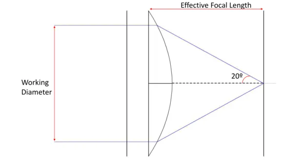
3.10 Diagram proving that for a 20°half-angle the relationship W D 2f should be equal or superior to sin(20). . . 27
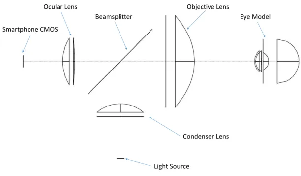
3.11 Illustration of the fundamental components in a fundus camera prototype. . 29
4.1 Original optical system. . . 32
4.3 Eye Model designed using BEAM IV. . . 34
4.4 Diagram showing the focal plane where the circle of confusion is minimum for the system designed. . . 35
4.5 Illumination path with eye at 31.5 mm from the objective. . . 36
4.6 Illumination path with eye at 36.6 mm from the objective. . . 36
4.7 Illumination path with eye at 36.6 mm from the objective with the Light-Emitting-Diode (LED) emitting at 656.27 nm (Red Light) . . . 37
4.8 Diagram showing the Imaging path with the classification of each lens having in account the position. . . 38
4.9 Imaging path with an Aspheric Lens and a PCX Lens simulation with the parallel rays model. . . 38
4.10 Simulation to check if a ray going from the smartphone CMOS parallel is focused on the retina. A PCX and an aspheric lens are used in the imaging path. . . 39
4.11 Imaging path with a Best-Form Lens as the Ocular Lens and an Aspheric Lens as the Objective. . . 40
4.12 Diagram showing the simulation used to check if a par of rays leaving the smartphone CMOS parallel is focused on the retina. . . 40
4.13 Imaging path demonstration for central rays. . . 41
4.14 Imaging path best solution for periphery rays. . . 41
4.15 Diagram showing the distance between the components in the imaging path for an eye without refractive errors (Normal Eye) . . . 42
4.16 Diagram showing the distance between the components in the imaging path for an eye with shorter focal distance (Myopic Eye). . . 43
4.17 Diagram showing the distance between the components in the imaging path for an eye with longer focal distance (Hyperopic Eye) . . . 43
4.18 Complete optical system. . . 44
4.19 Demonstration of an external fixation point. . . 45
4.20 Stitching. . . 46
4.21 Centered Internal Fixation Point being focused on the Retina. . . 47
4.22 Representation of the LED’s that will be turned on for different Pupil align-ments. . . 48
4.23 Internal Fixation points simulation for the matrix available in the market described in Figure 4.22. . . 48
5.1 Image of the previous prototype developed by Fraunhofer Portugal AICOS. . 49
5.2 Mechanical prototype designed using Solid Works in red with the rack and pinion assembly in gray and the smartphone in black. . . 50
5.3 Section view of the prototype. . . 51
L i s t o f F i g u r e s
6.1 The intensity control of the LED is performed with a smartphone application
called EFSApiTest. . . 54
6.2 Oscilloscope display, presenting the voltage change detected when the acqui-sition mode is used. . . 58
7.1 Photograph taken on the setup used to perform tests on the Imaging Path. . 66
7.2 Diagram showing the placement of the different components with the dis-tances between them represented. . . 67
7.3 Image obtained with Microsoft Lumia 360. . . 67
7.4 Image obtained for the normal eye at focus with black cardboard covering the optical path. . . 69
7.5 Image obtained for the normal eye at focus without black cardboard covering the optical path. . . 69
7.6 Image obtained for a simulated normal eye. . . 70
7.7 Image obtained for a simulated myopic eye. . . 71
7.8 Image obtained for a simulated hyperopic eye. . . 71
II.1 Diagram showing the angleα, half of the field of view in degrees. . . 87
II.2 Ray table showing the final position of the rays (Xf andZf variables). . . 88
II.3 Optics table where the position of the pupil can be assessed. . . 89
III.1 Pulse Width Modulation demonstration . . . 91
IV.1 Scheme representing the setup for acquisition of the spectrums. . . 93
IV.2 Scheme representing the setup for power measurement. . . 94
IV.3 Scheme representing the setup for the voltage measurement on the Acquisition Mode. . . 94
V.1 Spectrometer output text file . . . 95
VII.1Near Infra-Red LED Spectrums for each of the smartphone levels. . . 105
L i s t o f Ta b l e s
6.1 Near Infra-Red LED measurements . . . 55
6.2 White LED measurements . . . 55
6.3 White LED measurements . . . 57
A c r o n y m s
BRB Blood-Retinal Barrier.
DR Diabetic Retinopathy.
FOV Field-of-View.
LED Light-Emitting-Diode.
NIR Near Infra-Red.
NPDR Non-proliferative Diabetic Retinopathy.
OCT Optical Coherence Tomography.
PCX Plano-Convex.
PDR Proliferative Diabetic Retinopathy. PWM Pulse-Width Modulation.
C
h
a
p
t
e
r
1
I n t r o d u c t i o n
In this thesis, a fundus camera prototype is designed in order to help directly in the diagnose of several ophthalmologic pathologies, mainly Diabetic Retinopathy.
Before the beginning of this work, a prototype had already been developed by Fraun-hofer. The main problems present in this prototype were the amount of dispersion and the existence of undesired reflections, caused by the absence of stops and by the inner surface of the prototype reflectivity (not completely light absorbent), making it harder to acquire well-focused images. The impossibility of a continuous distance adjustment between components were other problems in this prototype. The conjunction of all these factors compromises the accuracy of the exam, making any possible medical deduction questionable, hardly allowing an indubitable diagnose. To overcome this, a new optical system as well as a 3D-printed prototype were designed.
For the design of the optical system, several lenses systems were simulated as pre-sented in chapter 4, always considering a coherent relationship between the quality and the cost of the components. The key features for the compact optical system are the mo-bile and non-mydriatic acquisition of fundus images by a smartphone camera, with a 40° Field-of-View (FOV).
Light Hazard Measurements on a previously developed prototype were also per-formed, so safety issues concerning tests in healthcare institutions can be overcome.
1.1 Context and Motivation
age [3].
The asymptomatic profile of the initial progression of DR and the high effectiveness of early treatment have motivated the implementation of extensive screening programs covering the diabetic population, in which images of the patient retinas are acquired and subsequently analyzed by an expert. However, this requires the use of relatively expensive and cumbersome equipment to acquire the retinal images as well as a time-consuming analysis of those images by ophthalmologists. The prototype EyeFundusScope, currently under investigation by Fraunhofer Portugal AICOS, aims to address these two issues by researching on a self-contained solution comprising automated diabetic retinopathy detection with a low cost optical attachment to a smartphone for retinal image acquisition. The major goal is to improve patient access to early treatment and decrease the burden of screening actions on healthcare systems all over the world.
With this work, improvements in the telemedicine field are also expected, by the ac-quisition and free-sharing of fundus photographies between nonspecialist and specialist personnel, increasing the comfort and the assiduity of the eye fundus examination.
1.2 Objectives
The 3 principal objectives targeted during this thesis were:
• Design of a compact optical system for fundus photography with no need of pupil dilation, ensuring 40º field-of-view with a uniform illumination in all the desired area, comprising several pupil alignments;
• Design of a 3D-printed mechanical prototype for support of the optical system, facilitating transportation and handheld screening;
• Light Hazard measurement on a previously developed fundus camera prototype.
The design of a compact, small optical system urges since there is the need of an hand-held smartphone based device for easy transportation and to be used in under-developed countries. The requirements on the field of view and the no need of pupil dilation are essential for an easy acquisition, easily performed by individuals with no experience on ophthalmology or orthoptics enhancing the role of the telemedicine in the global health-care. Are comprised the acquisition of ocular fundus photographs, its share with the doctor, the medical appreciation and finally, the communication of the diagnose to the patient. In the optical system the implementation of internal fixation points will also be addressed. The existence of internal fixation points will also be a very important feature for the prototype. By giving the patient a target to be staring on, the eye movements are prevented, furthering the idea of a non-specialized examiner.
1 . 3 . OV E RV I E W
The light hazard measurement on the previous prototype was also accessed, regarding two different ISO norms, ISO 15004-2[4] for Light Hazard Protection on Ophthalmic Instruments and ISO 10940[5] for fundus cameras. For each LED, both the power emitted and the spectrum were obtained as well as the power emitted during the acquisition of the image (flash of the smartphone camera).
1.3 Overview
This dissertation is divided in 8 chapters. In this one, are explained the initial problem and the objectives expected to be achieved by end of this thesis.
In chapter 2, Diabetic Retinopathy, the disease whose diagnose and morbidity is in-tended to be diminished by the work developed during this thesis, is explained, as well as the fundamental characteristics of a fundus camera, the instrument to be designed.
In chapter 3, there is a guide for the optical system design software, BEAM IV, as well as an explanation of several optical principles, helpful in the achievement of an accurate optical system.
Chapter 4 presents the different optical simulations performed, the human eye, the optical system in the previous prototype, the developed optical system with an explana-tion on the adjustments needed for patients with different refractive errors and the design of internal fixation points.
In chapter 5, the mechanical prototype designed for the casing of the optical system is presented along with the specifications required.
In chapter 6, a description of the Light Hazard Measurements along with a ISO Norms compliance test is presented.
In chapter 7, the Imaging path, designed in BEAM IV, practical tests performed in an optics laboratory are described. The Imaging path for refractive errors tests are also addressed.
C
h
a
p
t
e
r
2
D i a b e t i c R e t i n o pa t h y
Diabetic Retinopathy is a microvascular consequence of diabetes, characterized by the loss of pericytes and by a progressive capillary occlusion that occurs mostly without symptoms. The capillary occlusion can lead to retinal ischemia and to the breakdown of the blood-retinal-barrier[6]. As the Diabetic Retinopathy (DR) advances, the risk of blindness increases. In addition, patients with DR have higher chances of contracting coronary heart disease, stroke, diabetic nephropathy, or amputations [7]. The major risk factors are the existence of diabetes mellitus condition, poor glycemic control and hypertension [8, 9].
In addition to a strict systemic control of glycemic, lipid, cholesterol and blood pres-sure levels, routine ophthalmologic examination has a vital role in the early identification of diabetic retinopathy, facilitating the treatment of the disease in a initial stage[10, 11].
The DR is commonly divided in two different stages: Non-proliferative Diabetic Retinopathy (NPDR) and Proliferative Diabetic Retinopathy (PDR). The first is char-acterized by abnormalities in the blood vessels, materialized in the leakage of substances from the lumen of the vessels to the retinal epithelium. The leakages may be the blood itself leading to microaneurysms and intraretinal hemorrhages, and lipids leading to hard and soft exudates [11–13]. It is classified according to its severity in [11–13] :
• Mild- at least one microaneurysm;
• Moderate - presence of blood hemorrhages;
• Severe (4-2-1) - more than 20 hemorrhages in4 quadrants, vessel distensions in2 quadrantsor intrarretinal microvascular abnormalities in1 of the quadrants.
than the previous ones, increase the risk of bleeding and do not solve retinal ischemia [13]. In this stage there is also the formation of fibrous tissue that while contracting can provoke retinal detachment[15].
The DR is a disease that ultimately can lead to complete vision loss (Figure 2.1) and its high morbidity is statistically proven, affecting 76% of the diabetic patients for longer than 20 years [2], being the leading cause of blindness in adults with working age [3].
a Vision showing no significant visual deficiencies. b Possible vision of a person with Diabetic Retinopathy.
Figure 2.1: Visual differences between an ophthalmological healthy person and a person with Diabetic Retinopathy. Both Images were obtained in a presentation supplied by Fraunhofer Portugal AICOS.
2.1 Pathology Progression
In the DR, mainly due to the exaggerated glucose level in the blood, several changes in the blood vessels occur. These changes consist in the thickening of the walls, reduc-tion of the gauge, consistency, elasticity and permeability alterareduc-tions, which lead to the symptoms progression as described in the following subsections [14, 16].
2.1.1 Non-Profilerative Diabetic Retinopathy
• Microaneurysm (Figure 2.2) :
2 . 1 . PAT H O LO G Y P R O G R E S S I O N
Figure 2.2: Image of a microaneurysm [12].
• Intrarretinal Hemorrhages (Figure 2.3):
Caused by capillary rupture [12]. Can present a rounded shape, as microaneurysms, or have an undefined shape [13].
Figure 2.3: Image of an intrarretinal hemorrhage [12].
Consist in the deposition of big chains of lipids or peptides, leaked from the blood vessels, on the retina. Usually, are yellow and can be grouped, as can be seen in Figure 2.4 [12, 13].
Figure 2.4: Image of an exsudate [12].
• Diabetic Macular Edema:
Macular Edema is characterized by an increment on the thickness of the macula caused by the breakage of the Blood-Retinal Barrier (BRB), provoking the leakage of liquid from the lumen of the vessels to the retinal epithelium [18]. May not be seen in fundus photographs, although a notorious presence of exudates may indicate this complication. Is the main cause of blindness in patients with type 2 diabetes [13].
2.1.2 Profilerative Diabetic Retinopathy
• Neovascularization (Figure 2.5):
2 . 1 . PAT H O LO G Y P R O G R E S S I O N
Figure 2.5: Neovascularization derived vessels covering the Optical Disk [12].
• Fibrous Tissue Formation
During this stage of DR the new vessels become bigger and the formation of fibrous tissue takes place [19].
• Retinal Detachment (Figure 2.6)
When the fibrous tissue contracts, the retina can be tractionally detached from the fundus, leading to serious vision losses [19].
2.2 Treatment
The treatment for diabetic retinopathy in early stages, goes through the control of the blood sugar and the blood pressure by reducing the intake of fats, as any patient with diabetes should do. To prevent the onset of the disease, ocular exams should be performed regularly [20]. In more severe cases more invasive treatments are necessary. Some examples of them will be numbered and briefly explained below:
• Photocoagulation :
It is a therapy that can be used to prevent the evolution of diabetic retinopathy, from non-proliferative to proliferative. It destroys the new vessels and seals the vessels that leak fluids and other substances. In macular edema, for example, the objective is to avoid the extravasation of more liquid, for which the vessels are sealed at the periphery of the macula [21] [20].
• Vitreoretinal surgery :
The vitreoretinal surgery consists on removing the blood released in the vitreous hemorrhages and the vitreous humor itself. The vitreous humor is replaced by a gas or silicone oil. This surgery is applied in more advanced cases of proliferative diabetic retinopathy in which there are bleeds in the vitreous humor and retinal dis-placements. It is important to notice that vessels which cause retinal displacement are also removed [22] [20].
• Antiangiogenic Drugs :
Drugs that inhibit the Vascular Endothelial Growth Factor (VEGF). Often used, pre-venting the creation of new vessels. Are mostly used to prevent the progression of proliferative diabetic retinopathy and usually are delivered through an intravitreal injection [23] [20]. Alongside with its neovascularization preventive capabilities, nefarious secondary effects like hypertension or impairment of wound healing can appear [23].
2.3 Diagnosis
2 . 3 . D I AG N O S I S
fundus camera, the next subsection will explain those more specifically. The Figure 2.8 shows an example of a fundus photograph.
2.3.1 Fundus Camera
A fundus camera is a device based on indirect ophthalmoscopy principles and because of that, allow a considerable FOV without pupil dilation (Figures 2.7 and 2.8). Pupil dila-tion is usually achieved by the use of mydriatic agents which are usually uncomfortable for the patient [28].
a Direct Ophthalmocscopy Method [29]. b Indirect Ophthalmocscopy Method [29].
Figure 2.7: Illustration of the comparison between direct and indirect opthalmoscopy methods. As can be seen by the usage of a condensing lens between the observer and the patient the Field of View can be increased[29].
Figure 2.8: Eye Fundus image where Blood Vessels, Macula and the Optic Disk can be seen [30].
fields, with positive responses in Neurology ( by relating retinal problems with strokes and cognitive problems) and in the assessment of cardiovascular risks, among others [31, 32].
A handheld portable fundus camera can also be a crucial tool in the development of telemedicine, which can be defined as the consultation between physicians or between physicians and patients by means of telecommunications [31]. The efficiency of this field is very dependent on the capacities and quality of the healthcare technological equip-ment. In this case, when the fundus examination can be performed by non-specialized individuals with a high success rate, the fundus camera becomes a valuable tool for the evolution of distance monitoring [31]. This monitoring, in addition to being extremely useful in hospitals, reducing waiting time, is fundamental in less developed areas or in patients with limited access to specialized care. As far as ophthalmology is concerned, telemedicine presents high success rates even when compared to the traditional on-site examination, being its main problem of implantation, the privacy protection and the confidentiality of the photographs obtained [31, 33].
2.4 Related Work
The improvement on the capabilities of handheld devices described in the subsection 2.3.1 led to a variety of different approaches. Some examples that reflect the recent scientific development are:
• Nonmydriatic Fundus Camera Based on the Raspberry Pi® Computer: Uses the
Raspberry Pi®camera module coupled with a Condenser Lens to perform fundus
imaging with a very low production cost [34].
• Eye-Selfie: By the usage of internal fixation points as targets, allows an acquisition of the fundus photograph, entirely self-performed by the patient [35].
As for ophthalmic devices available in the market, some prototypes are described next. The following reviews are based on information provided on the companies websites [36– 38].
2.4.1 D-Eye Portable Retinal Imaging System
The D-EYE (Figure 2.9) is a smartphone coupled system which allows regular eye screenings, giving information about potential eye diseases and capturing images for future evaluation of each patient’s medical condition. The features allowed are :
• Field of View up to 20º with pupil dilation;
• Field of View up to 6º without pupil dilation;
2 . 4 . R E L AT E D WO R K
• Ergonomic;
• Removes corneal reflexes;
• Store patient history in a file;
• Allows the review of pre and post-treatment images;
• Sharing of images;
• Compatible with all versions of the Iphone after the Iphone 5.
Figure 2.9: [Image of the D-EYE Ophthalmoscope coupled to an Iphone [36].
Although the D-EYE system is ergonomic and has great ease of use, it has a large gap, as previously mentioned, present in all ophthalmoscopes. An acceptable FOV is only obtainable through the use of mydriatic agents. In practical terms it allows the diagnosis of diabetic retinopathy only in advanced stages. There is the need of an external applicator to attach to the mobile phone at a cost of 99.00e. The cost of the device is 395.00e, thus
having a total price of 494.00e.
2.4.2 Volk InView - Iphone Fundus Camera
The Volk iNview (Figure 2.10) is a fundus camera attached to a smartphone that allows the acquisition of retinal images. The free download application allows an automatic image capture during a query, choosing the most focused and defined images for fast acquisition. The application is secure in that it is encrypted with a password, ensuring, even in case of loss or theft of the Iphone, the confidentiality of the images.
• Free smartphone App;
• 1 Megapixel resolution with a static FOV of 50°;
• 80° dynamic imaging of the periphery of the retina;
• Both manual and automatic acquisition modes;
• Requires a 5mm pupil;
• Storing and uploading from the Iphone to the computer;
• Compatible with 5S/6/6S versions of the Iphone and with the Ipod Touch (Gen6);
• Compatible with all versions of the Iphone from the Iphone 5.
Figure 2.10: Image of the Volk Inview coupled to an Iphone [38].
Costing 1.495.00$, is the lowest costing solution, supplied by Volk. The low resolution and the need of pupil dilation are the main problems in this device.
2.4.3 Volk Pictor Plus
2 . 4 . R E L AT E D WO R K
• Portable (weights 0.45 kg);
• Image uploading to any Personal Computer or mobile device;
• 40° field-of-view in the Retinal module ;
• 9 Fixation Points for imaging of several retinal areas;
• Non-mydriatic;
• Possibility of red-free imaging;
• Both manual and automatic acquisition modes;
• Angiography module.
a Volk Pictor Plus fundus camera. b Fundus Image acquired with the Volk
Pic-tor Plus.
Figure 2.11: Volk Pictor Plus [37].
At the date of the realization of this dissertation costed 9.995.00$. The Pictor Plus is a complete device that can be really helpful in several pathologies. The only main outcome ends up being the high price.
2.4.4 Fraunhofer EyeFundusScope
Before the beginning of this work, a prototype had already been developed by Fraun-hofer. The system proposed differs from the previous approaches by using a smartphone for non-mydriatic retinal image acquisition. The use of a smartphone instead of cus-tom electronic devices for image capture and processing allows a substantial decrease in costs while allowing for a very high image quality and resolution, thus guaranteeing the cost-effectiveness of the overall solution.
Figure 2.12: Image of the previous prototype developed by Fraunhofer Portugal AICOS.
C
h
a
p
t
e
r
3
I n t r o d u c t i o n t o O p t i c a l S y s t e m D e s i g n
To design an optical system, a wide background knowledge, namely, in the field of Optics must be taken in account. In this chapter, several optical principles and tools, are explained and described. To understand the simulation software a small guide on the use of BEAM IV is presented as well as the simulation process tools with the description of the two ray tracing models needed for the evaluation of the capabilities of the optical system. As for the lenses, the types of lenses used during this work will be addressed along with a small description of existent optical aberrations caused by them.
3.1 Ray Tracing
Ray Tracing can be defined as a technique for image synthesis that consists in the systematic computation of the progression of rays of light through an optical system [39].
When the capacities of the computers weren’t sufficient, the physicians plotted on paper the path taken by the rays, starting in a light source and then passing through the optical components. In the early 1970’s, when the machines got fast enough, the optical modulation became available using computers and the appearance of a variety of software, made the ray tracing one of the very first numerical activities to be adapted to the computer [39]. One of the softwares is BEAM IV described in the following section.
3.2 BEAM IV
BEAM IV is a table driven ray tracer software provided by Stellar Software. Being table driven means that the only inputs that need to be supplied to the system are text files containing tables.
This tables can be divided in different types, discriminated by the extension of the respective text file, being :
• Optics tables (.OPT).
• Ray Tables (.RAY).
• Medium Tables (.MED).
3.2.1 Optics tables
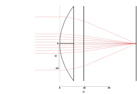
Describe the components (lens, mirrors...) of the optical system to be traced, present-ing a set of optical characteristics for each component. These characteristics provide a realistic simulation of the components and make BEAM IV a reliable tool for the design of optical systems. The result of its usage can be seen in figure 3.1 as there is presented the table for simulation of an aspheric lens with a diameter of 30 mm and a goal surface at its focal length. The figure 3.1b shows the layout computation of the table. The following variables are the ones considered along the work progress in this thesis.
• Type:
Specifies the type of each surface. Only the first letter is taken in account by the software. The different types allowed are lenses (represented by an l), mirrors (represented by an m), irises (represented by an i) or goals (final surface, represented by any initial letter, different than the previous ones). An Iris is a surface that don’t change the ray direction only defines maximum and/or minimum radii of ray passage.
• Index:
Refractive index of the medium approaching the surface. The default is 1.0.
• X, Y, Z:
Lab coordinates for the center of each surface.
• Diameter:
Diameter of the outer periphery of the surface.
• T, P, R:
3 . 2 . B E A M I V
• Curv:
Curvature of the surface; Value = 1/radius of curvature.
• Asph:
Asphericity is the departure from the spherical profile of a surface. Really help-ful for the simulation of aspheric lenses, described in the section 3.4, and used throughout this dissertation.
a .OPT Table for the simulation of the lens. b Diagram of the Aspheric lens described using the
Layout BEAM IV tool.
Figure 3.1: Computation of an S-LAH64 Aspheric Lens with 30 mmφ.
3.2.2 Ray tables
The input data supplied in these tables describes how the system is to be illuminated, by reporting the initial attributes of the light rays. Its importance is reflected in the amount of output data provided by them, informing not only the position and direction of the rays on the final surface, but also at any intermediate component. These features make Ray Tables the most relevant, in summarizing the results of any trace.
The implementation of the rays in the optical system leads to a much easier to inter-pret representation, as can be seen in Figure 3.2. The description of the used variables is presented next.
• Input data:
The variables for the input data are the wavelength, specifying the wavelength for each ray, and the coordinates for ray start, having the pair (X0,U0) for the position and direction along the x-axis, (Y0, V0) for the y-axis and (Z0, W0) for the z-axis, respectively. The coordinates for the direction are the tangent of the angles rays make with the axis. For example, to compute a ray whose direction is of 20º with the x-axis, the U0 coordinate should be tan(20°) = 0.363.
ray. The goals are very important with some features like the Auto-Adjustment and the In-Out, described hereinafter.
• Output data:
As mentioned before, the ray table can be set up to receive selected output data from any ray trace. To do this, appropriate output field labels need to be in the table header. The labels for the position at any surface are labeled with the axis and the number of the surface, for example, if one wants to know the position of the ray along the x-axis in the third surface, the label is X3. To have information in the final surface, the label is simply the label of the variable (X,Y,...) followed by the f letter (Uf for example, asks the software for the final direction of the ray relating to the x-axis). Other really important label is Notes, whose outputs describes the final destination of the ray. If the rays reach the final surface, the output is OK if they don’t, the output informs on where and why the rays struggled (mis for missing surface, Dia for intercepting a surface beyond it’s outer diameter...).
Figure 3.2: Diagram showing the simulation of the optical system described in Figure 3.1 with the addition of a .RAY Table.
3.2.3 Medium tables
3 . 2 . B E A M I V
BEAM IV. The creation of new tables is possible and allows the selection of only the relevant glasses for each project.
3.2.4 Helpful BEAM IV Tools
Once the tables are defined, BEAM IV provides several tools in the RUN Menu that allow the understanding of the capabilities of the system modulated. The ones used during the realization of this thesis are the following.
• Layout:
When selected, this tool simply shows the drawing of the system with the possibility of seeing different perspectives at different distances from the system (Zoom In and Out). It was the used tool to get the diagrams from figures 3.1 and 3.2.
• InOut:
As the name suggests, this tool gathers the inputs from the tables and by the com-putation of the rays fills the output information on the ray tables (Notes,Xf,Uf...). When there are goals defined this feature also calculates the RMS, root mean square deviation, between the final coordinates and the goals.
• Plot 2D:
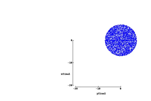
This function provides a way to view relationships between any two ray trace vari-ables. It is really important to show the arrival positions of the rays at the final surface of the optical system. In this project it was used with the Random tool so the uniformity of the illumination could be checked.
• Histo 2D:
The Histo 2D is a view of the relative frequency of any pair of ray variables. Dur-ing this project was used in the same way that the Plot 2D, also coupled with the Random command.
• Random:
The Random tool fulfills gaps between the rays defined in the Ray tables. Five probability distributions are available: the most common is the uniform distribu-tion which gives equal probability for all ray start values within your start range. Cosine is centrally peaked, and Quartic Bell is bellshaped and more concentrated. Gaussians and Lorentzians offer specified concentration = half width of your span divided by the 50% probability width of the distribution. In this project only the uniform distribution will be used. An example of its use coupled with Plot 2D is shown in figure 3.3.
• AutoAdjust:
Really helpful in the setup of some continuous parameters, like the Radius of Cur-vature or the positions of the surfaces and the rays. With this feature it’s intended to diminish the value of the RMS. To autoadjust any variable only the tag letters must be changed. To change it independently from the rest of the system, the tag must be a question mark, to change a group of variables in the same way they need to be tagged with the same letter. Although it only works when the rays reach the final surface. If they don’t, this command cannot be executed.
3.3 Optical Aberrations
To be in agreement with the optical capabilities needed there is the need of a system with minimized aberrations. To achieve it, first, some knowledge about optical aberrations and the different existent types is necessary. An optical aberration can be defined as the existence of different focal lengths for different rays of light when passing through the same lens [41]. Can be divided in the following groups :
• Chromatic Aberrations:
Consist in the existence of different focal lengths for rays of light of different wave-lengths. Are caused by the different refractive indexes any transparent material demonstrates for different wavelengths [42]. The medium table in Figure?? demon-strates the refractive index variation.
• Symmetrical Monochromatic Aberrations:
3 . 4 . T Y P E S O F L E N S E S
to the lens than the paraxial rays [41]. Usually, representative in lenses with a great diameter.
• Asymmetrical Monochromatic Aberrations:
The Asymmetrical Monochromatic Aberrations are caused by rays with a direction that doesn’t match the optical axis, which can also be called off-axis rays. One of the different kinds is named Coma due to the "cometlike" appearance of the image produced [41] and will be addressed later on this dissertation. The Figure 3.4 demonstrates the formation of Coma.
Figure 3.4: Coma explanation. The rays passing through the center of the lens are focused in a different region than those passing through the periphery (called marginal rays in the figure). The further from the center, the further from the chief ray focal point (A’), the rays will be focused [41].
As the desired system only comprises 3 lenses, the minimization of the aberrations will be attempted with the use of high quality components, with spherical aberration correction.
3.4 Types of Lenses
To reach the best optical system, several lenses were tested, namely :
• Plano-Convex (PCX) Lens:
• Bi-Convex Lens:
Lenses composed of two convex surfaces. Can be used in many finite imaging models but as can be seen in Figure 3.5 lead to many spherical aberrations.
Figure 3.5: Bi-Convex lens showing too many aberrations.
• CNC-Polished Aspheric Lens:
Lenses that provide a sharp image focus while minimizing image aberrations. Com-posed by one elliptical (non-spherical) surface characterized by an Aspheric coef-ficient, usually described with the letter k, related with the shape of the surface. These surfaces major contribute is in the minimization of monochromatic aberra-tions. Other of the advantages of these lenses when compared with others is that they are available in the market with largest diameters, providing a bigger numeri-cal aperture.
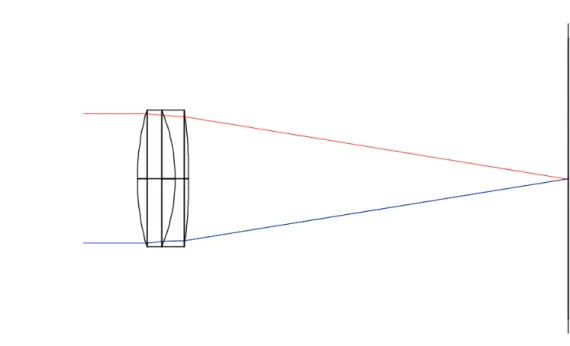
• Achromatic Lens:
Lenses whose main goal is to prevent the occurrence of chromatic aberrations when used in the visible part of the electromagnetic spectrum, allowing really small focal length shifts for radiation at different wavelengths, as can be seen in Figure 3.6. The system doesn’t present many chromatic aberrations so these lens were excluded from the final optical system. Other reason for excluding them, is related with the fact that the achromatic lens available in the market don’t have the sufficient capabilities (Diameter and Dioptric power) to allow the imaging of 40º of retinal area.
3 . 5 . R AY T R AC I N G M O D E L S
Figure 3.6: Achromatic lens performance, showing similar focal length for different wave-lengths.
Lenses characterized by 2 spherical surfaces but with a combination of curvatures that minimizes the spherical aberrations.
3.5 Ray tracing models
3.5.1 4-Extremes Model
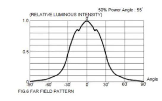
This model assumes that the light source emits from a single point with a certain aperture previously declared by the manufacturer. The value usually comes declared as presented in Figure 3.7 and the angles for which the relative luminous intensity is bellow half the maximum intensity can be neglected.
So, for example, for the LED with the graph in Figure 3.7 the four extremes model describes four rays beginning at the exact same position, having the angle of 30º as the maximum deviation from the normal. To implement the rays, it is needed to calculate the tangent of 30°, which is equal to 0.577.
Figure 3.7: Graph of the luminous intensity of the LED relative to the angle with the normal.
Figure 3.8: Ray table with rays for the 4-extremes model.
3.5.2 Parallel Rays Model
3 . 6 . O B J E C T I V E L E N S CO N D I T I O N
Cornea
Pupil
Lens
Center of the Retina Periphery of the Retina
Figure 3.9: Illustration of the parallel rays model. In this figure rays are focused on the retina, leaving the pupil collimated and parallel.
3.6 Objective Lens Condition
As in most fundus cameras, for retinal illumination, there is a lens above the light source to collimate the rays and another lens to focus the rays. This lens that focus the rays before reaching the eye is called objective lens.
Working Diameter
Effective Focal Length
20º
Figure 3.10: Diagram proving that for a 20°half-angle the relationship W D
2f should be
To obtain a field-of-view of 40° there is a constraint that the relationship W D
2f should
be superior to sin(20°) (see Figure 3.10), whereW D stands for Working Diameter and f means the effective focal length of the lens. As can be seen in the diagram in the fig. 3.10 one can be easily mislead to use the tangent, but the usage of the sine is justified by the fact that the lens principal planes must be regarded as curved surfaces when the rays reach beyond the paraxial region, as it is declared by the Abbe sine condition [43].
3.7 Fundus Camera Components
In this work, to diminish the production costs, only the fundamental components of a fundus camera were used. A field-of-view of at least 40° is desired, since this is generally considered an adequate tradeoff between sufficient retinal area imaged and enough resolution for analysis of finer retinal features, thus allowing clinical meaningful conclusions about eventual abnormalities.
3 . 7 . F U N D U S CA M E R A COM P O N E N T S
Ocular Lens
Light Source
Condenser Lens Beamsplitter
Objective Lens
Eye Model Smartphone CMOS
C
h
a
p
t
e
r
4
O p t i c a l S y s t e m D e s i g n
In the present work, it is proposed a simple Fundus Camera optical system, using only 3 lenses, allowing a 40º field-of-view with minimized aberrations and no need of pupil dilation. In this chapter the simulation performed using BEAM IV will be described. The simulated systems will be, a model of the eye to accurately check systematic optical capabilities, the optical path taken by the rays, internal fixation points for different pupil alignments as well as adjustments needed for eyes with refractive errors.
Usually, to design a Fundus Camera the usage of a beamsplitter is needed in order to keep the coaxiality between the illumination and imaging optical paths. This means that the optical path for simulation, must be separated in two different paths. The illumination path, describing how the rays go from the light source (LED) to the retina and the imaging path, describing how the rays go from the retina to the Sensor, in this case, the smartphone camera.
4.1 Previous Optical System
Before the beginning of this thesis, there already was a fundus camera prototype. The optical system for this prototype is presented in Figure 4.1 and was composed by :
• A Visible LED:
As a light source, a Visible LED emitting white light with 60º viewing angle was used, giving rise to a lot of dispersion.
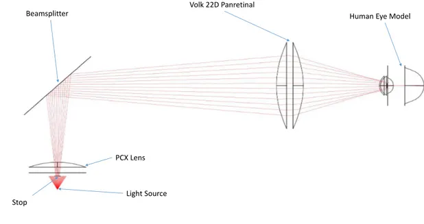
• Volk 22D Pan retinal Lens (Aspheric Lens with 52mm Diameter) :
• Non polarizing Beamsplitter 50R/50T (35x35mm):
The Beamsplitter has the purpose of separating one incident light ray in two sep-arate beams. Being 50R/50T means that it splits the original ray of light into two different ones with half of the intensity of the original one. In BEAM IV, the reflec-tive and transmissive strands must be simulated separately. For the reflecreflec-tive, the beamsplitter is considered a mirror and for the transmissive it is omitted.
• Edmund Optics Plano-Convex Lens 20 D (30 mm diameter)
The Plano-Convex Lens is used as a Condenser Lens with a purpose of collimating the divergent beams coming from the light source.
• B + W 40.5mm +4 Close Up Glass Filter - NL4
A Close-Up lens is a magnifying lens which allows a larger image scale.
Beamsplitter Volk 22D Panretinal Human Eye Model
PCX Lens
Light Source
Figure 4.1: Original optical system.
4 . 2 . H U M A N E Y E M O D E L
Beamsplitter
Volk 22D Panretinal
Human Eye Model
PCX Lens
Light Source Stop
Figure 4.2: Demonstration on how the utilization of stops can prevent dispersion, in the previously developed optical system.
4.2 Human Eye Model
To guarantee a satisfactory field-of-view, an accurate model of the eye is needed. The eye has two refractive lenses, the cornea and the crystalline lens. Based on the literature [44] and following a similar approach to [45], a model of the eye was created in BEAM IV considering the radius of curvature, diameter and asphericity coefficients of all the structures relevant for ray tracing. The pupil has been designed with a 4 mm diameter to simulate a non-mydriatic acquisition and is coincident with the lens anterior surface. The chromatic aberrations from the eye were neglected as the change in diopters at different wavelengths were not considered significant in the scope of this work [44].
The defined structures of the eye, as represented in Figure 4.3, are:
• Corneal Anterior surface:
Diameter = 11.50 mm
Radius of Curvature = 7.75 mm Asphericity coefficient = -0.2
• Corneal Posterior surface:
Diameter = 11.50 mm
Radius of Curvature = 6.8 mm Asphericity coefficient = 0
Diameter = 4 mm
Radius of Curvature = 10 mm Asphericity coefficient = -0.94
• Lens Posterior Surface:
Diameter = 9 mm
Radius of Curvature = -6 mm Asphericity coefficient = 0.96
• Retina:
Diameter = 24 mm
Radius of Curvature = 12 mm Asphericity coefficient = 0
Anterior Cornea
Posterior Cornea
4 mm Pupil
Retina Lens
Figure 4.3: Eye Model designed using BEAM IV. Rays at infinity being focused on the retina.
4.3 Illumination Path
4 . 3 . I L LU M I N AT I O N PAT H
As in several handheld fundus camera designs [25, 46], there is a lens above the light source to collimate the rays and another lens to focus the rays. This lens that focus the rays before reaching the eye is called objective lens and it is where the simulations described in this dissertation began. The type of objective lens chosen should minimize spherical aberrations. This condition, coupled with the required numerical aperture (section 3.6), makes Aspheric lenses the only suitable option for the focusing of the rays when reaching the retina. After searching for a lens that fits these requirements the option ended up being a Thorlabs Aspheric Lens with 50.00 mm diameter, 40.00 mm focal length and SLAH-64 glass type, placed 25 mm ahead to the right of the center of the beamsplitter. For the collimation of the rays coming from the light source, the used Condenser lens was an Edmund Optics Plano-Convex Lens with 25.4 mm diameter, 38.1 mm focal length and N-BK7 glass type, placed 47 mm below the center of the beamsplitter.
To check the distance between the objective lens and the human eye, the plane where the rays were in focus was calculated. This plane is called the focal plane and is where the circle of confusion is minimum. In a theoretically aberration free-system, this is where the pupil should be placed to ensure that a great part of the rays reach the retina and are not reflected by the white surface of the cornea. These tests were performed for a blue light with 486 nm wavelength and are represented in Figure 4.4.
PCX Lens
Beamsplitter Aspheric Lens
Light Source
Focal Plane
Figure 4.4: Diagram showing the focal plane where the circle of confusion is minimum for the system designed.
The measured distance from the curved surface of the objective lens to the focal plane was 31.5 mm.
spherical aberrations, resulting in a 40% transmittance. The existence of these aberrations is very usual in lenses with a great diameter as the one used as an objective.
A description on how the FOV was calculated is done on the annex II. The procedure for the calculation of the FOV will be the same throughout this dissertation.
PCX Lens
Beamsplitter Aspheric Lens
Light Source Eye Model
a Representation of the Illumination path. b Retinal illumination profile showing that the
in-termediary rays don’t reach the retina, preventing a proper illumination.
Figure 4.5: Illumination path with eye at 31.5 mm from the objective.
Using the AutoAdjust tool it was possible to see that the pupil, to accomplish a uni-form illumination of the retina, should be placed at 36.6 mm from the objective, this means the eye must be moved away 5 mm from the objective. Using this different configu-ration, 90% of the emitted rays reach the retina and the illumination profile is uniform, as can be observed in Figure 4.6. The half-angle on the retina calculated was 20.66° leading to a total field-of-view of 41.32°.
PCX Lens
Beamsplitter Aspheric Lens
Light Source Eye Model
a Representation of the Illumination path. b Retinal illumination profile showing illumination
uniformity.
Figure 4.6: Illumination path with eye at 36.6 mm from the objective.
4 . 4 . I M AG I N G PAT H
of the lenses, causing the rays to intercept the optical path in a little different position, than they do with a blue light. As the white light consists in the addition of several different wavelengths, a 92 percent efficiency at one end (red) and 90 percent at the other (blue) makes this system considerably reliable.
PCX Lens Beamsplitter Aspheric Lens
Light Source Eye Model
a Representation of the Illumination path b Retinal illumination profile showing uniformity
Figure 4.7: Illumination path with eye at 36.6 mm from the objective with the LED emitting at 656.27 nm (Red Light)
4.4 Imaging Path
For the imaging path the key features desired are the almost complete fulfillment of the smartphone camera sensor and the minimization of aberrations. These characteristics can be verified using the parallel ray model. In order to perform a forward ray tracing analysis of the imaging path, two pairs of parallel rays were considered, one pair parallel with the optical axis and the other with 20° inclination. The distance between the rays, on each pair, was equal to the size of the pupil, 4 mm. The imaging path is presented in Figure 4.8.
The system was optimized for a LG Nexus 5X camera whose relevant specifications are:
• Horizontal angle of view : 68.2°
• Vertical angle of view : 53.1°
• Sensor size : 1/2.3"(6.17 x 4.55 mm)
Ocular Lens Objective Lens
Pupil Smartphone Camera
Figure 4.8: Diagram showing the Imaging path with the classification of each lens having in account the position.
The system achieved, represented in Figure 4.9 had very different inclinations on the CCD, one having 25.6º and the other having 23.2º.
PCX Lens Aspheric Lens
Pupil Smartphone Camera
Figure 4.9: Imaging path with an Aspheric Lens and a PCX Lens simulation with the parallel rays model.
4 . 4 . I M AG I N G PAT H
same direction, four at the extreme solution with 25.6º inclination and four at the center, parallel to the optical path. The rays start position is equally distant from the origin at the positive and negative directions of the x and y-axis. In a non-aberrative system both extreme and center rays should focus at a similar distance from the Ocular but as can be verified in Figure 4.10, that doesn’t happen. This difference is problematic when the rays reach the retina, not providing a satisfactory image of the human eye.
PCX Lens Aspheric Lens
Eye Model Smartphone Camera
Figure 4.10: Simulation to check if a ray going from the smartphone CMOS parallel is focused on the retina. A PCX and an aspheric lens are used in the imaging path.
To correct the aberrations, as the Objective Lens already fulfilled the requirements for the illumination path, the Ocular Lens was changed. A Best-Form Lens with 40.0 mm focal length, 25.0 diopters and 25.4 diameter was tested. The aberrations were almost eliminated and the rays reached the smartphone camera parallel to each other, with an inclination of approximately 22 °, leading to an angular field-of-view of 44°. The diagram can be seen in Figure 4.11. The angle in this configuration is inferior to the achieved with the PCX lens as an ocular, but still wide enough to avoid a significant crop.
In this setup the distance between the smartphone CMOS sensor and the Best-Form Lens is 22 mm. The distance between the surface of the Best-Form Lens with less curva-ture and the planar surface of the Aspheric Lens is 50 mm and between the Aspheric lens and the eye is 33 mm. In Figure 4.12, using backward ray tracing, it is visible that the results were improved, comparing with the previous solution. The focusing of the image is a little after the retina for the center rays, as for the extreme rays is a little before.
Best-Form Lens Aspheric Lens
Pupil Smartphone Camera
Figure 4.11: Imaging path with a Best-Form Lens as the Ocular Lens and an Aspheric Lens as the Objective, using the parallel rays model, showing better capabilities than with the PCX Lens.
Smartphone Camera
Best-Form Lens Aspheric Lens
Eye Model
4 . 4 . I M AG I N G PAT H
Figure 4.13 by moving the eye 4 mm away from the objective the focus in the center can be improved as for the extreme rays the best solution is accomplished by approximating the eye 1 mm to the objective, described in Figure 4.14. At the extreme rays an aberration type called coma (described in the section 3.3) is visible. These aberrations occur when the image is off-axis and result in a asymmetric image.
Best-Form Lens Aspheric Lens
Eye Model Smartphone Camera
a Imaging path best solution for central rays. b The minimum circle of confusion is obtained by
moving the eye 4mm away from the center.
Figure 4.13: Imaging path demonstration for central rays. The eye is moved away from the system 4mm. The rays leave the Smartphone CMOS parallel and are focused on the retina. The figure on the left shows the minimum circle of confusion (≈0.3 mm) when reaching the retina.
Best-Form Lens Aspheric Lens
Eye Model Smartphone Camera
a Imaging path best solution for periphery rays. b Periphery rays retinal profile
4.5 Imaging Path for Eyes with Refractive Errors
Eyes with refractive errors present different optical characteristics and so, the position of at least one of the lenses in the optical system must be adjustable to compensate this. As the smartphone camera is able to change its focus target distance, the refractive errors were modulated in the range of -5D to +5D. Since one of the possible cause of refractive errors is the size of the eyeball [47], for the modulation of Myopia the retina was moved 3 mm away from the refractive center of the eye. Concerning the modulation of Hyperopia the eyeball was shortened 3 mm. Considering that the eye refractive power is approximately 60 D [44], by the use of the equation I.2 for changes of -5D and +5D, the focal length will change +1.18 and -1.7 mm, respectively. The value chosen was 3 mm to give margin for slightly bigger refractive errors. In Figure 4.15, the system configuration for an eye without any refractive error is shown. In Figures 4.16 and 4.17 are presented diagrams showing the adjustments done to compensate these refractive errors. For the Myopic eye the error is corrected by moving the Objective Lens 5 mm away from the eye. Concerning the Hyperopic eye, the Objective lens is approximated 5 mm to the eye.
22 mm 50 mm 36,5 mm 20,6mm
(Pupil)
4 . 5 . I M AG I N G PAT H F O R E Y E S W I T H R E F R AC T I V E E R R O R S
22 mm 45 mm 41,5 mm 23,6mm
(Pupil)
Figure 4.16: Diagram showing the distance between the components in the imaging path for an eye with shorter focal distance (Myopic Eye).
22 mm 55 mm 31,5 mm 17,6mm
(Pupil)
4.6 Complete Optical System
With the illumination path and imaging path developed the complete optical system presented in Figure 4.18 has the following components1:
• Light Source (Visible or Near Infra-red LED).
• N-BK7 Plano-Convex Lens, 38.1 mm Focal Length, 25.4 mmφ, VIS-NIR Coated,
44,00e, Edmund Optics.
• S-LAH64 CNC-Polished Aspheric Lens, 40.0 mm Focal Length,50 mmφ, 392,00e,
ThorLabs.
• Beamsplitter 50R/50T 50x50 mm, (≈50,00e).
• N-BK7 Best-Form Lens, 40 mm Focal Length, 25.4 mmφ, 39,00e, Thorlabs.
Smartphone Camera Best-Form Lens
Light Source PCX Lens Beamsplitter
Aspheric Lens
Eye Model
Figure 4.18: Complete optical system.
The utilization of aperture stops is dependent on the LEDs beam angle. The aperture can be used to stop the rays emitted by the LED at a wider angle than the necessary for a field-of-view of 40°, preventing reflections and the imaging of undesired areas.
The main features of the developed system are:
• About 40° field-of-view.
• Non-Mydriatic Acquisition, for a 4 mm pupil size.
4 . 7 . I N T E R N A L F I X AT I O N P O I N T S
• No significant aberrations (Spherical and Chromatic).
• Uniform Illumination of the Retina.
• Simple and affordable lens system.
4.7 Internal Fixation Points
A fixation point can be described as a visual target, very useful in many eye exams. By preventing major eye movements [48], allow the examiner to search for the best position, concerning the area of the retina that wants to be imaged. With this purpose, the fixation points are used with many ophthalmic devices. As external fixation points make the system less compact and with an external part that most of the times is more fragile (Figure 4.19), the fixation points designed for this project should be inside the mechanical case to allow an easy transportation with less risk to be broken. Other issue with the external fixation points is that they are useless for patients with only one functioning eye.
External Fixation Point
Figure 4.19: Demonstration of an external fixation point in a table-top Canon CR-2 PLUS AF Digital Non-Mydriatic Retinal Camera [49].
Besides the prevention of eye movements in the course of the exam, fixation points can be used to achieve a very interesting capability for a fundus camera that is the allowance of several pupil alignments. With the existence of several pupil alignments, several areas of the retina can be imaged.
eye will allow the imaging of retinal areas deviated from the center. This characteristic coupled with the capacity on the smartphone application to stitch overlapping images can increase a lot the achievable Field of View. In Figure 4.20 is presented the stitching accomplished through the smartphone application developed by Fraunhofer.
Figure 4.20: Stitching. Two images are put together, by recognition of similar points.
To simulate internal fixation points in BEAM IV, there is the need to simulate another different path that can be called Display Path. The only requirement for this path is that the rays are focused as near the retina as possible. The focusing doesn’t need to be as perfect as for the imaging path, because the patient only needs to have a target to look for, so even if the target is blurred the patient will still fairly know where to be staring. To do it another PCX lens and another light source are used as well as another beamsplitter to separate this path from the illumination path. In Figure 4.21 is demonstrated the display path for one internal fixation point centered with the optical path.
To check the feasibility of a different pupil alignment, a model similar to the one used for the single fixation point at the center was used. The main difference is that the light source isn’t centered with the optical path.
After searching on the market for an available Matrix of LED’s that could be small enough to fit inside the prototype, a red light 8x8 matrix with 20 mm size square and manufactured by Adafruit, was chosen. After studying the datasheet, available in the website (https://www.adafruit.com/product/454), the LEDs chosen were the 4 central ones for the central fixation point and 4 pairs of two for the periphery fixation points, with each pair being at a 6.25 mm distance from the center at each direction. The diagram of Figure 4.22 helps in the understanding of different the LEDs chosen.
4 . 7 . I N T E R N A L F I X AT I O N P O I N T S
optical system roundly symmetrical, all rays equally deviated from the center will show the exact same behavior. The simulation results are shown in Figure 4.23 and show the rays being focused 15° away from the center.
Light Source PCX Lens
Beamsplitter 15 x 15 mm PCX Lens
Beamsplitter 50 x 50 mm Aspheric Lens
Eye Model
6,25 mm
Figure 4.22: Representation of the LED’s that will be turned on for different Pupil align-ments. The black dots represent the LEDs that will be turned on for the central fixation point and the colored pairs will be on, each at a time to see the periphery. Only the distance between the center and the pair of LED’s on the right is described but it is the same for any of the different directions.
Light Source PCX Lens
Beamsplitter 15 x 15 mm PCX Lens
Beamsplitter 50 x 50 mm Aspheric Lens
Eye Model
![Figure 2.6: A Fundus image showing the retina detached from the eye posterior pole [15].](https://thumb-eu.123doks.com/thumbv2/123dok_br/16545406.736916/31.892.132.629.774.1112/figure-fundus-image-showing-retina-detached-posterior-pole.webp)
![Figure 2.8: Eye Fundus image where Blood Vessels, Macula and the Optic Disk can be seen [30].](https://thumb-eu.123doks.com/thumbv2/123dok_br/16545406.736916/33.892.131.635.716.1048/figure-fundus-image-blood-vessels-macula-optic-disk.webp)