Brazilian Microwave and Optoelectronics Society-SBMO received 30 Sept 2018; for review 05 Nov 2018; accepted 13 Nov 2018
Abstract— This article covers the potential of Filter Bank Multicarrier (FBMC) modulation as an alternative to be used in the future 5G wireless networks in which Massive Multiple-Input Multiple-Output (MIMO) will be deployed. The study compares orthogonal frequency division multiplexing (OFDM) with FBMC. The former is the multiplexing technique in 4G communications and the latter is one of the strongest candidates to replace OFDM in 5G networks. This comparison evaluates the spectral efficiency (SE) of a Massive MIMO (MM) system uplink under a single-cell environment. The diversity in MM permits a self-equalization of the channel, which the FBMC further benefits from, due to the confinement of the subcarrier in an assigned range. Due to the absence of the cyclic prefix, the FBMC has better SE than the OFDM for increasing signal-to-noise-ratio (SNR). One may find a scarce literature covering the FBMC in a large-scale multiuser MIMO scenario, which considers a large number of antennas at the base station (BS). Various scenarios are considered by varying the number of antennas, users and different cell radius. Moreover, the subcarrier modulations are simulated, and not considered Gaussian distributed, as in Shannon limit theory. In some cases, the FBMC allows doubling the cell radius for the same SE value of 3.8 bits/s/Hz/user. For a fixed cell radius of 750m and a SE of 3.5 bits/s/Hz/user, the OFDM requires three times more antennas than FBMC when both modulations are under the same conditions.
Index Terms—5G, FBMC, Massive MIMO, Spectral Efficiency. I. INTRODUCTION
The traffic of wireless communication networks has grown exponentially and transmission rates are
nearing 1 Gbit/s nowadays, which leads to higher demands on system capacity. Moreover, designing
wireless links with superior speed, quality-of-service and capability represents a significant
engineering and research challenge.
Multiple-input multiple-output (MIMO) systems have emerged to serve tens of user equipment
(UE) by employing hundreds of base station (BS) antennas in the same time-frequency resource and
in reality, it has become the strongest candidate to increase the capacity of multiuser (MU) networks
[1]. Massive MIMO (MM) relies on spatial multiplexing, which in its turn relies on the base station
having a good enough channel knowledge. On the uplink, whose analysis is the focus of this paper, it
Spectral Efficiency Analysis
in Massive MIMO using
FBMC-OQAM Modulation
Felipe Kurpiel Jose1, Luis Henrique Lolis2, Samuel Baraldi Mafra3 Eduardo Parente Ribeiro4,
1 Universidade Federal do Parana (UFPR), [email protected], 2
Universidade Federal do Parana (UFPR), [email protected], 3 Instituto Nacional de Telecomunicações (Inatel), [email protected]
is easy to accomplish such channel knowledge by having the terminals sending pilots signals. The
base station, in its turn, estimates the channel responses to each of the terminals [2].
As definition, MM is an MU-MIMO technology in which a number K of UE antennas are serviced
at the same time-frequency resource by a BS with M antennas such that M >> K. With a large number
of antennas in the BS, it is reasonable to assume a scenario known as “favorable propagation”. In this
case, the wireless channel becomes deterministic because the BS-to-UE radio links become
near-orthogonal to each other. By this assumption, the effects of small scale fading, intracellular
interference and uncorrelated noise disappear asymptotically when M is large enough [3].
Compared to existing 4G technologies, fifth generation (5G) mobile communications are targeting
much higher throughput, sub-milliseconds latency, higher carrier frequencies and wider bandwidths
[4]. Given that, the filter bank multicarrier (FBMC) represents a possibility to provide higher SE
being more suited to a 5G system than OFDM [5].
Many studies analyze the spectral efficiency (SE) of MM under different scenarios [6], [7], [8]. In
all of them, the orthogonal frequency division multiplexing (OFDM) is adopted as the multiplexing /
modulation scheme. It is important to point out that all these studies considered that each sub-carrier
has a Gaussian distributed modulation, being that a condition to achieve the Shannon limit per
channel [9].
A more realistic analysis of SE for 5G for both FBMC and OFDM under a single input and single
output (SISO) scheme was reported [10]. The work is based on Packet Error Rate (PER) simulations
for different combinations of M-QAM modulations and coding schemes as a function of SNR,
therefore providing a modem implemented SE. The work is further validated by real-world testbed
measurements.
This paper presents an SE analysis for the OFDM and FBMC modulation / multiplexing schemes
for MM cells, combining the works in [6], [7] and [10]. First, the individual SISO SE analysis per
SNR from [10] is extended by using the average perceived SNR per user obtained in [6] and [7]
considering an MM cell. As a result, the SE for the entire cell can be evaluated in different setups,
with varying number of antennas, users and cell radius.
By adopting this strategy, the modulations being considered are simulated; providing a more
representative scenario for the analysis of SE in an MM system uplink than what is presented on both
[6] and [7], which considered theoretical limits of Gaussian distributed modulations.
The remainder of this paper is organized as follows: Section II provides the theoretical background
for MM and FBMC, highlighting their main differences. In Section III the SE for FBMC and OFDM
in MM is presented. In Section IV the simulation results are provided showing the advantages of
Brazilian Microwave and Optoelectronics Society-SBMO received 30 Sept 2018; for review 05 Nov 2018; accepted 13 Nov 2018 II. THEORETICAL FRAMEWORK
A. Massive MIMO System Uplink
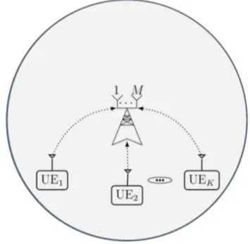
The evaluation of the MM system uplink is the focus of this study. The design and analysis of
MIMO systems includes one BS equipped with an array of M antennas that receive data from K
single-antenna users as illustrated in Fig. 1. Single-antenna users have the benefit of being
inexpensive, simple, and power-efficient, and yet each user still gets typically high throughput [6].
Fig. 1. Massive MIMO system uplink showing a BS with M antennas receiving data from K single-antenna users.
It is assumed that each user is uniformly distributed inside a single circular cell of radius R in which
a Monte Carlo simulation places the users to validate the study. In this case, the UE uplink is
associated with an average perceived SNR value. Then it is supposed that the BS is able to operate a
closed loop power control such that the UE varies the transmitted power in order to maintain the
received SNR by the BS constant.
In this study it is assumed that the transmitted data are modulated in both OFDM and FBMC. As
for the impact of the Doppler Effect on the results, it was demonstrated in [11] that it is not significant
for speeds below 130 km/h; thus, it is not applicable to this analysis since the users on the referred cell
are not moving which is a representative scenario for high density urban areas, where mobility is
always below the mentioned speed.
The elements of the M x K frequency response of the matrix-valued channel that connects the BS
antennas and user antennas are assumed as independent, identically distributed (i.i.d.), zero-mean
complex Gaussian and unit-variance random variables (i.i.d. Rayleigh) [12].
The MM setup considers K users communicating with the BS through Time Division Duplex
(TDD). According to this protocol, all the users in the cell first synchronously send uplink data
state information (CSI) to the users located in their cells. Then, the BS use the estimated CSI to detect
the uplink data [13]. In this way, all users in a cell can simultaneously use all subcarriers.
B. Perfect Channel State Information
In this study, the issues related to channel estimation are not considered, including the pilot
contamination problem. Thus, the present analysis assumes that perfect knowledge of CSI is available
at the BS. This information describes how a signal propagates from the transmitter to the receiver and
represents the combined effect of scattering, fading, and power decay with distance. The CSI makes it
possible to adapt transmissions to current channel conditions, which is crucial for achieving reliable
communication with high data rates in MIMO systems [14].
One of the main problems limiting the performance of an MM system is pilot contamination, which
is due to the limited number of possible orthogonal pilot sequences [13]. When considering that the
channel properties of a communication link are known, or in other words, assuming that the CSI is
accurately known at the transmitter and receiver, the pilot contamination problem becomes negligible.
The assumption of perfect CSI at the BS and the fact that the number of antennas is large enough in
MU-MIMO makes it possible to compare performances between this system and a SISO signal. In
fact, when fast fading and intracellular interference are not present, the MU-MIMO system is similar
to a SISO system [6]. In fact, according to [15] as the number of BS antennas grows without limit all
the effects of uncorrelated noise and fast fading disappear. This condition validates the proposed
approach.
C. FBMC Overview
The Filter Bank Multicarrier (FBMC) is a development of OFDM which focus on overcoming some
limitations while enabling higher throughput data rates. It is a form of multi-carrier modulation that is
being investigated to be applied in wireless and cellular systems to come. FBMC relies on dividing
the spectrum into multiple orthogonal sub-bands and applies a filter to each subcarrier individually.
Thus, with FBMC the side-lobes are much weaker and the inter-carrier interference (ICI) is by far less
critical than what is observed in OFDM [5]. In fact, the addition of redundant data in a Cyclic Prefix
(CP) in OFDM system addresses the problems caused by ICI as well.
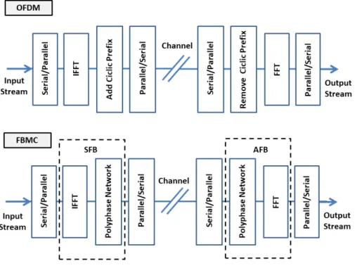
FBMC is a multicarrier modulation method in which a set of synthesis and analysis filters are
employed at the transmitter and receiver, respectively [16]. The filters used in the FBMC systems are
a set of bandpass filters. The block diagrams of OFDM and FBMC modulations are represented in
Fig. 2. This figure illustrates that in FBMC the Inverse Fast Fourier Transform (IFFT) plus CP
presented in the input of OFDM are replaced by a synthesis filter bank (SFB). In its turn, in the output
the CP plus Fast Fourier Transform (FFT) in an OFDM system are replaced by the analysis filter bank
Brazilian Microwave and Optoelectronics Society-SBMO received 30 Sept 2018; for review 05 Nov 2018; accepted 13 Nov 2018 Fig. 2. Block diagrams showing the differences in modulators for OFDM and FBMC.
FBMC gives a better bandwidth efficiency compared to OFDM because FBMC does not use the CP
extension; hence it has to attenuate the interferences within and close to the used frequency band
efficiently. Fig. 3 illustrates the difference in out-of-band (OOB) emissions which indicates that
FBMC has much better spectral properties compared to OFDM.
Fig. 3. FBMC exhibits a low OOB emission when compared to OFDM modulation.
subcarrier, which can be achieved by the polyphase network (PPN), meanwhile in the OFDM system
shows the rather strong side-lobes due to rectangular windowing [17]. In its turn, the PPN consists of
a set of digital filters that are responsible for the extra processing that makes it possible to not use the
CP and can be seen as an extension of an IFFT [18].
An important note about the FBMC signal is that in contrary to OFDM, the orthogonality is not
ensured for all the carriers, there is a different concept involved. In FBMC, each subcarrier is
individually filtered and orthogonality is required only in the sub-channel level, which means that it
requires orthogonality for the adjacent sub-channels only [18]. In fact, FBMC divides the transmission
channel associated with the given bandwidth into a number of sub-channels. In order to fully exploit
the channel bandwidth, the modulation in the sub-channels must adapt to the neighbor orthogonality
constraint and to deal with this issue, offset quadrature amplitude modulation (OQAM) is used for
that purpose.
The concept of OQAM consists in splitting, into consecutive symbols, the real and imaginary parts
of the quadrature amplitude modulation (QAM) symbol so that they are alternated in time [19]. For
that, the imaginary symbols suffer a delay of half the duration of the symbol with respect to the real
symbols, avoiding their simultaneous transmission. Ultimately, the combination of filter banks with
OQAM modulation leads to a superior throughput, without the need of a guard time or CP as in
OFDM. Thanks to the use of offset-QAM in FBMC, the interference is easily canceled at the receiver
by ignoring the part of the received symbol not carrying data [5].
In the comparison between OQAM and QAM for non-orthogonal waveforms, OQAM can offer
lower peak-to-average power ratio (PAPR), while smaller frame error rates (FERs) can be achieved
by QAM in rich multipath fading channels. Moreover, FBMC adopts linear convolution, instead of
circular convolution, to significantly reduce out-of-band (OOB) emission for the sake of robustness
against synchronization errors and to preserve its spectral properties [20].
The application of FBMC in MM channels has been recently studied in [21], in which its so-called
self-equalization property leading to a channel flattening effect was observed in the simulations.
According to this property, as the number of BS antennas increases, it results in a nearly equalized
gain across each subcarrier band and the effects of channel distortions like inter-symbol interference
(ISI) and ICI diminish as the number of BS antennas increases. In fact, the combination of FBMC and
MM can bring pivotal properties into the picture of 5G systems. Specifically, this combination is of a
great importance as not only the same spectrum is being utilized by all the users but it is also used in a
more efficient manner [22].
Finally, although the filter bank itself is slightly more complex than the respective element in
OFDM, from a conceptual point of view, the signal generation in FBMC-OQAM and windowed
OFDM requires basically the same operations. Therefore, FBMC-OQAM can reuse many hardware
Brazilian Microwave and Optoelectronics Society-SBMO received 30 Sept 2018; for review 05 Nov 2018; accepted 13 Nov 2018 III. SPECTRAL EFFICIENCY ANALYSIS
A. Evaluation of OFDM and FBMC under a SISO Signal
In [10], real-world testbed measurements at 2.5GHz that consist in comparing the FBMC and
OFDM techniques are presented. Under conditions that resemble an LTE SISO signal with 1.4MHz
bandwidth, it was demonstrated that FBMC has a higher throughput when compared to OFDM due to
the exclusion of the CP on FBMC.
Throughout that study, OFDM is compared to FBMC in terms of their spectral properties. To test
the attainable SEs, the modulation scheme per sub-carrier varies from 4-QAM to 64-QAM, being then
combined with block error-correcting codes having rates from 78/1024 to 948/1024. Monte Carlo
simulations are carried out and the Packet Error Rate (PER) is observed. The simulation can be seen
as an adaptive modulation system. For different SNRs applied, the transmission begins with the more
basic modulation, then the modulation-coding scheme is changed to the next, until a PER of 10-3 is
detected. This sets the attainable SE for that SNR. The results are illustrated in Fig. 4 along with the
theoretical bounds for Rayleigh fading extracted from the throughput presented in [10].
Fig. 4. Spectral Efficiency represented as a function of SNR in a SISO system for OFDM and FBMC.
TABLE I.BASIC SETTINGS UNDER SISOSIGNAL FOR OFDM AND FBMC
Parameter Value
Carrier Frequency 2.5GHz
Bandwidth 1.4MHz
Pilot Density 0.044
Subcarrier Spacing 15KHz
Subcarriers - FBMC 87
Subcarrier - OFDM 72
Cyclic Prefix - OFDM 4.76µs (210KHZ) Modulation – OFDM perfect CSI 4, 16, 64 QAM Modulation – FBMC perfect CSI 4, 16, 64 OQAM
One can observe that both modulated signals (OFDM and FBMC), even when considering perfect
CSI, are far from the Shannon information theory Limit capacity [9], which for a SISO system is
described as:
(1)
This is expected since the M-QAM modulations and the error correcting codes do not present a
Gaussian distribution. Taking these facts into account, those curses that do not follow equation (1),
but are represented in Fig. 4 (for instance: “OFDM perfect CSI” and “FBMC perfect CSI”) are
characterized from now on as SESISO(SNR). One can observe in Fig. 4 that SESISO is better for FBMC
as the SNR increases but it is almost the same as OFDM for low SNR values.
B. Spectral Efficiency Analysis in a Massive MIMO System Uplink
The SE for the MM system uplink in a single-cell environment is analyzed in [6]. An expression for
SE is introduced by employing linear detectors at the BS. The study considers a fading Rayleigh
MIMO channel for each subcarrier and also, that perfect CSI can be acquired at the BS. Considering a
Zero Forcing (ZF) detector at the BS, the system SE is approximated by [6]:
2 1
log 1 ( ) ,
K
zf k
k
SE M K pu
(2)where K is the number of UEs with a single antenna, M is the number of antennas at the BS, pu is the
UE transmitted power (considered the same for every user) and k is the large-scale fading for the k th
user. The expression (2) represents the lower bound on the achievable rate in terms of SE for the
linear receiver ZF in an uplink transmission, considering that the modulated signals are Gaussian
distributed.
Unlike in the time-invariant AWGN channel, capacity of a flat-fading channel in MIMO depends
on what is known about the time-varying channel at the transmitter and/or receiver. For instance, in
the absence of channel side information at the transmitter, the mutual information for all channel
_ log2 1 .
shannon SISO
Brazilian Microwave and Optoelectronics Society-SBMO received 30 Sept 2018; for review 05 Nov 2018; accepted 13 Nov 2018 realizations becomes constant for a large number of transmit and receive antennas [23]. Besides, as
shown in [12] the equation (2) is valid for SNR >> 1. The validity of this equation also depends on the
receiver knowing the downlink channel matrix, which the perfect CSI criterion corroborates.
Similarly, the Shannon capacity for a flat-fading MU-MIMO channel under favorable propagation
has the uplink transmission in a single-cell MM system given by [3]:
2 1
log 1 .
K
shannon k
k
SE Mpu
(3)In order to find k, this study assumes the same expression established by [6] in which the large
scale fading coefficient can be written as:
/
,k k
k o
d d
(4)where dk represents the distance between the BS and each UE; do represents the minimum allowed
distance between a user and the BS (in this study do =10m); is the path-loss exponent and finally, k
represents a log-normal distributed shadow fading variable described as follows:
10
10 log
k N(0,
shadow). (5)The cell radius varies to show how the perceived SNR is affected. To simulate dk the study
considers that the UE positions are random following a uniform distribution for the Cartesian
coordinates and inside a circular cell of radius R.
C. SE Analysis for FBMC-OQAM in a Massive MIMO System Uplink
Comparing (2) and the Shannon limit of (1), one observe that (M - K)puk is analogous to SNR per
user, once the modulated signal is considered Gaussian distributed. For the same reason, Mpuk is
analogous to SNR in (3). In summary, in order to preserve the results found in [10], it is necessary to
identify the SNR related to the MM system uplink and then, use these data to project the
performances for FBMC and OFDM in a different scenario.
Assuming this premise, the first step will be to extract the SE presented in Fig. 4, under a SISO
signal, instead of applying the log2 (1+SNR) relation. As a result, the process of transitioning the
analysis of the SISO signal to an MM system can be concluded and the intrinsic relationship between
SNR and SE found in SISO can be validated for the uplink of the MM system. From the equation (6),
the SNRMM in MM considers the M number of antennas in the BS, the length of the radius of the cell
and other factors related to the channel (represented by pu andβk).
.
MM k
SNR pu M (6)
In both (2) and (3), the cell SE is a sum of the K users SEs. By comparing the equations (2) and (3),
one can verify that they are similar and also, that the difference lies in how the signal combination in
When considering (3), as well as the data extracted from Fig. 4, the analysis represents the
maximum achievable SE for the uplink in MM, for both OFDM and FBMC. In the end, one can
modify the following parameters to reproduce this analysis: K, M and R.
The simulation goes as follows: K users are randomly placed in a cell of radius R, pu is set
according to the maximum allowed transmission power for a given standard for the UE, then all UE
SNRs are calculated and averaged.When considering an average SNR value for all the K users, it is
observed that in the transition from SISO to MM, the final value of SE in MM is directly proportional
to K. In other words, making SEsiso as the SE related to the SISO signal (given as a function of SNR as
shown in Fig. 4) and SE'cellbeing the SE for MM considering only the influence of having K users in
the system, the SE value for the uplink of the MM system extracted from a SISO signal, assuming an
average behavior, can be written as:
'cell siso( ).
SE K SE SNR (7)
To identify which SNR will be used, one has to verify how much the radius of the cell will affect
the perceived SNR value by the uplink system. As seen in the equation (3), the final value of SE in
MM holds a logarithmic relation with the M number of antennas in the BS, and that fact also occurs in
the transition from SISO to MM. Thus, it is necessary to characterize the influence of having more
antennas in the BS so that the calculation of SE in the MM system uplink as a whole is feasible.
Taking (7) into account and considering an average behavior, the SE value for the uplink of the
MM system extracted from a SISO signal can be written as:
( ).
MM siso MM
SE K SE SNR (8)
And ultimately, that can be represented by:
( ).
MM siso k
SE K SE pu M (9)
Even though the SESISO(SNR) function is unknown, its behaviour can be observed in Fig. 4. The
comparison between expression (9) and the Shannon limit equation represented by expression (3) is
due to the fact that both analyses are using the same SNR value. This means that by using this
approach, it will be possible to compare the maximum theoretical values and the maximum achievable
values for OFDM-QAM and FBMC-OQAM in an adaptive modulation system validated for
measurements.
IV. SIMULATION RESULTS
This section provides an explanation of how the MM system uplink was simulated and how the SE
for OFDM and FBMC had its performance evaluated. The main parameters used in the simulation are
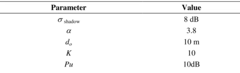
Brazilian Microwave and Optoelectronics Society-SBMO received 30 Sept 2018; for review 05 Nov 2018; accepted 13 Nov 2018 TABLE II.PARAMETERS OF THE MASSIVE MIMO SYSTEM UPLINK
Parameter Value
shadow 8 dB
3.8
do 10 m
K 10
Pu 10dB
As MM operates with a large number of BS antennas, typically in the order of hundreds or even
thousands, to serve a relatively small number of mobile terminals, the first scenario evaluates the
average SNRMM when M = 300, K=10 and R varies from 100m to 2500m. From the equation (4) one
can obverse that ultimately, the variableβk is determined by the position of the users in the cell, which
is affected directly by the cell radius and for consequence affects the SNRMM. Users are randomly and
uniformly positioned inside the cell and it is assumed that no user is closer to the BS than do.
Fig. 5. Average SNR in a MM system uplink as a function of the cell radius for M = 300 and K = 10.
As illustrated in Fig. 5, for a cell radius around 100m, the average SNR surpasses 40dB. Whereas,
Fig. 6. Spectral Efficiency evaluation in a MM system uplink for OFDM vs FBMC considering M = 300 and K = 10.
The analysis of an MM system uplink can be seen in Fig 6, in which the curves related to the SE
value for both modulations considering the cell radius going from 100 to 900m are illustrated. One
may notice that FBMC presents a significantly better SE for the range of cell sizes. In addition, there
is a point in which reducing the cell radius simply does not improve the SE, since it saturates
regarding the available modulation and coding schemes in Fig. 6. The main difference observed is
when an SE of 38bit/s/Hz is required, the cell radius can be doubled, from 350m to 700m when
switching from OFDM to FBMC. Both simulations show a much lower SE when compared to
theoretical bounds, showing that in a cell planning case, the presented results would lead to a more
realistic dimensioning.
The next test consists in evaluating the average SNR for a fixed cell radius of R=750m while
varying M from 50 to 1450 antennas (Fig. 7). This figure shows that the increase of SNRMM is stronger
at the beginning until the value gets closer to 20 dB. After that, it is required a much larger M to
impact the SNRMM. Fig.5 and Fig.7 can serve as flowcharts for dimensioning cells for 5G networks.
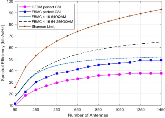
Correspondingly, Fig. 8 depicts the SE of an MM system uplink when M also goes from 50 to 1450
antennas and the cell radius is equal to 750m. The relative difference between SE in OFDM and
FBMC increases as M increases until M is roughly 850, then the difference becomes mainly the
contribution of the CP itself in the reduction of the OFDM SE and stabilize. The FBMC {4,16,…}
-OQAM are the theoretical bounds for Rayleigh fading considering an adaptive modulation structure.
Brazilian Microwave and Optoelectronics Society-SBMO received 30 Sept 2018; for review 05 Nov 2018; accepted 13 Nov 2018 Fig. 7. Average SNR in a MM system uplink as a function of the number of antennas at the BS for R = 750 and K = 10.
Still, by analyzing Fig. 8 one can observe that FBMC-OQAM is about 16% better spectral
efficiently than OFDM for 150 antennas whereas is about 30% better for 1450 antennas. Besides, the
OFDM requires almost 3 times more antennas considering an SE of 38 bits/s/Hz.
In this particular scenario, SE values above 40 bits/s/Hz are not achievable for OFDM while the
FMBC cannot reach SE values over 50 bits/s/Hz.
Finally, it is important to observe in Fig. 6 and Fig. 8 how far the curves from the simulations are in
relation to the theoretical limit. With this in mind, it is possible to assure that the theoretical limit
Fig. 8. Spectral Efficiency evaluation in a MM system uplink for OFDM vs FBMC considering R = 750 and K = 10.
V. CONCLUSION
The investigation of viable candidates for 5G network deployment is important because it tends to
pave the way for new solutions. In this paper, a method to analyze the SE for the MM system uplink
was proposed by taking the data throughput of a SISO system from simulation results that were
confirmed by measurements. By using this technique, it was possible to study the performance of
FBMC and OFDM modulations in a more realistic scenario.
The modulation and coding scheme are taken as the heart of the communication system. In the
tested scenarios, the performance analysis of SE revealed that the change from OFDM to
FBMC-OQAM guarantees an improvement of at least 25%, which is mainly due to the absence of the cyclic
prefix in FBMC. This difference becomes even more important when a limit SE is aimed. In some
cases, the number of antennas must be 3 times higher or the cell radius must be the half for OFDM
compared to FBMC.
Finally, it was demonstrated that the theoretical limits can be considered as overly optimistic, and
could not serve as a flowchart for practical implementations.
REFERENCES
[1] J. G. J. G. Andrews et al., “What will 5G be?,” IEEE J. Sel. Areas Commun., vol. 32, no. 6, pp. 1065–1082, 2014.
Brazilian Microwave and Optoelectronics Society-SBMO received 30 Sept 2018; for review 05 Nov 2018; accepted 13 Nov 2018 [3] K. N. R. S. V. Prasad, “Energy Efficiency in Massive MIMO-Based 5G Networks: Opportunities and Challenges,”
IEEE Wirel. Commun., pp. 2–10, 2016.
[4] J. Vihriala, N. Ermolova, E. Lahetkangas, O. Tirkkonen, and K. Pajukoski, “On the waveforms for 5G mobile broadband communications,” IEEE Veh. Technol. Conf., vol. 2015, 2015.
[5] F. Schaich and T. Wild, “Waveform contenders for 5G - OFDM vs. FBMC vs. UFMC,” ISCCSP 2014 - 2014 6th Int. Symp. Commun. Control Signal Process. Proc., pp. 457–460, 2014.
[6] H. Q. Ngo, E. G. Larsson, and T. L. Marzetta, “Energy and Spectral Efficiency of Very Large Multiuser MIMO Systems,” IEEE Trans. Commun., vol. 61, no. 4, pp. 1436–1449, 2013.
[7] L. Zhao, K. Li, K. Zheng, and M. O. Ahmad, “An analysis of the tradeoff between the energy and spectrum efficiencies in an uplink massive MIMO-OFDM system,” IEEE Trans. Circuits Syst. II Express Briefs, vol. 62, no. 3, pp. 291–295, 2015.
[8] C. He, B. Sheng, P. Zhu, X. You, and G. Y. Li, “Energy-and spectral-efficiency tradeoff for distributed antenna systems with proportional fairness,” IEEE J. Sel. Areas Commun., vol. 31, no. 5, pp. 894–902, 2013.
[9] G. J. Foschini and M. J. Gans, “On Limits of Wireless Communications in a Fading Environment when Using Multiple Antennas,” Wirel. Pers. Commun., vol. 6, no. 3, pp. 311–335, 1998.
[10] R. Nissel, S. Schwarz, and M. Rupp, “Filter Bank Multicarrier Modulation Schemes for Future Mobile Communications,” IEEE J. Sel. Areas Commun., vol. 35, no. 8, pp. 1768–1782, 2017.
[11] A. Bazin, B. Jahan, and M. Helard, “Impact of the Doppler effect on the capacity of massive MIMO uplink systems: OFDM versus FBMC/OQAM,” Proc. 24th Int. Conf. Telecommun. Intell. Every Form, ICT 2017, 2017.
[12] T. L. Marzetta, “Massive MIMO: An Introduction,” Bell Labs Tech. J., vol. 20, pp. 11–22, 2015.
[13] L. Lu, G. Y. Li, A. L. Swindlehurst, A. Ashikhmin, and R. Zhang, “An overview of massive MIMO: Benefits and challenges,” IEEE J. Sel. Top. Signal Process., vol. 8, no. 5, pp. 742–758, 2014.
[14] H. Q. Ngo, Hien Quoc Ngo Massive MIMO : Fundamentals and System Designs, vol. 1642, no. 1642. 2015.
[15] T. L. Marzetta, “Noncooperative cellular wireless with unlimited numbers of base station antennas,” IEEE Trans. Wirel. Commun., vol. 9, no. 11, pp. 3590–3600, 2010.
[16] A. Basheer and A. Habib, “Filter bank multi carrier based MIMO system for 5G wireless communication,” 2016 1st Int. Work. Link- Syst. Lev. Simulations, IWSLS 2016, pp. 52–57, 2016.
[17] A. N. Ibrahim and M. F. L. Abdullah, “The potential of FBMC over OFDM for the future 5G mobile communication technology,” AIP Conf. Proc., vol. 1883, 2017.
[18] M. Bellanger, “FBMC Physical Layer: A Primer,” PHYDYAS, January, pp. 1–31, 2010.
[19] M. Lopes, “MIMO designs for filter bank multicarrier and multiantenna systems based on OQAM,” Centre Tecnologic de Telecomunicacions de Catalunya, 2013.
[20] D. Zhang, M. Matthe, L. L. Mendes, and G. P. Fettweis, “A Study on the Link Level Performance of Advanced Multicarrier Waveforms under MIMO Wireless Communication Channels,” IEEE Trans. Wirel. Commun., vol. PP, no. 99, pp. 2350–2365, 2017.
[21] A. Farhang, N. Marchetti, and B. Farhang-Boroujeny, “Filter bank multicarrier for massive MIMO,” Signal Process. 5G Algorithms Implementations, pp. 67–89, 2017.
[22] A. Aminjavaheri, A. Farhang, L. E. Doyle, and B. Farhang-Boroujeny, “Prototype filter design for FBMC in massive MIMO channels,” IEEE Int. Conf. Commun., 2017.