VIBRATION CONTROL WITH
SHAPE-MEMORY ALLOYS
IN CIVIL ENGINEERING STRUCTURES
Filipe Pimentel Amarante dos Santos
Mestre em Engenharia de Estruturas
Disserta¸c˜ao apresentada `a Faculdade de Ciˆencias e
Tecnologia da Universidade Nova de Lisboa para obten¸c˜ao
do grau de Doutor em Engenharia Civil
Orientador: Professor Doutor Corneliu Cisma¸siu
J´
uri:
Presidente: Professor Doutor Manuel Am´erico Gon¸calves da Silva
Arguente: Professor Doutor ´
Alvaro Alberto de Matos Ferreira da Cunha
Arguente: Professor Doutor Lu´ıs Manuel Coelho Guerreiro
Vogal: Professor Doutor Ant´onio Jos´e Lu´ıs dos Reis
Vogal: Professor Doutor Jo˜ao Carlos Gomes Rocha de Almeida
“Copyright” Filipe Pimentel Amarante dos Santos, FCT/UNL e UNL
Acknowledgments
This dissertation would not have been accomplished without the support and assis-tance from many people in many different ways.
I would like to express my deepest and heartfelt recognition to my adviser, Prof. Corneliu Cisma¸siu. I cannot thank him enough for his priceless scientific teachings, for his invaluable guidance and commitment, for his inestimable encouragement, confidence and utmost support, and last but not the least, for his enormous gen-erosity and kind friendship, which have made this graduation experience so positive and so meaningful. To work with him was a great pleasure and a privilege.
I am truly and forever grateful to Prof. J. Pamies Teixeira for his incalculable help during the design and construction phases of the physical prototype. Without his inspired input and thoughtful dedication the interdisciplinary nature of this study could not have been achieved.
I would like to show my true appreciation to Prof. F. M. Br´as Fernandes, who first brought me into the shape-memory world and with whom I had so many fruitful and delightful discussions, and to K.K. Mahesh for his precious help during the DSC tests.
I would like to thank Prof. Fernando Coito for his availability and for his insightful explanations about modern control engineering.
I am also indebted to Prof. J. C. G. Rocha de Almeida and I profoundly thank him for his unconditional support in overcoming all the bureaucratic perils that have appeared along the way.
I thank Prof. M. Gon¸calves da Silva for his warm welcome to the Civil Enginnering Department and for his relentless efforts in providing me with the necessary logistic
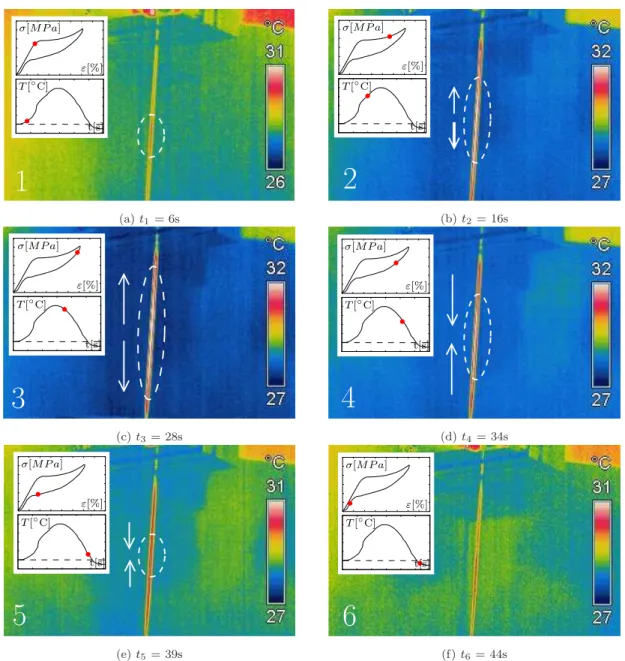
I kindly acknowledge Prof. F. Henriques for the use of the infrared camera, during the study of the transformation fronts.
I thank Prof. Ant´onio Reis for introducing me to scientific investigation, for inciting my natural curiosity in the pursuit of further knowledge and for motivating me to continue my academic studies. I am also grateful to him for the technical data regarding the S. Martinho viaduct.
To my colleagues and friends I thank for all the good disposition and support.
I specially would like to thank my good friend M´ario Silva for his priceless technical support with Linux, always managing to solve the innumerable helpless situations I found myself into during the coarse of this work. I also thank him and Jos´e Varandas for all the waves I had the pleasure of sharing with them and for all the laughter.
I thank my parents for all their love and everlasting devotion.
Finally, all my love goes to Inˆes and Afonso as they are the bright sunshine of my life.
Abstract
The superelastic behavior exhibited by shape-memory alloys shows a vast potential for technological applications in the field of seismic hazard mitigation, for civil engi-neering structures. Due to this property, the material is able to totally recover from large cyclic deformations, while developing a hysteretic loop. This is translated into a high inherent damping, combined with repeatable re-centering capabilities, two fundamental features of vibration control devices.
An extensive experimental program provides a valuable insight into the identification of the main variables influencing superelastic damping in Nitinol while exploring the feasibility and optimal behavior of SMAs when used in seismic vibration control.
The knowledge yielded from the experimental program, together with an extensive bibliographic research, allows for the development of an efficient numerical frame-work for the mathematical modeling of the complex thermo-mechanical behavior of SMAs. These models couple the mechanical and kinetic transformation constitutive laws with a heat balance equation describing the convective heat problem. The seis-mic behavior of a superelastic restraining bridge system is successfully simulated, being one of the most promising applications regarding the use of SMAs in civil engineering structures.
A small-scale physical prototype of a novel superelastic restraining device is built. The device is able to dissipate a considerable amount of energy, while minimizing a set of adverse effects, related with cyclic loading and aging effects, that hinder the dynamic performances of vibration control devices based on passive superelastic wires.
Resumo
O comportamento superel´astico desenvolvido pelas ligas com mem´oria de forma confere-lhes um vasto potencial no que diz respeito a aplica¸c˜oes tecnol´ogicas no dom´ınio do controlo de vibra¸c˜oes em estruturas de engenharia civil. Devido `a su-perelasticidade, o material ´e capaz de recuperar a sua forma original, ap´os ter sido submetido a grandes deforma¸c˜oes, desenvolvendo um comportamento hister´etico. Este comportamento traduz-se numa capacidade de amortecimento intr´ınseca que, conjuntamente com as elevadas capacidades de reposicionamento do material, con-stituem caracter´ısticas fundamentais para a efic´acia de um dispositivo de controlo de vibra¸c˜oes.
´
E apresentado um vasto programa experimental que contribui para a identifica¸c˜ao das principais var´aveis que influenciam o amortecimento superel´astico do Nitinol, numa tentativa de explorar e optimizar a possibilidade da aplica¸c˜ao de ligas com mem´oria de forma no controlo estrutural de vibra¸c˜oes.
´
E tamb´em apresentada uma ferramenta num´erica para a modela¸c˜ao matem´atica do complexo comportamento termo-mecˆanico das ligas com mem´oria de forma. Os modelos considerados fazem o acoplamento de leis constitutivas que traduzem o seu comportamento mecˆanico bem como a cin´etica das transforma¸c˜oes martens´ıticas, com uma equa¸c˜ao de balan¸co energ´etico. O comportamento s´ısmico de um disposi-tivo de reten¸c˜ao superel´astico para pontes ´e testado com sucesso, sendo que se trata de uma das mais promissoras utiliza¸c˜oes de elementos superel´asticos em estruturas de engenharia civil.
Finalmente, ´e apresentado um prot´otipo `a escala reduzida de um dispositivo su-perel´astico para o controlo de vibra¸c˜oes que, sendo capaz de dissipar uma quanti-dade apreci´avel de energia, permite minimizar uma s´erie de efeitos adversos ligados `a superelasticidade.
Contents
List of Figures xiv
List of Tables xxvii
1 Introduction 1
1.1 Problem Description . . . 1
1.2 Objectives and Scope . . . 3
1.3 Dissertation Outline . . . 4
List of Symbols and Abbreviations 1 2 SMAs in Vibration Control Devices 7 2.1 Introduction . . . 7
2.2 General aspects of Shape-Memory alloys . . . 8
2.2.1 Martensitic transformation . . . 8
2.2.2 Superelasticity . . . 11
2.2.3 Shape-Memory effect . . . 14
2.2.4 Internal friction . . . 16
2.3 Vibration control devices . . . 19
2.4.1 Bracing systems . . . 21
2.4.2 Base isolation system . . . 24
2.4.3 Bridge hinge restrainers . . . 25
2.4.4 Structural connections . . . 29
2.4.5 Applications in existing civil engineering structures . . . 31
2.5 Constraints of using shape-memory alloys . . . 36
2.6 Closure . . . 37
3 NiTi Shape-Memory Alloys 39 3.1 Introduction . . . 39
3.2 Characterization of Nitinol . . . 40
3.2.1 Microstructure . . . 40
3.2.2 Tensile properties . . . 42
3.2.3 Transformation temperatures . . . 44
3.2.4 Clausius-Clapeyron coefficient . . . 46
3.2.5 Influence of ambient temperature on damping . . . 48
3.2.6 Internal loops . . . 50
3.2.7 Influence of strain-amplitude on damping . . . 52
3.2.8 Self-heating on mechanical cycling . . . 54
3.2.9 Influence of strain-rate on damping . . . 57
3.2.10 Transformation fronts . . . 59
3.2.11 Cyclic properties . . . 61
3.2.13 Fatigue properties . . . 65
3.2.14 Strain-creep and stress-relaxation . . . 66
3.2.15 Aging effects . . . 68
3.3 Closure . . . 72
4 Constitutive Models for SMAs 75 4.1 Introduction . . . 75
4.2 Mechanical laws . . . 76
4.2.1 Simple serial model . . . 76
4.2.2 Voight scheme . . . 78
4.2.3 Reuss scheme . . . 79
4.3 Kinetic laws . . . 79
4.3.1 Linear transformation kinetic laws . . . 80
4.3.2 Exponential transformation kinetic laws . . . 81
4.4 Thermal effects . . . 83
4.5 Adopted constitutive models for SMAs . . . 87
4.6 Numerical implementation of the models . . . 88
4.6.1 Numerical implementation of the rate-independent constitu-tive model . . . 88
4.6.2 Algorithm for the rate-independent constitutive model . . . . 91
4.6.3 Numerical implementation of the rate-dependent constitutive model . . . 92
4.6.4 Algorithm for the rate-dependent constitutive model . . . 95
4.7.2 Dynamic tests . . . 102
4.8 Strain-rate analysis using the rate-dependent model . . . 107
4.9 Closure . . . 109
5 Modeling of SE Vibration Control Devices 111 5.1 Introduction . . . 111
5.2 Mathematical modeling of dynamical systems . . . 112
5.3 Pre-strain in superelastic wires . . . 113
5.4 Numerical implementation . . . 114
5.4.1 Algorithm to solve the equation of motion . . . 115
5.5 Numerical tests . . . 117
5.5.1 Vibration control device with SE wire . . . 117
5.5.2 Vibration control device with two pre-strained SE wires work-ing in phase opposition . . . 118
5.5.3 Vibration control device with two pre-strained SE wires and a re-centering element . . . 121
5.5.4 Influence of the ambient temperature on SE vibration control devices . . . 122
5.5.5 Influence of strain-rate on SE vibration control devices . . . . 123
5.5.6 Influence of strain-amplitude on SE vibration control devices . 125 5.5.7 Influence of the constitutive model on the modeling of SE vibration control devices . . . 126
5.6 SE restrainer cables in a viaduct . . . 129
5.6.2 Influence of the model on the seismic analysis . . . 132
5.6.3 Influence of the SE restraining area . . . 133
5.7 Closure . . . 135
6 Novel SE Device 141 6.1 Introduction . . . 141
6.2 Semi-active device under harmonic excitation . . . 142
6.2.1 Passive system with no pre-strain . . . 142
6.2.2 Passive system with pre-strain . . . 143
6.2.3 Semi-active system . . . 144
6.3 Semi-active device under seismic excitation . . . 153
6.4 Closure . . . 158
7 Prototype of the Novel SE Device 161 7.1 Introduction . . . 161
7.2 Building the prototype . . . 161
7.2.1 Moving-mass-module . . . 163
7.2.1.1 Force-sensors . . . 164
7.2.1.2 Displacement-sensor . . . 172
7.2.2 Linear actuators . . . 173
7.2.2.1 Electromechanical cylinder . . . 174
7.2.2.2 Servo-motor and servo-drive . . . 174
7.2.2.3 Mounting system and clamps . . . 175
7.3.1 General control of the servo-system . . . 178
7.3.1.1 Speed-control mode . . . 179
7.3.2 Stress control in a SE wire . . . 180
7.3.2.1 Proportional-plus-integral-plus-derivative (PID) con-troller . . . 180
7.3.2.2 Transient-response analysis . . . 182
7.3.2.3 Tuning of the PID controller . . . 184
7.3.2.4 Sinusoidal stress input (reference signal) . . . 188
7.3.3 Displacement control for dynamic tensile testing . . . 188
7.3.4 SE control system with one restraining element . . . 192
7.3.5 SE control system with two restraining elements . . . 196
7.4 Closure . . . 201
8 Summary, Conclusions and Future Work 203 8.1 Summary and conclusions . . . 203
8.2 Future Work . . . 207
A Modeling of control systems 213 A.1 Laplace Transformation . . . 213
A.1.1 Definition of the Laplace transformation . . . 213
A.1.2 Laplace transforms of several common functions . . . 214
A.1.2.1 Step function . . . 214
A.1.2.3 Pulse function . . . 216
A.1.2.4 Impulse function . . . 216
A.1.3 Laplace transforms properties . . . 218
A.1.3.1 Linearity . . . 218
A.1.3.2 Differentiation and integration . . . 219
A.2 Transfer function . . . 220
A.3 Control systems . . . 221
A.4 Basic control actions . . . 224
A.4.1 Proportional control . . . 224
A.4.2 Derivative control . . . 224
A.4.3 Integral control . . . 225
A.4.4 Proportional-plus-integral-plus-derivative control . . . 225
A.4.5 Ziegler-Nichols tuning of PID controlers . . . 226
Appendix 212 B Implementation of control systems 229 B.1 TTL signal . . . 229
B.2 Position-control . . . 230
B.3 Servo-drive specifications . . . 231
C Virtual instruments 235 C.1 Control of the stress level in a SE wire VI . . . 235
C.2 Displacement control for dynamic tensile testing . . . 238
Bibliography 247
List of Figures
2.1 Schematic diagram of martensitic transformations (after Otsuka and Wayman [124]). . . 10
2.2 Typical uniaxial stress-temperature phase diagram of SMA material. Transformation strips are the unshaded regions (after Bekker and Brinson [23]). . . 10
2.3 Generic stress-strain response of a SMA above Af (adapted from
Shaw and Kyriakides [?]). . . 12
2.4 Mechanism of superelasticity (after Otsuka and Wayman [124]). . . . 13
2.5 Isothermal path on phase diagram and correspondent hysteresis. . . . 13
2.6 Generic stress-strain response of a SMA below Mf (adapted from
Shaw and Kyriakides [?]). . . 15
2.7 Mechanism of shape-memory effect (after Otsuka and Wayman [124]). 15
2.8 Shape-memory and superelastic sequence. Three dimensional stress, strain and temperature diagram. . . 16
2.9 Definition of energy dissipatedED in a superelastic loading cycle and
maximum strain energy ES0. . . 17
2.10 Small-scale steel framed prototype with SMA braces (adapted from
Boroscheck et al. [27]). . . 22
2.11 SMA-based energy dissipating and re-centering brace (adapted from
Dolce et al. [53]). . . 23
2.13 Configuration of elastomeric bearings, friction-pendulum bearings, SE austenitic wires and magnetorheological dampers. Low-friction
wheels for SMA wire installation (adapted from Shooket al. [149]). . 25
2.14 Unseating of bridge at in-span hinge during an earthquake. . . 26
2.15 Unseating of bridge at in-span hinge during the 1994 Northridge earthquake for an existing bridge and a bridge retrofit with
tradi-tional steel restrainer cables (adapted from Johnson et al. [82]). . . . 27
2.16 Restraining solution with SMA elements in a multi-span simply sup-ported bridge. . . 27
2.17 Schematic of the test setup and SMA restrainer cable (adapted from
Johnsonet al. [82]). . . 28
2.18 SMA restrainer test setup (adapted from Johnson et al. [82]). . . 28
2.19 Schematic of the test setup and SMA restrainer cable. Adapted from
Padgett et al. [127]. . . 30
2.20 SMA restrainer test setup (adapted from Padgett et al.[127]). . . 31
2.21 Schematic of the SMA-based connection test setup (adapted from Ocel et al. [117]). . . 31
2.22 SMA-based full-scale connection test setup (adapted from Ocel et
al.[117]). . . 32
2.23 Reinforcement details of beam-column element with coupler
(dimen-sions in mm) (adapted from Alam et al. [5]). . . 32
2.24 Basilica of St. Francis of Assisi in Italy (adapted from [43, 108]). . . . 33
2.25 St. Feliciano Cathedral in Italy (adapted from [35, 108]). . . 34
2.27 Bridge carrying Sherman Road over US-31, Michigan, USA (adapted from [84, 123]). . . 36
3.1 Austenite unit cell with B2 structure (adapted from[167]). . . 41
3.2 Schematic view of the B2 →B19’ transformation (adapted from[167]). 41
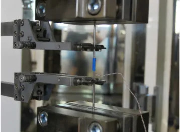
3.3 Zwick/Roell Z050 testing machine. Gripping apparatus for tensile test. 42
3.4 Stress-strain response of Nitinol wires during uniaxial tensile tests. . . 43
3.5 Stress-strain response during ultimate strength test. . . 44
3.6 Schematic illustration of a DSC. Variation in strain during heating and cooling under constant stress. . . 45
3.7 SETARAM-DSC92 thermal analyzer. General view. . . 46
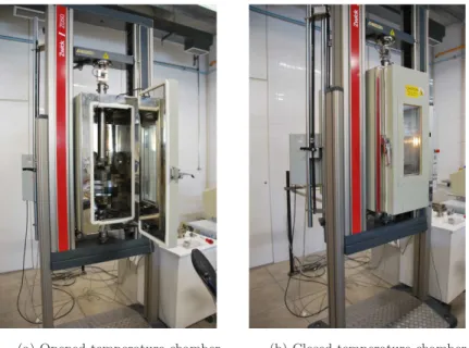
3.8 Temperature controled chamber during the tensile tests. General views. 47
3.9 Temperature dependence of the stress induced martensitic transfor-mation in a NiTi wire. . . 47
3.10 Variation of ambient temperature. Phase diagram path and corre-spondent isothermal hysteresis. . . 48
3.11 Influence of ambient temperature on damping. . . 50
3.12 Strain time-histories for internal loop testing in a SE Nitinol wire sample. . . 51
3.13 Stress-strain diagrams ( ˙ε = 0.02%/s). . . 51
3.14 Variation of strain-amplitude. Phase diagram path and correspondent isothermal hysteresis. . . 53
3.15 Influence of strain-amplitude on damping. . . 54
3.16 Detail of the thermocouple placed in the SE wire. . . 55
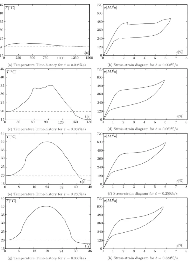
3.17 Self heating on mechanical cycling for different strain-rates (T0 =
20◦
3.19 Influence of strain-rate on the equivalent viscous damping. . . 59
3.20 FLIR ThermaCAM B4. . . 59
3.21 Temperature patterns within the SE wire specimen, during the
loading-unloading tensile test ( ˙ε = 0.250%/s). . . 60
3.22 Experimental cyclic tensile tests. Stress-strain diagrams. . . 62
3.23 Effects of SE cycling. . . 63
3.24 Experimental cyclic tensile tests. Temperature time-history. . . 64
3.25 Dissipated energy versus the number of cycles at failure [111]. . . 66
3.26 Strain-creep and strain-recovery. Phase diagram path and correspon-dent hysteresis. . . 67
3.27 Stress-relaxation and stress-recovery. Phase diagram path and corre-spondent hysteresis. . . 68
3.28 Aging under load in the parent phase. Phase diagram path and cor-respondent hysteresis. . . 69
3.29 Aging under constant stress in the coexistence zone. Phase diagram path and correspondent hysteresis. . . 70
3.30 Aging under constant strain in the coexistence zone. Phase diagram path and correspondent hysteresis. . . 71
4.1 Mechanical models for SMAs: (a) Simple serial model; (b) Voight
scheme; (c) Reuss scheme. . . 77
4.2 Superelastic stress-temperature phase plane diagram. Forward (A→
M) and inverse (M →A) transformations. . . 80
4.3 Cylindrical Nitinol wire surrounded by air. . . 84
4.5 Computation of ∆Wn. . . 94
4.6 Computation of the poligonal area. . . 98
4.7 Rate-independent numerical model vs. experimental data: quasi-static loading. . . 101
4.8 Rate-dependent numerical model vs. experimental data: quasi-static loading. . . 101
4.9 Rate-dependent numerical model vs. experimental data at
tempera-ture T0 = 20◦C, for increasing strain-rate ( ˙ε). . . 104
4.10 Rate-dependent numerical model vs. bibliographic experimental data [51] for two strain-rates (0.28%/s and 1.40%/s) and four temperatures (10,
20, 30 and 40◦
C). . . 105
4.11 Rate-dependent numerical model vs. bibliographic experimental data [51]: equivalent viscous damping. . . 106
4.12 Analysis of strain-rate variation at 20◦
C ambient temperature. . . 108
4.13 Strain-rate influence on the equivalent viscous damping. . . 108
5.1 SDOF oscillator, with a SE SMA wire acting as restoring element. . . 113
5.2 Difference between a pre-strained SE wire and a non-pre-strained SE wire subjected to the same strain amplitude: stress-strain relations. . 114
5.3 Average acceleration method, (γ = 1/2, β = 1/4). . . 114
5.4 Single SE wire (T = 20◦
C, f = 2 Hz). . . 118
5.5 SDOF oscillator, with two pre-tensioned wires working in phase op-position. . . 119
5.6 Behavior of SE1 and SE2 during generic harmonic cycles. . . 119
5.7 Two pre-strained wires working in phase opposition (T = 20◦
C, f = 2 Hz).120
5.10 Influence of the ambient temperature on hysteretic cycles. . . 124
5.11 Influence of the strain-rate on hysteretic cycles. . . 125
5.12 Influence of the strain-amplitude on hysteretic cycles. . . 126
5.13 Two pre-tensioned SMA SE wires with re-centering element: (a) dis-placement time-history; (b) stress time-history; (c) phase-plane; (d) force-displacement. . . 128
5.14 Superelastic restrainer cables at bridge’s supports. . . 129
5.15 S˜ao Martinho railway viaduct: Mid-span cross section, SMA passive control device location and finite element model. . . 130
5.16 Generated accelerograms. . . 131
5.17 Longitudinal displacement time-history for free and controlled systems.132
5.18 Longitudinal velocity time-history for free and controlled systems. . . 133
5.19 Longitudinal acceleration time-history for free and controlled systems. 134
5.20 Force in the vibration control device time-history. . . 135
5.21 Time history of the longitudinal displacement of the viaduct deck. . . 136
5.22 Longitudinal displacement and acceleration of the deck in function of
the SE restraining area. . . 137
5.23 Longitudinal velocity of the deck and SE force in function of the SE restraining area. . . 138
5.24 Parametric curves in function of the SE restraining area. . . 139
6.1 Passive system with no pre-strain subjected to an harmonic load.
6.2 Passive system with pre-strain subjected to an harmonic load. Strain and displacement time histories. . . 143
6.3 Generic functional scheme of the passive and the semi-active systems:
SE wires (SE1 and SE2), supports (S1 and S2) and markers (M1 and
M2). . . 145
6.4 Block diagram of the on-off control system. . . 146
6.5 Strain level time-history for the SE wire control system. . . 147
6.6 Semi-active system subjected to an harmonic load. Strain and dis-placement time-histories. . . 147
6.7 Semi-active system subjected to an harmonic load of higher ampli-tude. Strain and displacement time histories. . . 148
6.8 Semi-active system subjected to an harmonic load of higher
ampli-tude. Strain-stress hysteretic response for SE1 and SE2. . . 149
6.9 Semi-active system subjected to an harmonic load of higher ampli-tude. Stress time history and force-displacement hysteretic response. . 149
6.10 Re-centering of the semi-active system subjected to an harmonic load. Strain and displacement time-histories. . . 150
6.11 Relative displacements of the SE wires at the supports. . . 151
6.12 General behavior of the proposed semi-active control system. . . 152
6.13 El Centro and Kobe earthquakes: PEER Strong Motion Database records [126]. . . 154
6.14 Response of the structure toEl Centroearthquake: displacement and
acceleration time history for the free and controlled structure. . . 155
6.15 Response of the structure toEl Centroearthquake: strain time history
in the SE wires of the controlled structure. . . 156
6.16 Response of the structure to Kobe earthquake: displacement and
7.1 Simple supported bridge with a SE restraining system. . . 162
7.2 General design concept for the physical prototype. . . 163
7.3 Moving-mass-module. Design phase. . . 165
7.4 Concept design of the force-sensor. . . 165
7.5 Schematics of the force-sensor. Full-bridge circuit diagram. . . 166
7.6 ANSYS results: plot of the strain field along the longitudinal direction
of plate . . . 168
7.7 ANSYS results: plot of the displacement along the direction of the
SE wire . . . 168
7.8 Force-sensor. General views. . . 169
7.9 Force-sensor block diagram. . . 170
7.10 Force-sensor VI front panel. . . 170
7.11 Calibration curve. . . 171
7.12 Moving-mass-module. General views. . . 172
7.13 Dimensional drawing of the Solartron DC25 LVDT displacement trans-ducer (adapted from [7]). . . 173
7.14 Position of the LVDT. . . 173
7.15 Dimensional drawing of the electromechanical cylinder (adapted from [28]).174
7.16 Dimensional drawing of the Omron-Yaskawa servo-motor (adapted from [120]). . . 175
7.17 Design concept of the side-driven mounting system, with a belt side drive. . . 176
7.19 Simplified external input signal circuits for the servosystem control modes, with corresponding connector pin (adapted from [120]). . . 179
7.20 Block diagram of the speed-control VI. . . 180
7.21 Experimental setup to control the stress level in a SE wire. . . 180
7.22 Block diagram of the stress control system. . . 181
7.23 PID.vi [113]. . . 182
7.24 Typical unit-step reponse of a control system . . . 183
7.25 Closed loop tuning procedure: Ultimate gain. . . 185
7.26 Plot of PV vs time, for three values ofKp (Ti =∞, Td = 0). . . 186
7.27 Plot of PV vs time, for three values ofTi(s) (Kp = 0.12 , Td = 0). . . 187
7.28 Plot of PV vs time, for three values ofTd(s) (Kp = 0.18 ,Ti = 0.35). . 187
7.29 Harmonic reference stress signals: reference signal vs. output signal. . 189
7.30 Experimental setup for the dynamic tensile test. . . 190
7.31 Displacement control loop for dynamic tensile testing. . . 190
7.32 Dynamic tensile tests (T0 = 22◦C): Stress-strain diagrams and
tem-perature time-histories. . . 191
7.33 Influence of high strain-rates on the equivalent viscous damping. . . . 192
7.34 Experimental setup of the vibration control system with one restrain-ing element. . . 193
7.35 Block diagram of the SE vibration control system with one restraining element. . . 194
7.36 Force time-history. . . 195
7.39 Block diagram of the SE vibration control system with two restraining elements. . . 197
7.40 Force-displacement diagrams. . . 198
7.41 Force-displacement diagrams. . . 199
7.42 Force time-history (SE1). . . 200
7.43 Force-displacement diagram evolution. . . 200
7.44 Acceleration time-history. . . 201
8.1 Retractor locking mechanism. . . 208
8.2 Load limiter (adapted from [19]). . . 209
8.3 Force-displacement diagrams. . . 209
8.4 Schematics of a retractor with SE torsion bar. . . 210
8.5 Schematics of a retractor with MR brake. . . 211
A.1 Step function . . . 214
A.2 Ramp function . . . 215
A.3 Pulse function . . . 216
A.4 Impulse function . . . 217
A.5 Basic control system . . . 222
A.6 Summing and branch points . . . 222
A.7 Block diagram of a closed-loop system . . . 223
A.8 Simplified block diagram of a closed-loop system . . . 223
A.10 S-shaped response curve. . . 227
B.1 Specifications of a TTL compatible signal (adapted from [114]). . . . 229
B.2 Pulse train. . . 231
B.3 Block diagram of the position-control VI. . . 231
B.4 Dimensional drawing of the Omron-Yaskawa servo-drive (mm) [119]. . 232
B.5 General block diagram of the servo system (adapted from [121]). . . . 232
C.1 Front panel of the stress control VI. . . 235
C.2 Block diagram of the stress control VI. . . 236
C.3 Case structure 1: signal generation (true-false). . . 237
C.4 Case structure 2: measurement file (true-false). . . 237
C.5 Case structure 3: power (true-false). . . 237
C.6 Front panel of the displacement control VI for dynamic tensile testing. 238
C.7 Block diagram of the displacement control VI for dynamic tensile testing. . . 239
C.8 Case structure 1: stress signal generation (true-false). . . 240
C.9 Case structure 2: measurement file (true-false). . . 240
C.10 Case structure 3: power (true-false). . . 240
C.11 Case structure 4: displacement signal generation (true-false). . . 240
C.12 Front panel of SE vibration control system with one restraining element.241
C.13 Block diagram of the SE vibration control system with one restraining element (partial). . . 242
C.14 Case structure 1: PID threshold high (true). . . 243
C.17 Block diagram of the SE vibration control system with two restraining
elements (partial). . . 245
C.18 Case structure 1: PID threshold high (Servodrive 1) (true). . . 246
C.19 Case structure 2: PID threshold low (Servodrive 1) (false). . . 246
C.20 Case structure 3: PID threshold high (Servodrive 2) (true). . . 246
List of Tables
3.1 Properties of structural steel and Nitinol (reference values from [102]). 40
4.1 Parameters for the quasi-static tensile tests. . . 100
4.2 Parameters for the dynamic tensile tests. . . 102
4.3 Parameters for the dynamic tensile tests at higher strain-rates. . . 103
5.1 Parameters for the constitutive models. . . 127
7.1 Mass of the MMM elements. . . 164
7.2 Calibration of the force-sensor. . . 171
7.3 Ziegler-Nichols tuning rule based on a stability boundary (Decay ratio of 0.25). . . 185
A.1 Ziegler-Nichols tuning rule based on step response (Decay ratio of 0.25).227
Chapter 1
Introduction
1.1
Problem Description
Shape-memory alloys (SMAs) are a unique class of metallic alloys that show two out-standing properties: the shape-memory effect and superelasticity. These properties derive from the ability of these materials to develop a diffusionless phase transfor-mation in solids called martensitic transfortransfor-mation. The shape-memory effect allows the material to recover its original geometry during heating, after being deformed. Superelasticity enables the material to withstand large cyclic deformations, without residual strains, while developing a hysteretic loop. The formation of this hysteretic loop translates into the ability of the material to dissipate energy. Due to this high inherent damping, combined with repeatable re-centering capabilities and relatively high strength properties, SMAs have been progressively introduced in new techno-logical applications related with energy dissipation in civil engineering structural design.
For the time being, most of the applications regarding the use of SMAs in civil en-gineering structures are linked with the seismic resistance enhancement of cultural heritage structures [35, 43, 77]. However, several studies have already proved the effectiveness of SMAs in a wide range of vibration control devices, i.e. bracing sys-tems [27, 53, 103, 177], base isolation syssys-tems [42, 149, 174], bridge hinge restraining systems [8, 46, 82, 127] and structural connections [117, 157].
Although these studies have clearly demonstrated the vast potential of SMAs in
passive vibration control, they are affected by a set of undesirable effects that have an adverse impact on the dynamic performances of vibration mitigation devices based on superelastic (SE) kernel components. These effects comprise the high dependence of these materials towards strain-rate, strain-amplitude and temperature [51, 55, 78, 109, 124, 131, 132, 135, 137, 139, 143, 169].
When passing from quasi-static conditions to dynamic ones, significant changes
oc-cur in the shape and size of the SE hysteresis [91, 94, ?], affecting the damping
capabilities of the SMA dissipating element. One of the problems hindering the application of SMAs in vibration control systems is that the total area enclosed by a SE cycle, representing the dissipated energy, tends to decrease as the frequency of the dynamic loading increases [51, 62, 135].
Strain-amplitude also plays an important role in the hysteretic damping mechanism, since the total amount of dissipated energy during a SE cycle directly depends on the extent of the martensitic transformation [62]. This is why some of the most promising applications regarding SMAs in structural vibration control comprise pre-strained SE elements [51, 177]. This enables higher martensite ratios during the dynamic solicitation and, hence, higher damping. However, time-dependent effects like stress relaxation in pre-strained SE specimens have been identified [78], and need to be conveniently controlled in order for the pre-strain to remain effective during service.
Civil engineering structures have to endure important temperature variations. Like other structural components, SE vibration control devices are highly influenced by ambient temperature. This relation is translated through a phase-plane diagram which enables the characterization of the stresses that induce the martensitic trans-formations in a SE specimen, for a given temperature [131]. As these critical stresses increase with temperature, there is a temperature threshold above which the SE damping effect may be compromised, for a given dynamic excitation. It is therefore necessary to clearly establish the temperature range within which a SE vibration control mechanism can still perform competitively.
1.2. OBJECTIVES AND SCOPE 3
stabilization of the SE hysteresis. This causes the net strain produced by a given structural oscillation to be reduced, decreasing the energy dissipation capabilities of the material. This effect may be controlled by an initial training procedure, or by limiting the stress levels during the dynamic loading within a narrower SE window [107, 111].
These effects may constitute an important setback to the application of SMAs in structural vibration control.
1.2
Objectives and Scope
The main objective of this dissertation is the material characterization of SE NiTi while exploring the feasibility and optimal behavior of SMAs when used in structural vibration control.
A set of parametric studies comprising experimental uniaxial tensile tests in SE NiTi wires, with various strain-rates, strain-amplitudes and ambient temperatures are performed, aiming to provide a valuable insight to the behavior of SMAs, and assess their adequacy to seismic vibration control in civil engineering structures. The cyclic behavior of NiTi wires is also investigated through an experimental ap-proach, addressing the effects of cycling on cumulative creep, critical stress to induce martensite and hysteretic width.
A control strategy aiming for the attenuation or suppression of the undesirable ef-fects affecting SMAs, which have an adverse impact on their dynamic performances, is developed. This control strategy is first implemented numerically to assess its performance in structural vibration control. Once validated, the control strategy is implemented in a small-scale prototype, reproducing a SE bridge restraining system. This prototype is subjected to various dynamic actions including the ones produced by a reduced shaking table.
1.3
Dissertation Outline
The content of the dissertation is organized into the following seven chapters:
Chapter 2 General introduction to SMAs, including a detailed description of the martensitic transformation which is responsible for the superelasticity and shape-memory effect in SMAs. Analysis of the SE energy dissipation mech-anism and its application in vibration control devices. Bibliographic survey regarding seismic hazard mitigation devices based in SE kernel elements.
Chapter 3 Analysis of the austenitic and martensitic crystallographic phases in Nitinol. Description of an extensive experimental program regarding the char-acterization of Nitinol, including temperature-controlled cyclic tensile tests, differential scanning calorimetry and infrared thermo-imaging. Discussion of the results obtained during the experimental procedures.
Chapter 4 Study of constitutive models for the mathematical modeling of SMAs and corresponding governing laws, coupling the mechanical properties and the transformation kinetics. Analysis of the convective heat transfer problem. Numerical implementation and subsequent assessment and comparison of the performance of the considered constitutive models.
1.3. DISSERTATION OUTLINE 5
Chapter 6 Numerical implementation of a semi-active control strategy aiming to attenuate or suppress the undesirable effects affecting SMAs, which have an adverse impact on their dynamic performances. Description of the proposed vibration mitigation device and analysis of the results yielded by the numerical tests.
Chapter 7 Analysis of a small-scale prototype for the simulation of a SE based bridge restraining system. Description of the proportional-plus-integral-plus-derivative (PID) algorithm used to control the mechanism. Discussion of the experimental results.
Chapter 2
Shape-Memory Alloys in
Vibration Control Devices
2.1
Introduction
The emphasis which is currently given to energy dissipation in civil engineering struc-tural design makes materials which are able to reduce vibrations increasingly more appealing. The desired features of high strength, stiffness and tolerance to adverse environments are, for most materials, incompatible with high damping capabilities. Although viscoelastic materials are able to exhibit high damping capabilities, they often show insufficient strength. In the last couple of years, a set of high damping metallic alloys, combining high inherent damping with relatively high strength prop-erties, have been progressively introduced in new technological applications. They
are called Shape-Memory Alloys. Two of their most important properties are the so
called shape-memory effect and superelasticity.
The shape-memory effect is a unique property of certain alloys that exhibit marten-sitic transformations, that enables the material to recover its original shape, after being deformed upon heating to a critical temperature. Superelasticity is associated with large nonlinear recoverable strains (up to 8%) during a mechanical cycle of loading and unloading [141]. Associated with the discovery of the superelasticity is
the Swedish physicist Arne ¨Olander, in the year of 1932, when he first encountered
the SE behavior using an AuCd alloy [124]. In 1938, Greninger and Moorandian
observed the disappearance and reappearance of a martensitic crystal structure by increasing and decreasing the temperature of a CuZn alloy [66]. The thermoelastic properties of the martensitic crystal phase of an AuCd alloy were widely reported by Kurdjumov and Khandros (1949) [86], and Chang and Read (1951) [37]. In the 1960s, Buehler and Wiley discovered the NiTi alloys, while working at the Naval Ordnance Laboratory (NOL). The NOL, now disestablished, was formerly located in White Oak, Maryland and was the site of considerable work that had practi-cal impact upon world technology. As a tribute to their workplace, they named this family of alloys Nitinol [71]. While the potential applications for Nitinol were realized immediately, practical efforts to commercialize the alloy didn’t take place until a decade later. This delay was largely due to the extraordinary difficulty in melting, processing and machining the alloy, technological processes that weren’t really overcome until the 1990s, when finally these practical difficulties began to be resolved [71].
Shape-memory alloys and other types of smart materials (i.e. piezoelectric materials, magnetorheologic fluids and so on) are being progressively introduced in lectures of engineering courses. Also, in the last years, SMAs have been the object of various innovative studies and industrial applications [8, 11, 25, 27, 42, 46, 53, 70, 82, 95,
97, 103, 112, 117, 125, 127, ?, 149, 157, 174, 177, 178].
2.2
General aspects of Shape-Memory alloys
2.2.1
Martensitic transformation
2.2. GENERAL ASPECTS OF SHAPE-MEMORY ALLOYS 9
during the phase transformation [131].
An ideal crystal is constructed by the infinite repetition in space of identical struc-tural units. The structure of all crystals is described in terms of a lattice, which is a regular periodic arrangement of points in space, with a group of atoms attached to each lattice point. One important feature of crystal structures is symmetry. Some lattices possess a large measure of symmetry, whilst others are symmetric in a much less extent. Since the martensite has lower symmetry than austenite, many variants can be formed from the same parent phase [124].
During the transformation from the high-temperature phase to the low-temperature phase, these martensitic variants are formed in a twinned pattern, in which the atoms achieve displacements with mirror symmetry. This occurs since the crystal lattice strives to achieve minimal potential energy states for a given temperature [141].
While most materials deform by slip or dislocation motion, martensite responds to stress by changing the orientation of its crystal lattice trough movement of the twin boundaries to the most accommodating variant to the applied stress [141]. By applying a certain level of unidirectional stress on a martensite specimen, one can
cause most of the martensite to tiltin the same direction, causing the detwinning of
crystal structure [71]; see Figure 2.1.
Stress and temperature have large influence on martensitic transformations. Such transformations can be either induced by heating (or cooling) or by stressing. The stress-temperature phase diagram is of the utmost importance in order to compre-hend the process of martensite transformation in SMA materials. As illustrated in Figure 2.2, the transformation develops across the strips [A],[M],[d] and [t], when a
given point (T, σ), representing the local state of the system moves across a strip in
the direction of the transformation, i.e., from the starting boundary to the finishing
boundary, as indicated by the director vectors ni (i = A, M, d, t) [23].
The phase diagram is divided into four major regions:
- Md region: only detwinned martensite can exist;
- A region: only austenite can exist;
- Mt,d region: both twinned and detwinned martensite can co-exist;
Martensite (twinned)
detwinning Heating Cooling
(parent phase) Austenite
Martensite (detwinned)
Deformation
H ea
ting
Temperature
Figure 2.1: Schematic diagram of martensitic transformations (after Otsuka and Wayman [124]).
Af As
Ms
M
t,dM
dn
dn
A[
M
]
[
t
]
n
tM
t,dA
Mf
[
d
]
n
M[
A
]
A
(T)(σ)
2.2. GENERAL ASPECTS OF SHAPE-MEMORY ALLOYS 11
In the stress-free state, a SMA is characterized by four transformation temperatures:
Ms andMf during cooling and AsandAf during heating. The first two (withMs >
Mf) indicate the temperatures at which the forward transformation starts and
fin-ishes, respectively. The last two (with As < Af) are the temperatures at which the
inverse transformation starts and finishes, Af being the temperature above which
the martensite becomes completely unstable [124]. Another important temperature
value is Md, which is an upper temperature limit above which martensite cannot
be stress-induced [55], because of the stability attained by austenite [109]. These transformation temperatures depend mainly on the alloy’s composition and process-ing [131].
2.2.2
Superelasticity
A generic stress-strain response of a SE wire is shown in Figure 2.3. When an unidirectional stress is applied to an austenitic specimen, within a temperature range
betweenAf andMd(Md> Af), an elastic distortion of the austenitic lattice starts to
occur (o-a). There is a critical value (a) whereupon austenite becomes unstable and
a transformation from austenite to stress-induced martensite (SIM) takes place; see
Figure 2.4. As the deformation proceeds the stress remains almost constant until the
material is fully transformed (a-b). During this part of the response the two phases
coexist. Upon stress removal, the elastic unloading of the detwinned martensite
(b-c’) takes place. Since martensite becomes unstable below a critical stress (c’)
a reverse transformation occurs as the unloading process continues. Detwinned martensite reverts back to austenite, at a lower stress plateau than during loading (c’-d’). When the material is fully transformed to the parent phase (d’) further unloading will follow the initial loading path, with full recovery of the deformation.
A hysteretic effect is hence produced. If the temperature is greater than Af, the
strain attained during loading is completely recovered at the end of the unloading. This process is translated by an energy-absorption capacity with zero residual strain,
called superelasticity. If the temperature is less thanAf, only a part of stress induced
martensite re-transforms into austenite. A residual strain is then found at the end
of the unloading, which can be recovered by heating above Af. This phenomenon
is generally referred to as partial superelasticity [60].
has transformed into martensite. Further straining requires the elastic loading of
the detwinned martensite (b-c). At point (c) the stress is high enough to cause
the slipping of the martensite lattices, as permanent deformation starts and the
tangent modulus of the material begins to decay (c-d). At an even higher stress
level, a second region of relatively low modulus starts (d-e’) which, under persistent
deformation, would cause the failure of the specimen.
If the material is unloaded above point (c), some sockets of the material transform
back into austenite, but an important residual deformation would be present.
of austenite Elastic deformation
Elastic deformation martensiteof detwinned (Slipped martensite)
Plastic deformation
Elastic deformation of detwinned martensite Forward transformation
c’ Stress
o a
e’
Unloading d
c
b
e Strain
d’ Inverse transformation Residual strain
Failure
Figure 2.3: Generic stress-strain response of a SMA above Af (adapted from Shaw
and Kyriakides [?]).
Since the martensitic transformation involves latent heat (enthalpy of transforma-tion), energy is absorbed into the material, or released to the surrounding environ-ment, depending on the direction of the transformation. The forward,
austenite-to-martensite (A→M) transformation is exothermic and the reverse
martensite-to-austenite (M→A) transformation is endothermic [61, 131].
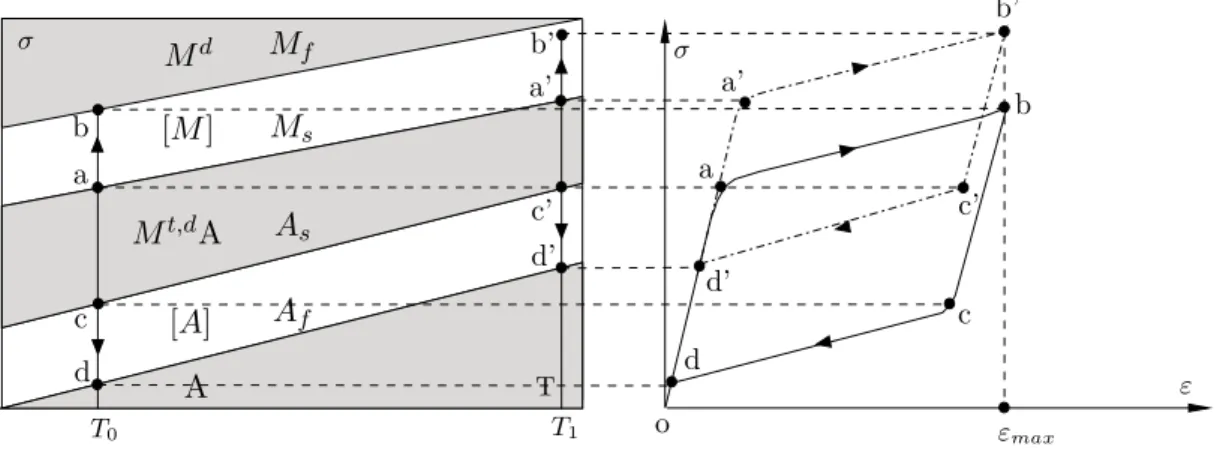
In the superelastic domain, the stress-temperature phase diagram shown in
Fig-ure 2.2 can be simplified by considering a temperatFig-ure range between Af and Md.
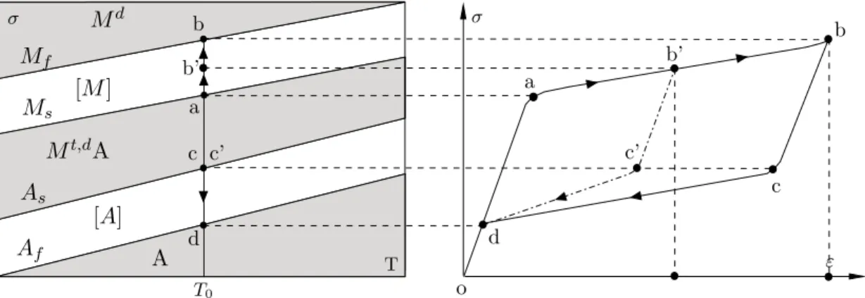
In Figure 2.5, a pseudo-static, isothermal superelastic cycle, together with the asso-ciated transformation path in the corresponding stress-temperature phase diagram is represented. Considering that the cycle is performed with a constant
tempera-ture, the forward transformation path, between points (a) and (b), and the inverse
2.2. GENERAL ASPECTS OF SHAPE-MEMORY ALLOYS 13
Martensite (detwinned)
exothermic transformation
endothermic transformation Austenite
(parent phase)
T > Af Deformation
Figure 2.4: Mechanism of superelasticity (after Otsuka and Wayman [124]).
associated with T = T0.
o
b
c
d a a
b
ε σ
T
σ
T0
A
c
d
[A] [M]
Mt,dA
Ms
Mf
As
Af
Md CM CM
CA
CA
Figure 2.5: Isothermal path on phase diagram and correspondent hysteresis.
To characterize the stress effect on the martensitic transformation, the Clausius-Clapeyron relation is often used [124]. The Clausius-Clausius-Clapeyron equation relates tem-perature and stress along the transformation strips of the SMA stress-temtem-perature phase diagram. This relation, for uniaxial stress, may be written as follows,
dσ
dT =−
∆H
εT0
(2.1)
whereσ is the uniaxial stress,ε is the transformation strain and ∆H is the enthalpy
of the transformation per unit volume for temperature T0 [29].
During the forward transformation, which is exothermic, an overall decrease in
the other hand, during the reverse transformation, which is endothermic, heat is
absorbed by the system and ∆H is positive.
The relation between temperature and the critical stress to induce the martensitic
transformation can be described by the material properties CM and CA. These
values represent the slope (dσ/dT) of the lines defining the boundaries of the SMA
transformation strips, represented in Figure 2.5. Although experimental results for the determination of critical stress values associated with the beginning and the end of the forward and inverse transformations do rarely yield precisely linear results, it is usual to admit that the relation between critical stress and temperature tends
to be approximately linear. It is generally assumed that both CM and CA have the
same value, constant over all temperature ranges [29]. This value is also referred to
as the Clausius-Clapeyron coefficient (CCC or αCC) [78].
2.2.3
Shape-Memory effect
The other manifestation of the thermoelastic martensitic transformation in SMAs is the so called shape-memory effect. Whereas stressed induced martensite consists of a single preferential variant according to the applied stress, martensite produced by cooling consists of a random mixture of several variants (including twins). Twin boundaries can be relatively easily moved by the application of stress. Movement of twin boundaries by stressing, called detwinning, results in change of orientation from one variant to another which is more favorably oriented to the direction of the applied stress. During the detwinning process of the martensitic crystal struc-ture, when facing an unidirectional loading, the stress remains almost constant until the martensite is completely detwinned. Crystals favorably aligned to the load
di-rection deform first, at a lower stress level, (o-a-b) in Figure 2.6. Less favorably
aligned crystals deform later, at higher stresses (b-c). Further straining causes the
elastic loading of the detwinned martensite (c-d). Unloading from any point in (
o-d) initially results in elastic unloading of the detwinned material. The deformation
recovered is much smaller than the one supplied by detwinning, giving the apparent impression of permanent deformation. This deformation can be recovered by raising
the temperature above Af, transforming the detwinned martensite back to
austen-ite; see Figure 2.7. This shape is maintained during cooling below Mf, when the
2.2. GENERAL ASPECTS OF SHAPE-MEMORY ALLOYS 15
first cause the slipping of the martensite lattices and eventually lead the specimen to
failure, corresponding to point (e’). The force exerted by a specimen when it
trans-Residual strain (recoverable trough heating)
Elastic deformation martensiteof twinned
Plastic deformation (Slipped martensite)
Elastic deformation martensite of detwinned Elastic deformation
of detwinned martensite
o c’
a
Unloading
e’
Failure
Stress
Strain c
d
e
f
Detwinning of martensite
b
Figure 2.6: Generic stress-strain response of a SMA below Mf (adapted from Shaw
and Kyriakides [?]).
T < Mf T < Mf T > Af T < Mf
T > Af Martensite
(twinned)
Deformation
(detwinning) Martensite
Deformation Heating
Austenite (parent phase)
Martensite (twinned)
Cooling
Heating
Figure 2.7: Mechanism of shape-memory effect (after Otsuka and Wayman [124]).
Finally, a sequence of martensitic transformations is shown in Figure 2.8, combining both a superelastic cycle and a shape-memory recovery.
Forward transformation
Inverse transformation
unloading with residual strain unloading with
no residual strain
Strain
T =As
T =Af
T< Mf
SUPERELASTIC
SHAPE MEMORY T> Af
Temperature
Strain Stress
Stress
Detwinning
Figure 2.8: Shape-memory and superelastic sequence. Three dimensional stress, strain and temperature diagram.
2.2.4
Internal friction
The martensitic transformation involves latent heat, i.e. energy is absorbed into the material or released to the surrounding environment, depending on the direction of the transformation. The energy generated during one tensile cycle is proportional to the volume fraction of formed martensite, reaching its maximum at the middle of the solicitation.
The other source of energy generation during martensitic transformation is the in-ternal friction. The amount of energy dissipated due to inin-ternal friction is always small compared to the latent heat of transformation [122]. It is generally accepted that internal friction, or damping capacity of SMAs, derives from the movement
2.2. GENERAL ASPECTS OF SHAPE-MEMORY ALLOYS 17
This energy loss due to interfacial motion enables a high degree of strain reversibil-ity while providing material damping, in contrast to dislocation based plasticreversibil-ity, in
which damping is associated with irreversible inelastic deformations [?]. Internal
friction is usually related to the dissipative response of a material when subjected to a cyclic deformation [90].
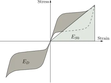
The energy dissipated in a cycle of harmonic vibrations corresponds to the area
enclosed by the hysteresis loop and is usually referred asED. It is usually defined for
a full cyclic deformation, comprising tension and compression. If such a deformation is applied on a SMA, the stress-strain curve in compression can be considered similar
to the one in tension [135]. ES0, in Figure 2.9, is the maximum strain energy [38].
Strain Stress
ES0
ED
Figure 2.9: Definition of energy dissipated ED in a superelastic loading cycle and
maximum strain energy ES0.
For one complete cycle, the total dissipated energy is then equal to twice the energy dissipated in tension. In Nitinol, depending on temperature and strain-rate, the maximum energy dissipated in tension can reach values as high as 40 to
50 J/cm3 [55].
To mathematically describe damping, the viscous damping element is most
com-monly used. The damping force fD is related to the velocity ˙u of the linear viscous
damper by fD =cu˙, where the constant cis called the viscous damping coefficient.
one of these mechanisms. Therefore, the damping coefficient of a given structure is chosen in such a way that the vibrational energy it dissipates equals the energy dissipated in all of the combined damping mechanisms present in the structure. This idealization is called equivalent viscous damping [38].
The most common method for defining the equivalent viscous damping is to equate the energy dissipated in a vibration cycle of the actual structure and an equivalent viscous system. The equivalent viscous damping as a measure of damping or internal friction in a structure is very advantageous since it is clearly defined in terms of observable quantities. For a given dynamic system, the stress-strain relation can be easily obtained through a cyclic loading experiment. The subsequent evaluation of
the area enclosed by the hysteresis, corresponding to the dissipated energy (ED), is
very simple to compute.
The energy dissipated by a viscous system is given by
ED = Z
fDdu (2.2)
where fD is the damping force. The steady-state vibrations of a
single-degree-of-freedom (SDOF) system due to an harmonic force can be described as u(t) =
u0sin(ωt−φ). The dissipated energy in one cycle of harmonic vibration equals
ED =
Z 2π/ω
0
(cu˙) ˙u dt = πcωu02 (2.3)
As the damping ratio, ζ is defined by
ζ = c
2mωn
(2.4)
and the natural undamped frequency of the system is defined by ωn =
p
k/m, expression (2.3) may be rewritten as
ED = 2πζ
ω ωn
ku02 (2.5)
2.3. VIBRATION CONTROL DEVICES 19
can be rewritten as
ED = 4πζ
ω ωn
ES0 (2.6)
or
ζ = 1
4π
ωn
ω ED
ES0
(2.7)
If the stress-strain hysteresis, and the correspondent ED, is determined at ω =ωn,
equation (2.7) specializes to
ζeq=
1
4π
ED
ES0
(2.8)
The damping ratio ζeq determined with ω = ωn would not be correct at any other
exciting frequency, but it would be a satisfactory approximation [38].
2.3
Vibration control devices
Technological applications built up of shape-memory components are designed to take advantage of the shape-memory effect and/or superelasticity. Regarding the shape-memory effect, three different categories are usually considered for the afore-mentioned applications, i.e., free recovery, constrained recovery and actuators [55]. Free recovery is when a shape-memory component is allowed to freely recover its original shape during heating, generating a recovery strain. If this recovery is pre-vented, constraining the material in its martensitic form while recovering, large stresses are developed, although no strain is recovered. These applications, based on a constrained recovery, include fasteners and pipe couplings and are the oldest and most widespread type of practical use [55]. In applications where there is both a recovered strain and stress during heating, such as in the case of a Nitinol spring being warmed to lift a ball, work is being done. Such applications are often further categorized according to their actuation mode, i.e. electrical or thermal.
control system. In a semi-active control system, mechanical energy is not added into the structural system nor to the control actuators. These devices are mostly passive control devices with controllable properties, and therefore have external energy requirements which are orders of magnitude smaller than ordinary active control systems [73].
Passive energy dissipation in a vibrating structure mainly occurs due to internal stressing, rubbing, cracking, and plastic deformations [73]. When facing a dynamic event, the amplitude of the structural vibrations varies inversely with the capacity of the structure to dissipate energy. As some structures show very low damping, they may experience large amplitudes of vibration even for moderately strong earth-quakes. Increasing the energy dissipation capacity of a structure is a very effective method to reduce the amplitudes of vibration. A great variety of different devices providing supplemental damping exist and have been already installed in structures all over the world, enhancing their energy dissipation capacity by converting kinetic energy into heat. These devices operate on principles such as frictional sliding, defor-mation of viscoelastic solids or fluids, yielding of metals and phase transfordefor-mations in metals or alloys. The latter method includes SE, which allows the material to dissipate a considerable amount of energy through hysteresis, while recovering from large nonlinear strains [73].
2.4
Seismic mitigation devices based on SMAs
Recent earthquakes in urban areas such as the Loma Prieta (1989) and the Northridge (1994) earthquakes, in the U.S.A., the Kobe (1995) earthquake, in Japan, the Ko-caeli (1999) earthquake, in Turkey, and the Nisqually (2001) earthquake, in the U.S.A, resulted in significant damage to the civil engineering infrastructure [104].
2.4. SEISMIC MITIGATION DEVICES BASED ON SMAS 21
drift can be associated with increased damage levels [68].
Meanwhile, several devices aimed to limit the inelastic behavior of critical structural members are being developed, in order to comply with these performance guidelines. These devices are based on three primary concepts: energy dissipation (damping), decoupling of the structure from the foundation (base isolation) and limiting the force transmission to critical load bearing members [168].
The current development of both passive and active vibration control devices based
on these concepts has led to a recent interest in the use of smart materials. A
relatively consensual definition of a smart material is proposed in [106]: a
struc-tural material that inherently contains actuating, sensing and controlling capabili-ties built into its microstructure. These materials undergo changes in one or more of their properties (chemical, mechanical, electrical, magnetic or thermal) in a direct response to an external stimuli associated with the environment surrounding the material. These changes are direct and reversible, with no need for an external
con-trol system [1]. SMAs are one class of smart materials that have shown significant
potential for exploitation as a cost-effective mean to control the response of civil engineering structures in both new and retrofit applications [49, 104].
2.4.1
Bracing systems
Most of the structural damages occurring in building structures during an earth-quake event, result from large inter-story drifts. The addition of passive energy dissipation bracing systems, connecting two consecutive storeys of the building, have been proved effective in limiting such inter-story drifts, preventing significant inelastic deformations in structural members [53].
Currently used bracing systems dissipate energy through yielding of metals, sliding friction between suitable surfaces, motion of a piston or plate within viscous fluid, ex-trusion of fluid through orifices or, finally, viscoelastic action of polymers. Recently, SMAs are being increasingly considered for bracing systems in structures, in order to limit inter-story and residual drifts, by providing additional energy dissipation capacities and re-centering capabilities [53].
on shake-table tests in small-scale steel framed prototypes, used to study Nitinol and copper-based cross-bracing systems; see Figure 2.10. These systems showed a significant decrease in the maximum inter-story drift values, with the use of SMA braces. Almost no residual displacements were experienced by the structural proto-types, due to the re-centering capability of the SMA material. Furthermore, in the
study conducted by McCormick et al. [103] an additional conventional steel braced
structure was analyzed, as a benchmark, that underwent yielding and buckling. This resulted in permanent story drifts and less effective seismic vibration control.
Figure 2.10: Small-scale steel framed prototype with SMA braces (adapted from
Boroscheck et al. [27]).
2.4. SEISMIC MITIGATION DEVICES BASED ON SMAS 23
by Dolce et al. [53] in a reinforced concrete structure. The aim of the experimental
program was to compare the behavior of structures endowed with innovative SMA-based devices to the behavior of conventional structures and of structures endowed with currently used passive control systems.
Figure 2.11: SMA-based energy dissipating and re-centering brace (adapted from
Dolce et al. [53]).
The addition of passive control braces in the reinforced concrete frame proved to convey great benefits to the overall seismic behavior of the structure. The seismic intensity producing structural collapse was considerably raised and the inter-story drifts and shear forces in columns were drastically reduced. The experimental out-comes have also shown that the new SMA braces can provide performances at least comparable to those provided by currently used devices.
Figure 2.12: Adaptive vibration control device for bracing systems (adapted from Zhang and Zu [177]).
2.4.2
Base isolation system
Although dampers are probably the most popular application for SMAs in struc-tures, their use has also been addressed in applications for base isolation systems. These systems are meant to decouple the superstructure from its foundation while also providing additional energy dissipation and re-centering capabilities. They fil-ter the seismic energy transferred from the ground motion to the superstructure so that the damage of the superstructure is attenuated [150]. Corbi [42] has imple-mented such an isolation device in a multi-degree-of-freedom (MDOF) elastic-plastic structural model of a building and demonstrated its efficacy in suppressing plastic deformations in the super-structure. A hybrid base isolation system, composed of linear elastomeric bearings, friction-pendulum bearings, SE austenitic wires and
magnetorheological (MR) dampers was proposed by Shook et al. [149], for
mitiga-tion of seismic momitiga-tions. To manage the superstructure response to ground momitiga-tions, each sub-component of the isolation system was designed for a specific task. The SE austenitic wires were used to supply recoverable hysteretic behavior and to serve as an additional restoring force. The isolation system comprehends a set of low-friction wheels in order to reduce the total length of the SMA installation while guaranteeing the effective length of the SMA wires.
Results showed that the proposed SE base isolation system could significantly reduce
base drifts, maintaining a favorable response from the superstructure. Dolce et
al. [54] also proposed a hybrid isolation system, based on both SMA and steel
components.
2.4. SEISMIC MITIGATION DEVICES BASED ON SMAS 25
Figure 2.13: Configuration of elastomeric bearings, friction-pendulum bearings, SE austenitic wires and magnetorheological dampers. Low-friction wheels for SMA wire
installation (adapted from Shook et al.[149]).
from the hazard of earthquakes. Wilde et al. [174] proposed an isolation system
combining a laminated rubber bearing with a SMA device. The isolation system uses the different responses of the SMA, at different levels of strain, to control the displacements of the rubber bearing for different excitation levels. It provides a stiff connection between the pier and the deck for small external loading. For a medium size earthquake, the SMA bars increase the damping capacity of the isola-tion system due to stress-induced martensitic transformaisola-tion of the alloy. Finally, for the largest considered earthquake, the SMA bars provides both hysteretic damp-ing and displacement control due to the hardendamp-ing of the alloys after completeness of the phase transformation. The SMA based isolation system also has an inherent re-centering ability due to the SE response of the alloy.
2.4.3
Bridge hinge restrainers
significant disruptions to the transportation network, posing a threat to emergency response and recovery as well as resulting in severe direct and indirect economic losses for a region. The unseating mechanism of a bridge during an earthquake, associated with an in-span hinge, is presented in Figure 2.14. The unseating at in-span hinge, during the 1994 Northridge earthquake, for an existing bridge and a bridge retrofit with traditional steel restrainer cables, taken from the NISEE (Na-tional Information Service for Earthquake Engineering) collection [82] is illustrated in Figure 2.15.
¨
y(t)
In-span hinge
Figure 2.14: Unseating of bridge at in-span hinge during an earthquake.
Several authors have studied the retrofit and rehabilitation of bridges, in order to
overcome their seismic vulnerabilities [8, 46, 48]. Andraweset al. [8] and DesRoches
2.4. SEISMIC MITIGATION DEVICES BASED ON SMAS 27
Figure 2.15: Unseating of bridge at in-span hinge during the 1994 Northridge earth-quake for an existing bridge and a bridge retrofit with traditional steel restrainer
cables (adapted from Johnson et al. [82]).
SMA restrainers
Figure 2.16: Restraining solution with SMA elements in a multi-span simply sup-ported bridge.
displacements at the abutment much more effectively than conventional steel cable restrainers. The large elastic strain range exhibited by SMA restrainers allows them to undergo large deformations while remaining elastic. In addition, the SE properties of the SMA restrainers result in energy dissipation at the hinges. Finally, evaluation of the multi-span simply supported bridge subjected to near-field ground motion showed that the SMA restrainer bars are extremely effective for limiting the response of bridge decks to near field ground motion. The increased stiffness of the SMA restrainers at large strains provides additional restraint to limit the relative openings in a bridge.
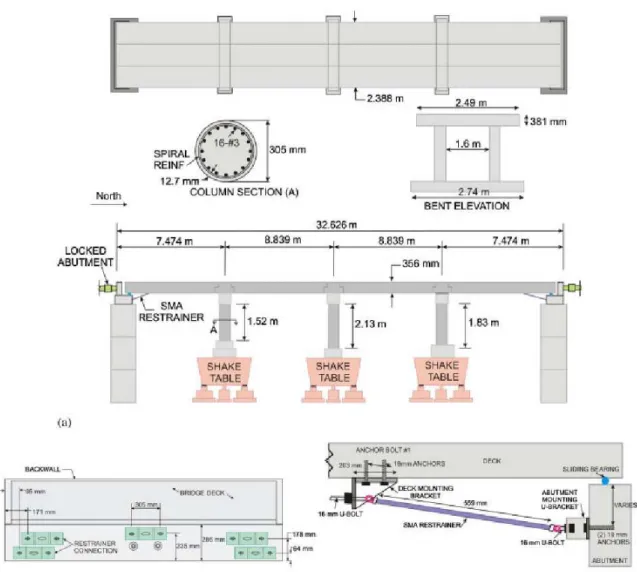
A large scale testing program was conducted by Johnson et al. [82], to determine
restrainer test setup, respectively, which comprise a representative multiple-frame concrete box girder bridge and the SMA restrainer cable.
Figure 2.17: Schematic of the test setup and SMA restrainer cable (adapted from
Johnson et al.[82]).
Figure 2.18: SMA restrainer test setup (adapted from Johnsonet al. [82]).