Dissertation
Master of Computer Engineering
Indoor Positioning System with Smart
Wi-Fi Antennas
Student: Marko Gašparović Supervisor: João Da Silva Pereira
Acknowledgements
I would like to express my gratitude to my supervisor João da Silva Pereira for his continuous support, guidance, knowledge and patience with me while working on this project. Without his help, the completion of this project would not be possible.
Special thanks go to Instituto Politécnico de Leiria and Escola Superior de Tecnologia e Gestão for providing me all the needed resources to work on and finish my dissertation. Also, a big thanks go to Instituto de Telecomunicações where I made high number of research which greatly helped me for my dissertation work.
And without a doubt my biggest support while working on this dissertation, my sister Ana and parents Ante and Jelena Gašparović, who supported all my actions. Thank you!
Abstract
The advancements of the indoor positioning system (IPS) in the recent years have been immense, yet we do not see the standardization of any solution. The system which is being used in many public scenarios is the Wi-Fi technology and the solution which we propose in this dissertation would not require change of infrastructure, but rather reusing existing one and simply enhancing it. This solution is low-cost and with relatively high precision considering current precision of Global Positioning System (GPS) of five meters. In this dissertation prototype is designed with motorized directional antennas using signal strength of two ESP8266. These position measurements are calculated and presented via micro controller and a Wi-Fi enabled device – ESP8266. Together with Yagi antenna, this solution has shown extremely good IPS characteristics and possibility to be implemented in real-case scenarios.
Index of Figures
Figure 1 - HTC Vive wisth its components [5] ... 4
Figure 2 - MIT Chronos determining the distance [6] ... 5
Figure 3 - Broadcom BCM47755 chip [9] ... 6
Figure 4 - GPS signal different frequencies [11] ... 7
Figure 5 - Positioning RSSI-AOA [17] ... 9
Figure 6 - GPS coverage [20] ... 13
Figure 7 - ESP-12E Board with ESP8266 chip - pinout [24] ... 16
Figure 8 - ESP-12E NodeMCU ... 17
Figure 9 - Yagi antenna parts [26] ... 18
Figure 10 - Yagi Antenna ... 18
Figure 11 - 3d printed Yagi antenna [29] ... 19
Figure 12 - Servo motor [31] ... 20
Figure 13 - Wi-Fi analyzer - mobile application to detect Wi-Fi signal strength ... 21
Figure 14 - Wi-Fi analyzer - graphical time view in seconds of the ESP8266 signal ... 22
Figure 15 - Trilateration [32] ... 23
Figure 16 - FDMA, TDMA and CDMA graph comparison [34] ... 25
Figure 17 - ESP8266 with servo motor mechanism ... 28
Figure 18 - Real-world simulation testing scenario... 29
Figure 19 - Antenna angles test ... 30
Figure 20 - Signal strength (1) ... 31
Figure 21 - Signal strength (2) ... 31
Figure 22 - Signal strength (3) [38] ... 32
Figure 23 - Graphical representation of the Figure 21 [38] ... 33
Figure 24 - Graphical representation of a 360 degrees test [38] ... 34
Figure 25 - Effect of a standing wave [39] ... 34
Figure 26 - Measurement 1 - without Yagi antenna ... 36
Figure 27 - Measurement 2 - with Yagi antenna ... 37
Figure 28 - Measurement 3 - combining antennas ... 38
Figure 29 - Measurement 4 - double Yagi antennas ... 39
Figure 30 - Android mobile hotspot ... 40
Figure 31 - Signal output value ... 43
Figure 32 - ESP8266 serial output and the scan movement of the antenna ... 43
Figure 33 - Room layout ... 44
Index of Tables
Table 1 - Average indoor location estimation error between two transmitters - Golay, Chu,
ZigBee and OPDG [15] ... 8
Table 2 - Frequency comparison ... 14
Table 3 - 802.11 protocol comparison [22] ... 15
Table 4 - Servo motor specifications [31] ... 20
List of Acronyms
2D 2-dimensional
3D 3-dimensional
AOA Angle-of-arrival
AP Access Point
ARM Advanced RISC Machine
CDMA Code-Division Multiple Access CPU Central Processing Unit
FM Frequency Modulation
GPS Global Positioning System
IT Information Technology
LFSR Linear-Feedback Shift Register LIDAR Light Detection and Ranging
LOS Line-of-sight
LSR Linear Recursive Sequences
OPDG Orthogonal Perfect DFT Golay
RF Radio Frequency
RSS Received Signal Strength TDOA Time-difference-of-arrival
TOA Time-of-arrival
Index
Contents
Acknowledgements ... iii
Abstract ... v
Index of Figures ... vii
Index of Tables ... ix
List of Acronyms ... xi
Index ... xiii
1. Introduction ... 1
2. State of the Art ... 3
2.1. HTC Vive – Virtual Reality (VR) ... 3
2.2. MIT - Chronos ... 4
2.3. Broadcom chip - BCM47755 ... 6
2.4. Other findings ... 7
2.4.1. Tesla ... 7
2.4.2. Light Detection and Ranging (LIDAR) and GPS signal ... 7
2.4.3. Exploring Vision-Based Techniques ... 8
2.5. Josip Bagaric - Indoor Positioning System for Mobile Devices ... 8
2.6. Daniela Taipe - Sistema de Localización Indoor y Outdoor... 9
2.6.1. Mathematical method – Triangulation ... 10
2.7. Positioning System (PS) ... 12
2.8. Global Positioning System ... 12
2.9. Indoor Positioning System ... 14
2.10. Wireless technologies ... 14
2.11. Wi-Fi ... 14
2.12. Frequency modulation (FM) signal ... 15
3. Devices and Methodology ... 16
3.1. ESP8266 ... 16
3.2. Yagi antenna ... 17
3.3. Servo motor ... 19
3.5. Triangulation ... 22 3.5.1. Lateration ... 22 3.5.2. Angulation ... 23 3.6. Sequences ... 23 3.6.1. CDMA ... 23 3.6.2. M-sequences ... 24 4. Results ... 26
4.1. Real-time graphical measurements ... 26
4.2. Standing wave... 33
4.3. Two-dimensional test scenarios ... 34
4.4. Simulation of a real-case scenario ... 38
4.4.1. Network scan ... 39
4.4.2. Logic ... 39
4.4.3. Signal output value ... 41
4.4.4. Output – Phone’s localization ... 43
5. Conclusions ... 46
6. Future work ... 48
6.1. Mobile application ... 48
6.2. Performing tests in the real-world scenarios ... 48
7. Bibliography ... 50
8. Annex ... 54
[P1] - J. Pereira, M. Gasparovic, M. P. M. Ferreira, INDOOR POSITIONING SYSTEM AND METHOD, 109950, March 2017, Portuguese Pending Patent. ... 54
[P2] - J. Pereira, M. Gasparovic, P. Pujari, G. Manjunath, Standing Wave Cancellation and Shadow Zone Reducing Wireless Transmitter, System and Respective Method and Uses, 109332, April 2016, Portuguese Pending Patent. ... 70
[P3] - J. Pereira, M. Gasparovic, M. P. M. Ferreira, A TUNABLE FIBER BRAGG GRATING DEVICE, A SUPERSTRUCTURED TUNABLE FIBER BRAGG GRATING DEVICE AND RESPECTIVE USES AND OPERATING METHODS, 109554, July 2016, Portuguese Pending Patent. ... 93
[P4] - J. Pereira, M.P.M. Ferreira, M. Gasparovic, Tunable Super-Structured Fiber Bragg Gratings with Perfect Sequences Based on m-Sequence, Journal of Electronic Science and Technology, JEST, Vol. 15, No. 4, pp. 358 - 363, December 2017. ... 103
[P5] - J. Pereira, M.P.M. Ferreira, M. Gasparovic, Tunable super-structured fiber Bragg gratings with perfect sequences, OAHOST - Open Access Journal, Vol. 1, No. 1, pp. 1 - 15, October 2016. ... 110
[P6] - J. Pereira, M.P.M. Ferreira, M. Gasparovic, Tunable Super-Structured Fibre Bragg Gratings with Perfect Sequences, Energy Material Nanotechnology, Beijing, China, Vol. 1, pp. 29 - 29, April 2016. ... 126 [P7] - M. Gasparovic, P. Nicolau, A. Marques, C. Silva, L. Marcelino, On Privacy in User Tracking Mobile Applications, Information Systems and Technologies (CISTI), 2016 11th Iberian Conference, 16191805, 5-18 June 2016. ... 133
1. Introduction
By seeing the world around, it is obvious that technology has permeated our lives. Every daily action we do, most of the time has some type of interaction with the technology. It is hard to imagine even one day without our phone or a computer and just thirty years ago all that was minimal or nonexistent. Computing has involved drastically in the recent years and the technical changes are happening exponentially faster. There was a lot of development and contribution of researchers around the world to help us to get to the point where we are now.
This dissertation is based on a research about indoor positioning system [1]. The methodology and approach of implementing the IPS is explained in detail. All the devices and technologies will be elaborated together with testing scenarios and results.
The goal of this dissertation is an implementation of a low cost indoor positioning system using two major components: Wi-Fi (Wireless Fidelity) micro controllers ESP8266 and smart motorized directional antennas. Global positioning system (GPS) is widely used in the unobstructed line of sight (LOS). As it is well known, GPS does not work inside the buildings. In addition, a problem of a GPS is that accuracy is far too big to consider it, when implementing it into indoor scenarios. In this dissertation, the new indoor localization system is made using a network of ESP8266, Wi-Fi emitter devices that work inside the buildings. A prototype is designed with directional antennas using signal strength of two micro controllers ESP8266. These signal strengths are measured and the position is calculated using the triangulation method. Finally, this gives us an opportunity for further development of an application where the user would be able to navigate through certain indoor scenario such as big shopping centers, airports etc.
This work was based on my research published in the following publications:
[P1] - J. Pereira, M. Gasparovic, M. P. M. Ferreira, INDOOR POSITIONING SYSTEM AND METHOD, 109950, March 2017, Portuguese Pending Patent.
[P2] - J. Pereira, M. Gasparovic, P. Pujari, G. Manjunath, Standing Wave Cancellation and Shadow Zone Reducing Wireless Transmitter, System and Respective Method and Uses, 109332, April 2016, Portuguese Pending Patent
[P3] - J. Pereira, M. Gasparovic, M. P. M. Ferreira, A TUNABLE FIBER BRAGG GRATING DEVICE, A SUPERSTRUCTURED TUNABLE FIBER BRAGG GRATING DEVICE AND RESPECTIVE USES AND OPERATING METHODS, 109554, July 2016, Portuguese Pending Patent.
[P4] - J. Pereira, M.P.M. Ferreira, M. Gasparovic, Tunable Super-Structured Fiber Bragg Gratings with Perfect Sequences Based on m-Sequence, Journal of Electronic Science and Technology, JEST, Vol. 15, No. 4, pp. 358 - 363, December 2017.
[P5] - J. Pereira, M.P.M. Ferreira, M. Gasparovic, Tunable super-structured fiber Bragg gratings with perfect sequences, OAHOST - Open Access Journal, Vol. 1, No. 1, pp. 1 - 15, October 2016.
[P6] - J. Pereira, M.P.M. Ferreira, M. Gasparovic, Tunable Super-Structured Fibre Bragg Gratings with Perfect Sequences, Energy Material Nanotechnology, Beijing, China, Vol. 1, pp. 29 - 29, April 2016.
[P7] - M. Gasparovic, P. Nicolau, A. Marques, C. Silva, L. Marcelino, On Privacy in User Tracking Mobile Applications, Information Systems and Technologies (CISTI), 2016 11th Iberian Conference, 16191805, 5-18 June 2016
2. State of the Art
Indoor positioning system has a significant impact in different aspects of life. With Indoor Positioning System (IPS) and positioning system in general, more solutions are being discovered with the importance of orientation in space. Nowadays, if we travel around the globe, rarely we can see people using standard maps to find directions. With the technology swiftly growing this has been revolutionized in a way that only a smartphone and an application is needed to abandon traditional maps. The development of the indoor positioning system doesn’t mean it must necessarily be related only to the research and tests being discovered in this area. There are many research, patents and products which can help us in receiving more ideas and giving us an opportunity to have an approach from a different angle. In the following sections, we will describe some of the essential elements which can have a beneficial spot in indoor positioning system.
It is possible to calculate indoor positioning in a multitude of ways and we can choose from variety of wireless technologies. One of the methods which is gaining popularity and many of the systems try to use it is a Wi-Fi access point based to create a Wi-Fi Positioning System (WPS). In this dissertation we are also working with the mentioned technology, however, in the following paragraphs we will not only concentrate on Wi-Fi based research, but rather on different technologies to discover more ways on how to create a reliable indoor positioning system.
2.1. HTC Vive – Virtual Reality (VR)
Virtual technology is developing rapidly and research proves that VR technology is the development of all aspects of life and that will have a big impact on the life in the future [2]. We are all experiencing this impact while the technology is developing and it is important to research and observe the VR solutions discovered for positioning and orientation. HTC Vive is one of the examples where its technology requires high precision without errors and latency. Every VR typically consists of a head mounted display and a position and orientation tracking system. To understand better the setup of the VRs refer to the following paper [3] where they explain parts of another product from the VR technology – Oculus rift. In addition to general components, Vive has two controllers and two infrared laser emitter units which are designed to track an observer who freely moves through space of up to 4 x 4 meters [4].
Figure 1 - HTC Vive with its components [5]
Relatively expensive head-mounted display (HMD) and position and orientation tracking system could enable a far larger number of researches to conduct experiments with moving observers in VR environments. The first commercially available system that has the promise to fulfil this ambition is the HTC Vive. In the tests performed [4] we see position and orientation tracking capabilities. Tracking is subjectively fast and supports good presence, the system end-to-end latency is low at 22 ms, and the noise level in the tracker output is low. This example serves as an important point for its insights in the interaction between one point which is acting as an information receiver and the other which is information transmitter. We were unable to find a specific value for a HTC Vive precision, however, knowing its capabilities in tracking in-game experience, precision is measured in millimeters.
2.2. MIT - Chronos
Researchers from Massachusetts Institute of Technology (MIT) have developed technology which can locate the Wi-Fi enabled devices within centimeters [6]. Their invention/technology is called Chronos [7] and relies on making the devices emulate multi-gigahertz wideband radios.
Chronos works in a way where two Wi-Fi devices, a transmitter and a receiver, change all 35 frequency bands every 2 to 3 microseconds calculating the distance and the angle between the devices. At each band receiver is comparing the phase difference so it can calculate the time of flight, therefore, determine the distance between the devices. In other words, Chronos stitches the measurements from different Wi-Fi bands to calculate signal’s travel distance, by multiplying the time of the flight by the speed of the light [8]. Please refer to the Figure 2 to understand better the ration between frequency and the distance and how the travel distance is calculated. Knowing both the distance and the angle allows to compute the user’s position using just one access point.
Figure 2 - MIT Chronos determining the distance [6]
The accuracy of this invention is about 10 times the accuracy of the GPS since in testing the MIT researchers could locate the device within 65 cm using the devices from everyday environment using only an application. However, there are few limitations of this invention. Each device must perform a one-time distance calibration and at that time, both devices need to be in a still position. If the devices are moving relative to each other, accuracy drops significantly. Additionally, there are issues with the delay of the transmitting packet signal and it can bounce of different objects for not satisfying accuracy results.
2.3. Broadcom chip - BCM47755
Company Broadcom has announced testing of the first chip which can have an advantage as a new technology in global navigational system. Its accuracy should enable smartphones improved 30 cm accuracy, which is exceptionally better than today’s 5 meters. Moreover, Broadcom is stating that the chip will be able to work even in the streets which are surrounded by tall concrete buildings with usage of only half of the power which today’s era of chips are using.
Figure 3 - Broadcom BCM47755 chip [9]
Name of the chip is BCM47755 and it has been told that it will be incorporated in some of the smartphones in 2018, however, there is no info which smartphones model could include this chip [10]. The BCM47755 supports two frequencies (L1+L5) see Figure 4 highlighted area, and as a result, achieves lane-level accuracy outdoors and much higher resistance to multipath and reflected signals in urban scenarios, as well as higher interference and jamming immunity [9].
Figure 4 - GPS signal different frequencies [11]
Furthermore, the BCM47755 incorporates numerous technologies that enable ultralow power consumption in both the location function and the sensor hub function. The device features a low-power Radio Frequency (RF) path, a Big/Little Central Processing Unit (CPU) configuration composed of an Advanced RISC Machine (ARM)-based 32-bit Cortex-M4F (CM4), an ARM-based Cortex-M0 (CM0), and is built in a 28 nm process [9].
2.4. Other findings
In this section we describe some of the findings which are related to this work and can be of a potential value for the future of indoor positioning system development.
2.4.1. Tesla
According to the Vice article [12] where it says that Tesla’s system estimates the position of the car in the tunnel by the steering wheel rotation and speed of the wheels, with the Broadcom chip (2.3) where the GPS precision would be narrowed to 30 cm it could detect the person with the smartphone exact position when entered into enclosed space and it can track the user by counting the steps made using accelerometers and position of the phones using gyroscope.
2.4.2. Light Detection and Ranging (LIDAR) and GPS signal
In the paper [13] the aim is to introduce the GPS positioning results into indoor environment and to combine ultra-wide band (UWB) indoor positioning method with the coordinate information of point cloud data. Their method combines GPS signals and point cloud data effectively, taking advantage of the characteristics of point cloud such as high density, high precision and containing geographic information. According to the results of their experiments, the precision of indoor positioning achieves level which is sub-meter.
2.4.3. Exploring Vision-Based Techniques
This paper describes investigation of utilizing image-based techniques together with context information to provide an outdoor positioning system. They named the system Human-centric Positioning System, i.e., HoPS. The system revolves around humans rather than machines. As described, humans can conveniently trigger the system as necessary by leveraging wearables like Google Glass [14].
2.5. Josip Bagaric - Indoor Positioning System for Mobile Devices
Proposed solution for IPS for mobile devices in the thesis by Josip Bagaric was based on the communication of the FM transmitters and receivers [15]. This communication was tested using four different codes – Golay, Chu, OPDG and ZigBee, from which only Orthogonal Perfect DFT Golay (OPDG) and ZigBee showed satisfying results. The OPDG coding sequences have perfect autocorrelation properties therefore they are a good candidate to be used in asynchronous communication systems. The properties of the OPDG coding sequences allow for enhanced detection of codes. On the other hand, a key component of the ZigBee protocol is the ability to support mesh networking. In a mesh network, nodes are interconnected with other nodes so that multiple pathways connect each node. Connections between nodes are dynamically updated and optimized through sophisticated, built-in mesh routing table [16]. Table 1 - Average indoor location estimation error between two transmitters - Golay, Chu, ZigBee and OPDG [15]
Code Family Average estimation error
Golay 13.48 m
Chu 14.28 m
ZigBee 7.99 m
OPDG 3.67 m
Research done in this thesis shows us following results, displayed in Table 1 shows that using the OPDG codes was possible to estimate the position of the receivers between two transmitters with an error near 3.5 meters, when a frequency carrier around 100 MHz is used. Also, this shows better estimation properties than ZigBee, Golay and Chu codes, which had an error higher than 7, 13 and 14 meters respectively [15].
We wanted to continue the work and try to acquire better results, but this showed us that different approach might be needed to obtain better results. With use of Wi-Fi technology and directional antennas precision is narrowed down to centimeters.
2.6. Daniela Taipe - Sistema de Localización Indoor y Outdoor
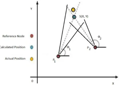
In order to use the Angle of Arrival (AoA) technique explained in the section 4.5, we will use the mathematical method described in the dissertation of Daniela Taipe [17]. Figure 5 shows the arrangement of antennas, which allows estimating the Received Signal Strength (RSS) in a certain angular interval through the AoA method. Each reference node (A, B) must have a known location with coordinates (Xi, Yi) (i = 1, 2, ...). These nodes are making scan movement
and locating the maximum intensity of the signal emitted by the target. This is measured by angles representing the direction of propagation α and β. [17]
Figure 5 - Positioning RSSI-AOA [17]
To understand the explanation, we used image from Daniela’s dissertation Figure 5, and below is the English version.
2.6.1. Mathematical method – Triangulation
After the angle measurements, it is necessary to find the line that symbolizes the direction of maximum propagation. This calculation is made to each of the reference points or nodes (𝑃𝑅) in this case A and B, with previous information of their coordinates (𝑋𝑖, 𝑌𝑖) and their respective angles (α and β), in addition to the point of intersection between them (𝑀′= (𝑋′, 𝑌′)), through
the equation of the line (1) (2) (3). Line AM’ 𝑚 = 𝑆𝑙𝑜𝑝𝑒 = tan 𝛼 = 𝑌 ′− 𝑌 1 𝑋′− 𝑋 1 ( 1 ) tan 𝛼 (𝑋′− 𝑋1) = 𝑌′− 𝑌 1 ( 2 ) Where 𝑋′tan 𝛼 − 𝑋1tan 𝛼 = 𝑌′− 𝑌1 ( 3 )
Then we obtain following equations which represent X' and Y':
𝑌′ = 𝑋′tan 𝛼 − 𝑋1tan 𝛼 + 𝑌1 ( 4 ) 𝑋′= 𝑌 ′− 𝑌 1+ 𝑋1tan 𝛼 tan 𝛼 ( 5 ) Line BM’ 𝑚 = 𝑆𝑙𝑜𝑝𝑒 = tan 𝛽 = 𝑌 ′− 𝑌 2 𝑋′− 𝑋 2 ( 6 ) tan 𝛽 (𝑋′− 𝑋2) = 𝑌′− 𝑌2 ( 7 ) Where 𝑋′tan 𝛽 − 𝑋2tan 𝛽 = 𝑌′− 𝑌2 ( 8 )
𝑌′= 𝑋′tan 𝛽 − 𝑋 2tan 𝛽 + 𝑌2 ( 9 ) 𝑋′= 𝑌 ′− 𝑌 2+ 𝑋2tan 𝛽 tan 𝛽 ( 10 )
With previously obtained equations, we calculate X' and Y'. Using X' using equations from (4) and (10), we acquire equation (11).
𝑋′= 𝑋1tan 𝛼 − 𝑋2tan 𝛽 + 𝑌2− 𝑌1
tan 𝛼 − tan 𝛽 ( 11 )
Similarly, equations (5) and (11) are used, which returns Y' in equation (12).
𝑌′ = (𝑋1− 𝑋2) tan 𝛼 tan 𝛽 − 𝑌1tan 𝛽 + 𝑌2tan 𝛼
tan 𝛼 − tan 𝛽 ( 12 )
Finally, equations (11) and (12) allow the localization of the node M' (X', Y'), as shown in Equation (13):
𝑀′= 𝑋1tan 𝛼 − 𝑋2tan 𝛽 + 𝑌2− 𝑌1
tan 𝛼 − tan 𝛽 ,
(𝑋1− 𝑋2) tan 𝛼 tan 𝛽 − 𝑌1tan 𝛽 + 𝑌2tan 𝛼
tan 𝛼 − tan 𝛽 ( 13 )
The advantage of using AoA position estimation is that it does not need to use many devices for both 3D and 2D measurement, in addition it doesn’t require a time synchronization.
2.7. Positioning System (PS)
A PS is a system for determining the location of an object in space. It is a way to identify the location of certain object using specific positioning system technologies. There are variety of technologies, which are used regarding several factors. Is the system made for outdoor or indoor scenarios and what level of precision does the system need? Technologies for this task exist ranging from worldwide coverage with kilometer accuracy to workspace coverage with centimeter accuracy. In the next paragraph, we will explain the Global Positioning System (GPS), since it is the most used outdoor geo-localization system, its strengths and weaknesses and most importantly how it is related to this work.
2.8. Global Positioning System
A global positioning system (GPS) is used for estimating the position of a mobile object such as a mobile phone in a global geometrical region which includes a GPS satellites and a GPS receiver for receiving radio waves from the satellites [18]. As it is well known GPS to function properly needs satellite and receiving GPS device to be in a line of sight (LOS). If this is not accomplished satellites are unable to locate device, thus, we are unable to estimate the position of the device. In the next paragraph, we will point out the advantages and disadvantages of GPS.
Advantages of GPS o Used worldwide
o Available in almost every point on earth (see Figure 7)
o Relatively small error rate for outdoors (avg. ≤7.8 m with 95% probability) [19]
Disadvantages of GPS
o Error rate too high for precise location estimation o Attenuated by solid objects
o Cannot work without LOS
The GPS sounds like a perfect solution for determining location, however there is one big weakness of this technology that prevents being used in closed spaces. The signals of the GPS are using wave frequency which until it reaches the ground it attenuates and scatters by roofs,
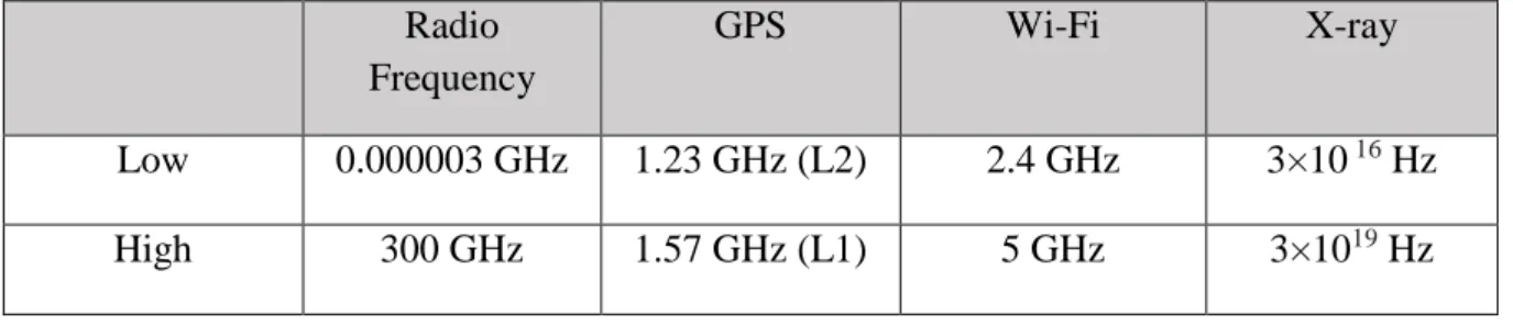
walls and other objects so it becomes unusable without LOS. A GPS device to work properly needs LOS with the satellites to precisely determine where the device is physically located. Besides problem of LOS due to walls and rooftops when using GPS inside of a building, there are also numerous other barriers which can interfere and make it impossible to locate device precisely or even to locate device at all. Signals which are using short wavelengths the energy is very high, like x-rays and gamma rays. These signals go through things solely because of their high energy. At lower energies (longer wavelengths) such as RF signals, the waves interact with the material in various ways so that they can get absorbed, refracted, reflected, and re-emitted. The frequencies of Wi-Fi and GPS does not differentiate by much (see Table 2), however here is also important the energy of the signal and how close is the emitter from the receiver.
On the Figure 7 we can see the position of the satellites around the globe. There are 24 GPS satellites from which 21 active and 3 passive ones (spare) which are in the orbit approx. 17.000km above the ground. They are positioned so that from any point on earth four satellites will be above the horizon. Every satellite consists of:
Computer Atomic clock Radio
Each satellite broadcasts the position change and time, and on the ground, every GPS receiver on smartphones, gadgets etc. calculates triangulation between 3 of the 4 satellites and the result is provided in the geo-position as latitude and longitude.
Table 2 - Frequency comparison Radio Frequency GPS Wi-Fi X-ray Low 0.000003 GHz 1.23 GHz (L2) 2.4 GHz 3×10 16 Hz High 300 GHz 1.57 GHz (L1) 5 GHz 3×10¹⁹ Hz
2.9. Indoor Positioning System
An indoor positioning system is a method of localizing a person/object in an indoor environment by identifying the orientation and direction of a person/object to provide a true location of the person/object without navigation errors [21].
2.10.
Wireless technologies
Here we describe one of the most common wireless technologies which are being used for IPS among others.
2.11.
Wi-Fi
In this section, we will cover about Wireless Fidelity (Wi-Fi) since this is the main technology used in this dissertation. We used Wi-Fi as a base to this project, where we use it as a main source of communication and positioning system.
Wi-Fi technology is mainly used for wireless local area networking which is based on the IEEE 802.11 standards. There are numerous devices which are using Wi-Fi technology including smartphones which nowadays every person has at least one and this is one of the reasons why this technology is suitable option for indoor positioning system. Devices which are Wi-Fi compatible can connect to the wireless access point (AP) and in our case, we used it as a transmitter of the Wi-Fi signal. When there are objects which could interfere with the signal such as walls, tables, etc. the range of AP is usually around 20 meters to 70 meters depending on the exact standard shown in Table 3. This value increases outdoors or in open spaces and signal can reach much further distance as shown in the table. These 20 to 70 meters indoor can be increased by using directional Yagi antenna which uses frequency carrier of 2.4 gigahertz.
Table 3 - 802.11 protocol comparison [22] 802.11 Protocol Freq (GHz) Bandwidth (MHz) Approximate indoor range Approximate outdoor range - 2.4 20 20 m 100 m a 3.7/ 5 20 35 m 120 m b 2.4 20 35 m 140 m g 2.4 20 38 m 140 m n 2.4/5 20 - 40 70 m 250 m
2.12.
Frequency modulation (FM) signal
FM broadcasting is a method of radio broadcasting using frequency modulation (FM) technology. To generate a frequency modulated signal, the frequency of the radio carrier is changed in line with the amplitude of the incoming audio signal [23]. Some of the advantages of using FM signals above others is their resilience to noise, easiness to apply modulation at a low power stage of the transmitter and a possibility to use efficient RF amplifiers with frequency modulated signals: There have been several attempts to create and IPS using this technology and one of them is presented here [15].
3. Devices and Methodology
In this chapter we are going to describe devices and application which were used in this project and explain how they work as well as the technologies related to this work.
3.1. ESP8266
ESP8266 is a low-cost Wi-Fi chip with full TCP/IP stack and MCU (Micro Controller Unit) capability. The ESP8266 is capable of either hosting an application or offloading all Wi-Fi networking functions from another application processor. On the image below, you can see the pins structure and this board can be directly connected to a computer via micro USB cable to power it up and to transfer the written programs in it. The IDE for this board is Arduino application.
Figure 8 - ESP-12E Board with ESP8266 chip - pinout [24]
The exact model used in this project is ESP8266 ESP-12E NodeMCU which we can see on the Figure 8 and Figure 9.
Figure 9 - ESP-12E NodeMCU
3.2. Yagi antenna
A Yagi–uda antenna, commonly known as a Yagi antenna, is a directional antenna consisting of a driven dipole, a parasitic dipole reflector and one or more parasitic dipole directors. All the elements usually lie on the same plane and can be distributed symmetrically [25]. The Yagi antenna consists of a single driven element, typically a dipole. This is the only part of the antenna where the signal is applied. The other parts are parasitic elements, meaning they either reflect or help transmitting the energy in particular directions [26]. Yagi antenna is an example of a multielement parasitic array [27]. A parasitic array consists of one or more parasitic elements with a driven element. The amount of power gain depends on the lengths of the parasitic elements and the spacing between them such as in Yagi antenna [28]. The Yagi antenna shown in Figure 10 has three directors. The greater number of parasitic elements used, the greater the gain. However, a greater number of such elements causes the array to have a narrower frequency response as well as a narrower beam width. Therefore, proper adjustment of the antenna is critical. The gain does not increase directly with the number of elements used. For example, a three-element Yagi array has a relative power gain of 5 dB. Adding another director results in a 2 dB increase. [27]
Figure 10 - Yagi antenna parts [26]
On the image below, we can see the type of Yagi antenna used for this project. As shown in the Figure 11 this Yagi antenna consists of six elements where element A is being a reflector, element B the radiator and C-F directors.
Figure 11 - Yagi Antenna
On the Figure 12 is shown custom made directional Yagi antenna for 3D printed which is used for WLAN signal. It is adjusted for 2.4 Ghz WLAN and optimizing the Wi-Fi environment
[29]. Uses 1 mm diameter copper rods. Position - Length: A - 59 mm B - 52 mm C - 51 mm D - 50.5 mm E - 50 mm F - 49 mm
Figure 12 - 3d printed Yagi antenna [29]
3.3. Servo motor
A servo motor is a rotary actuator that allows precise control of angular positions, velocity and acceleration. The pulse is fed to the servo via a control line. The control line does not supply power to the motor directly it is an input to a control chip inside the servo and as such it does not have to supply much current to the servo [30]. For our project, servo motor is receiving an input signal from control device to scan the room as well as an output device to send its current angle value. Also, we used servo as facilitating device to automate some of the measurements. On the Figure 13 is shown the type of the servo used in this project.
Figure 13 - Servo motor [31]
This servo motor has very good specifications and that is the reason why it was used in this project to motorize Yagi antennas. These specifications are shown in the table below.
Table 4 - Servo motor specifications [31]
Specifications
Modulation: Analog
Torque: 4.8V: 25.00 oz-in (1.80 kg-cm)
Speed: 4.8V: 0.12 sec/60° Weight: 0.32 oz (9.0 g)
Dimensions: Length: 0.91in (23.0 mm)
Width: 0.4in (12.2 mm)
Height: 1.14 in (29.0 mm)
Motor Type: 3-pole
Gear Type: Plastic
Rotation/Support: Bushing
Pulse Width: 1.1.
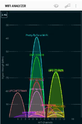
3.4. Wi-Fi analyzer app
The ’Wi-Fi analyzer app’ application detects all existing Wi-Fi networks in the environment, with their corresponding signal strength and channels. As shown in Figure 14 we see ESP139610 network – the network of our ESP8266 is detected with all other Wi-Fi signals in range. Also, there are a different view options which can help us in detecting the correct signal and performing measurements.
Figure 14 - Wi-Fi analyzer - mobile application to detect Wi-Fi signal strength
Below in the Figure 15 we can see the graphical representation of the Wi-Fi signal shown in real-time with its oscillations. This type of graphical interface helped us to get the precise graphs without margin for errors.
3.5. Triangulation
Triangulation is the technique using the geometric properties of triangles to compute objects’ location. The location is estimated relatively to some known framework. Triangulation has two derivations; Lateration and Angulation.
3.5.1. Lateration
Lateration is the technique to locate an object by measuring its distance from multiple reference positions, while angulation is the technique used to locate an object by computing angles or bearings relative to multiple reference positions. This technique must have at least three non-collinear nodes that form a 2-dimensional calculation, called trilateration. See Figure 16.
Figure 16 - Trilateration [32]
As shown in Figure 16 the black points represent the reference nodes (P1, P2, P3) with their respective radius the distance (r1, r2, r3). By relating them, the objective is estimated (B). This method is based on following techniques: Time of Arrival (ToA) / Time of Flight (ToF), Time Difference of Arrival (TDoA), Round-Trip Time of Flight (RToF), Received Signal Strength Indication (RSSI).
ToA/ToF - is the travel time of a radio signal from a single transmitter to a remote single receiver.
TDoA - is the technique in which the time of arrival of a specific signal, at physically separate receiving stations with precisely synchronized time references, are calculated. RToF - This technique measures the round- trip time by the signal from the transmitter
RSSI - is a measurement of the power present in a received signal.
3.5.2. Angulation
Angulation is a technique like lateration with the difference that it uses angles to estimate the position. It is known as the direction of arrival (Direction of Arrival, DoA) or angle of arrival (AoA). This localization method is used in this project in correlation with Wi-Fi. The system consists of Yagi antennas placed around the room to be able to be implemented together with this technique. These antennas are rotary and directional that sweep in a certain range, to receive the strongest signal from a mobile device.
3.6. Sequences
The autocorrelation function of a sequence is a measure for how much the given sequence differs from its translates. Periodic binary sequences with good correlation properties have important applications in various areas of engineering [33]. Golay, Chu, OPDG, ZigBee codes are sequences that have been used previously in an indoor position system.
3.6.1. CDMA
CDMA (Code-division multiple access) is an example of multiple access, where several transmitters can send information simultaneously over a single communication channel. This allows several users to share same bandwidth. There is no restriction on time and frequency in this scheme. All the users can transmit at all times and at all frequencies. Because users are isolated by code, they can share the same carrier frequency, eliminating the frequency reuse problem encountered in other technologies [34]. CDMA deals with minimizing the multiuser interference by allowing them to share the same bandwidth at the same time. For this purpose, specific set of codes is used to encode and decode the sending value. On the image below Figure 17, we can see the difference between Frequency Division Multiple Access (FDMA), Time Division Multiple Access (TDMA) and Code Division Multiple Access (CDMA).
3.6.2. M-sequences
M-sequences are used in CDMA systems. Linear-feedback shift register LFSR generators produce what are called linear recursive sequences (LRS) because all operations are linear. LFSR is a shift register whose input bit is a linear function of its previous state. The length of the sequence before repetition occurs depends upon two factors, the feedback taps and the initial state [35]. An LFSR of any given size m (number of registers) can produce every possible state during the period N=2m-1 shifts, but will do so only if proper feedback taps have been chosen. For example, such an eight stage LFSR will contain every possible combination of ones and zeros after 255 shifts. Such a sequence is called a maximal length sequence, maximal sequence, or less commonly, maximum length sequence. It is often abbreviated as m-sequence. The most commonly used linear function of single bits is exclusive-or (XOR). If an m-sequence is mapped to an analog time-varying waveform, by mapping each binary zero to -1 and each binary one to +1, then the autocorrelation function for the resulting waveform will be unity for zero delay [36].
In the previous Josip Bagaric’s dissertation [19], the m-sequences have been integrated in an Indoor Positioning Solution with CDMA. For this reason, the m-sequences have been object of a study as a coding source for a new AoA Indoor Positioning System. In our case, there are two ways how m-sequences could be integrated. We can have a Yagi antenna which would turn off and on in the sequence pattern or to have the movement which resembles the pattern of m-sequences. The outcome of implementing m-sequence would be minimizing the interference due to a high number of Yagi antenna signals and other mobile devices. This solution is not implemented. However, the study of new AoA IPS coding methods with m-sequence resulted in 3 new papers “Pereira, M. P. M. Ferreira, M. Gasparovic, Tunable Super-Structured Fiber Bragg Gratings with Perfect Sequences Based on m-Sequence, Journal of Electronic Science and Technology, JEST, Vol. 15, No. 4, pp. 358 - 363, December 2017”, “ J. Pereira, M. P. M. Ferreira, M. Gasparovic, Tunable super-structured fiber Bragg gratings with perfect sequences, OAHOST - Open Access Journal, Vol. 1, No. 1, pp. 1 - 15, October 2016”, and “J. Pereira, M.P.M. Ferreira, M. Gasparovic, Tunable Super-Structured Fibre Bragg Gratings with Perfect Sequences, Energy Material Nanotechnology Beijing, China, Vol. 1, pp. 29 - 29, April 2016” that can be applied in optical CDMA systems. These 3 research papers, with m-sequence application, have been placed in appendix of this dissertation.
4. Results
To have a better visibility in the outcome of this project we needed to perform several simulations of a real world indoor test scenarios. Starting with the real-time graphical measurements of the ESP8266 with integrated motorized Yagi antenna, then moving to the 2D scenarios using different methods for increasing the Wi-Fi signal and comparing it.
4.1. Real-time graphical measurements
For the first measurement, we had to create an environment with following devices: ESP8266 – ESP12
Servo motor Arduino Uno
3D printed ESP8266+Servo stand
Smartphone with Wi-Fi analyzer application
On the image below Figure 19 it is shown how these devices were positioned in the room. In front we have mobile phone with an application and in the distance rest of the equipment. To understand how the mechanism is made and how it is working it is shown on Figure 18. We are using the stand for the servo motor which was moving the mount with ESP8266 in a certain direction.
Figure 18 - ESP8266 with servo motor mechanism
Figure 19 and Figure 20 represents the simulation of a real-life scenario and testing phase of the measurements done via phone while ESP8266 with the antenna was moving 180°. The purpose of this test was to demonstrate the advantage of using directional Yagi antenna and to determine the difference of the signal strength with and without the antenna.
Figure 19 - Real-world simulation testing scenario
To assess the power of using directional Yagi antenna the following tests were performed. Using Arduino Uno, we programmed servo motor to change the angle of the antenna (Figure 18 - 5) after ‘x’ number of seconds. First position of the antenna was Position 1 as shown in Figure 20. After the position 1, antenna would make a scanning movement from left to right - from Position 1 to Position 7 and back. An application would be running as shown in Figure 19 to note the change in the signal strength while antenna is scanning the room.
The results can be seen on Figure 21, Figure 22. Since the scan interval (speed of receiving the signal) on the application can be changed we decided to perform two tests to have more accurate results. The application has an option to change the scan interval from L0 (shortest) to L5 (Longest) and this is very important for the end goal of this project. We want to have the fastest possible signal readings – scan, to have fast calculations for IPS. For that reason, we kept the scan interval on L0 which is approximately 4 seconds between each scan. Just for a comparison the longest scan interval L5 is around 14 seconds which is not acceptable for IPS. The update rate of GPS for most devices is 1 Hz (once per second). [37]
On the Figure 20 we can see the testing environment, the room 5x5 m with ESP8266 device at the top, Yagi antenna in different positions and a smartphone. This test was used to determine
the improvement of the Wi-Fi signal while using directional antenna. The scan movement of the antenna was automated using Arduino Uno and servo motor.
Figure 20 - Antenna angles test
Figure 21 shows the movement of the Yagi antenna from the previous figure in diagram with strength of the signal in time. With the help of Arduino, Yagi antenna was changing its positions every 10 seconds. The antenna was moving from left to right (from position 1 to position 7) and we can see that the signal is the highest in the middle position where Yagi antenna is directed towards to smartphone which was receiving the signal. Important to note here is that the difference between end positions and middle position is 6 dB, which makes this satisfying mean to detect the direction of the smartphone.
Figure 21 - Signal strength (1)
Figure 22 shows the same scenario and measurements as for the previous figure except for changing the time value of the Yagi antenna scan, which was set to 20 seconds. The reason to change this value is because the more time antenna is directed in one position the more time there is for the signal to stabilize. This gave us slightly more accurate result. In the perfect scenario the detection of the person/smartphone would be easily detected with small movements, but of the position of the person/smartphone is changing rapidly it becomes a challenge. The improvement we got with 20 seconds was 12 dB which is double than on previous test.
Figure 22 - Signal strength (2)
-50 -48 -46 -44 -42 -40 -38 -36 1 2 3 4 5 6 7 8 9 10
Test 2: 180 degrees 10s
-70 -60 -50 -40 -30 -20 -10 0 1 2 3 4 5 6 7 8 9 10 11 12 13 14 15 16 17 18 19 20Test 2: 180 degrees 20s
In the research presented here [38] we obtained similar results. As shown in the Figure 23 and Figure 24 we can see a graphical representation of the signal strength from the AP to the smartphone in a range of 60 degrees and the testing scenario is shown in the Figure 24. The peak reading is -45 dB. Other APs signal shown in the image are present only for real scenarios and interferences in testing environment. The range of the rotation was 60 degrees (P2 < - > P6). The maximum wireless peak appears with error less than 10 degrees. When triangulation calculations are performed the outcome, result is an error less than 1.5 meter if the distance of the Yagi antennas are approximately 10 meters.
With this comparison we confirmed positive results acquired in the tests performed for this dissertation as the results appear with the same error which is below 10 degrees when using only one AP.
Figure 23 - Signal strength (3) [38]
On the Figure 25 is a graphical demonstration of angle of rotation of the scenario made for measurements in the Figure 24. All rotations are only made between angles P2 and P6, represented by the grey area. With this scenario, we demonstrated that the error is only 10 degrees and when all three APs are included the error would be significantly reduced.
Figure 24 - Graphical representation [38]
Comparing the results to the ones presented on Figure 25, the signal increased 7 dB which gave us confidence in achieving excellent results when a full scenario is implemented. Below on the Figure 25 we can see the scan movement of the antenna 360 degrees and the error being under 1 m [38].
4.2. Standing wave
One of the challenges for this project if implemented in real-world scenario would be interference with another devices and signals. One of them being an issue with a standing wave which causes a wave being sent from the transmitter to the receiver propagates through space and gets reflected in different kinds of surfaces. These reflections cause the receiving end to receive multiple instances of the same wave, some of them arriving directly, while others arriving after being reflected from certain objects [39].
Figure 26 - Effect of a standing wave [39]
On the Figure 26 is a graph describing the effect of the standing wave in indoor positioning systems. The continuous line corresponds to a standing wave with a full wavelength of λ and the dashed line corresponds to a standing wave with a wavelength of λ, but with a shift of λ/2. In this patent [35] we presented the solution to reduce the negative impact of standing waves. To improve the accuracy of the solution presented in this dissertation, a future work can be performed.
4.3. Two-dimensional test scenarios
Here on the Figure 27 we can see the ESP8266 on the top without Yagi antenna and measurement points which were performed with the smartphone. We have a slightly better result in the middle lower point since ESP’s integrated antenna is located on the bottom side and it is transmitting stronger signal in that direction. Each value shown on the figure is negative and in dB. Since it is important to know the range, because of the possible oscillations. Peaks were not considered in this testing.
On the Figure 28, ESP8266 was equipped with the Yagi antenna and the same test as on previous figure was performed. Since we were using directional antenna better results were obtained. Because of the possible fluctuations due to interference of other APs, it is important to note the average range of the signal e.g. 37-40. Using antenna, the results were better for 3 dB (average).
Figure 29 shows three different scenarios with ESP8266 and smartphone 2.5 m apart. The value differs from the previous testing since here we were taking only the average value with all the oscillations (considering peak values). Also, here the first value is pure signal from the AP without any amplifiers. The second one is with one antenna on the ESP directed towards to smartphone and the third one is with antennas on both side. As shown on the figure, we can notice significant improvement when using Yagi antenna. With antenna only on one side we have an improvement of 9 dB and when on both sides, delta reaches 10 dB.
On the Figure 30 is shown an analysis of the signal when we have double antenna on the ESP8266. These tests shown that adding another antenna to the AP it improves the signal by 7 dB from using only one. The added antenna was 90 degrees angled in a relation to existing antenna. If two antennas on the AP are used and one antenna on the smartphone, this signal reaches a very strong signal of -35 dB.
4.4. Simulation of a real-case scenario
To demonstrate this simulation, we were using ESP8266 as a main device which was calculating the strength of all the Wi-Fi signals (APs) in reach. To test the solution, Wi-Fi signal from Android device was used, to have more movement control of the mobile device.
First, we set up Android phone (Samsung S7) to act as an access point (hotspot) and were using mobile data to broadcast the Wi-Fi signal.
On the Figure 31 we can see the AndroidMG_AP with no devices connected to the it. ESP8266 was reading the signal strengths of all the APs in reach, including the one from the mobile phone.
Figure 31 - Android mobile hotspot
Secondly, we created a software code which was uploaded to the ESP8266 which goal was to scan the Wi-Fi network in the area and return their signal strength value. For this matter we were using ESP8266WiFi library [40]. The Wi-Fi library for ESP8266 has been developed basing on ESP8266 SDK, using naming convention and overall functionality philosophy of
Arduino Wi-Fi library. The ESP8266WiFi library provides wide collection of C++ methods (functions) and properties to configure and operate an ESP8266 module in station and/or soft access point mode. For this project we were not using station nor access point mode, but rather only as a mechanism to scan the networks which is described in more details in the section below.
4.4.1. Network scan
Scanning for networks takes hundreds of milliseconds to complete. This may be done in a single run when we are triggering scan process, waiting for completion, and providing result - all by a single function. Another option is to split this into steps, each done by a separate function. This way we can execute other tasks while scanning is in progress. This is called asynchronous scanning [41]. In this project we were using the single run method as we did not need the asynchronous tasks, since the whole code is in the loop mode, we were using that to adjust the antenna position and send the value in serial communication.
Below method was used to scan the Wi-Fi networks in the area. Code 1 - Network scan
// WiFi.scanNetworks will return the number of networks found int n = WiFi.scanNetworks(false, false);
Method scanNetworks can accept two parameters which are async for the asynchronous scanning and show_hidden to include in scan result networks with hidden SSID. However, in our case we did not use neither of these functionalities so both values are set to false. Return the RSSI (Received Signal Strength Indication) of a network discovered during the scan. Code 2 - RSSI
WiFi.RSSI(networkItem)
4.4.2. Logic
As shown in the Code 3 below, first the antenna makes a scanning movement of 180 degrees, while storing the value of the signal strength on each degree into an array. This array consists of position value in degrees and the signal strength received by the ESP8266. This can be explained more easily with the graphic example as shown below.
Example (random values):
Table 5 - Graphical explanation – finding the highest signal
psition[x] 0 1 2 3 4 5 6
Value -49 -48 -47 -45 -47 -48 -49
As the antenna is making the scan movement each time it detects higher signal this value will be stored in the variable called highest together with its position – variable called pssition. Once the full scan is done we will have the highest signal and the position of the antenna. Variable name position could not be used since this is one of the key words in C++ language.
Code 3 - Finding the position of the highest signal
for (pos = 0; pos <= 180; pos += 1) // goes from 0 degrees to 180 degrees { // in steps of 1 degree
for (int i = 0; i < n; ++i) {
if (i == 0) {
myservo.write(pos); // tell servo to go to position in variable 'pos' delay(15); // waits 15ms for the servo to reach the position Serial.println(""); Serial.print("servo position: "); Serial.print(pos); Serial.println(" degree"); Serial.print("RSSI net 1: "); Serial.print(WiFi.RSSI(indices[i])); Serial.println(""); Serial.println("");
pssition[x] = WiFi.RSSI(indices[i]); //saving each measurement into the array if (pssition[x] > highest) //checking if there is a higher value
{
highest = pssition[x]; //saving the highest value pstion = pos;
}
Serial.println(highest); //print the highest value x++;
} }
4.4.3. Signal output value
On the image below, we can see the first output of the scan movement. We acquire the signal strength and store this value as the highest since it is the only value. After that, any value which is higher, it gets stored.
Here we can see the signal strength in each position of the antenna. For testing purposes, we were using span of five degrees, but in the final tests we used 1-degree movements.
4.4.4. Output – Phone’s localization
To confirm previous tests, we created final scenario of the phone’s localization which would resemble real-world situation. In the following Figure 34 we can see our 3D scenario in the 2D perspective. This shows positions of the mobile phone as well as positions of two ESP8266. Firstly, the Yagi antenna with ESP8266 would make a scanning movement across the room and it would save the position where the signal is the highest and that info would be the angle of the antenna. Since we only had one ESP8266 with antenna we needed to perform separate measurements for each point and write down the obtained angles.
To understand better, we will explain this using Figure 35: Point A represents the position of the first ESP8266 Point B represents the position of the second ESP8266 α is an angle received from the first ESP8266
β is an angle received from the second ESP8266
Point C is an ideal localization point (perfect result) – the actual position of the smartphone (AP)
o Position: (5.00, 10.00)
Point M is our result of the phone’s position o Position: (4.45, 11.26)
Figure 35 - APs and phone in the coordinate system
After we obtained to angles, α and β, we used formula from section Mathematical method – triangulation to calculate the position of the phone. Below you can find formulas with numbers from out test scenarios. In the formulae (14) and (15) we see the implementation of the formula (13) from the above-mentioned paragraph. We made a separation, to calculate x and y one at a
time. In the output (16) we can see the result of the calculations which are the coordinates of the mobile phone detected by our system.
( 14 )
( 15 )
( 16 )
In this measurement the error is the distance between the point M (result) and the point C (ideal) which is 1.37 according to our coordinate system, which translates into 0.68 m in the room space. As the tests were done on a shorter distance, it is a possibility that because of the shorter distance we have more interferences, so that prevents to have better results. In any case, the result is considerably below 1 m which makes it suitable for IPS system.
5. Conclusions
The direction where the Information Technology (IT) is headed it is inevitable that soon enough we will have the opportunity to use indoor positioning system in our everyday lives. Many large companies are working on the development of the IPS and standardizing the solution. While we can only observe these companies implementing solution, we switch our focus on practical low-cost devices such as ESP8266, servo motor, Yagi antenna. With combination of this inexpensive equipment we can create a lot of testing scenarios and make improvements with trial and error method. Results of testing the indoor positioning system in this project using the Wi-Fi and motorized directional antennas led to encouraging results. Having the ESP8266 as Wi-Fi emitter proved to be an ideal solution for IPS implementation due to its low cost and possibility to act as a web server and control different actuators such as servo motor in this case. Results obtained in this project showed us that the localization detection error can be less than one meter. When combining at least two ESP8266, with a motorized Yagi antenna, and using triangulation method these results showed us a high precision (comparatively to the GPS error) of a little bit more than half a meter. This gives us a lot of confidence in extending this project by implementing the end solution with a mobile application.
6. Future work
There are several different approaches on extending this project and improving the overall solution. Here we present two ideas on possible future work, what can be added and finally improved.
6.1. Mobile application
One of the key parts of the final solution would be creation of an Android or/and iOS app to have the possibility of testing the solution in places such as airports, shopping malls etc. This app could be integrated with existing ones, or it could have its own mapping system. To create this application, a communication between an ESP8266 and a mobile device would be needed. Since the ESP8266 can act as a web server, one of the possible ways to create a communication channel is to use jsoup which is a Java library for working with real-world HTML. It provides a very convenient API for extracting and manipulating data [42].
6.2. Performing tests in the real-world scenarios
In planned and controlled environment where there are not so many interferences, our system is performing very well. One of the next steps would be to perform some of the tests in the surroundings (shopping malls, airports) with challenges of signal interferences of other ESP8266 and mobile devices, wall obstructions, etc. It is likely that the error would increase, but we expect it would still have acceptable results to obtain good IPS measurements.
7. Bibliography
[1] H. Liu, H. Darabi, P. Banerjee, and J. Liu, “Survey of Wireless Indoor Positioning Techniques and Systems,” IEEE Trans. Syst. Man Cybern. Part C (Applications Rev., vol. 37, no. 6, pp. 1067–1080, Nov. 2007.
[2] F. Z. Su Meiling, “Virtual Reality Technology,” 2015. [Online]. Available: http://en.cnki.com.cn/Article_en/CJFDTotal-SZJT201505058.htm. [Accessed: 08-Oct-2017].
[3] P. R. Desai, P. N. Desai, K. D. Ajmera, and K. Mehta, “A Review Paper on Oculus Rift-A Virtual Reality Headset,” Int. J. Eng. Trends Technol., vol. 13, no. 4, 2014.
[4] D. C. Niehorster, L. Li, and M. Lappe, “The Accuracy and Precision of Position and Orientation Tracking in the HTC Vive Virtual Reality System for Scientific Research,” Iperception., vol. 8, no. 3, p. 204166951770820, Jun. 2017.
[5] VIVE, “HTC Vive.” [Online]. Available: https://www.vive.com/eu/product/. [Accessed: 08-Oct-2017].
[6] MIT, “MIT turns Wi-Fi Into Indoor GPS - IEEE Spectrum.” [Online]. Available: http://spectrum.ieee.org/tech-talk/telecom/wireless/mit-turns-wifi-into-indoor-gps. [Accessed: 01-Apr-2017].
[7] D. Vasisht, S. Kumar, and D. Katabi, “This paper is included in the Proceedings of the 13th USENIX Symposium on Networked Systems Design and Implementation (NSDI ’16). Decimeter-Level Localization with a Single WiFi Access Point Decimeter-Level Localization with a Single WiFi Access Point.”
[8] MIT, “Wireless tech means safer drones, smarter homes and password-free WiFi | MIT News.” [Online]. Available: http://news.mit.edu/2016/wireless-tech-means-safer-drones-smarter-homes-password-free-wifi-0331. [Accessed: 01-Apr-2017].
[9] Broadcom, “BCM47755,” 2017. [Online]. Available:
https://www.broadcom.com/products/wireless/gnss-gps-socs/bcm47755#overview. [10] IEEE Spectrum, “Superaccurate GPS Chips Coming to Smartphones in 2018,” 2017.
[Online]. Available:
https://spectrum.ieee.org/tech-talk/semiconductors/design/superaccurate-gps-chips-coming-to-smartphones-in-2018. [11] “Combining pairs of signals and clock definition - Navipedia.” [Online]. Available:
http://www.navipedia.net/index.php/Combining_pairs_of_signals_and_clock_definitio n. [Accessed: 15-Mar-2018].
[12] Vice, “How Tesla’s Model S Tracks Your Location In a Tunnel Without GPS,” 2015. [13] Yao Yao, Mingming Lou, Pengwei Yu, and Lei Zhang, “Integration of indoor and
outdoor positioning in a three-dimension scene based on LIDAR and GPS signal,” in 2016 2nd IEEE International Conference on Computer and Communications (ICCC), 2016, pp. 1772–1776.
[14] M. Song, Z. Ou, E. Castellanos, T. Ylipiha, T. Kamarainen, M. Siekkinen, A. Yla-Jaaski, and P. Hui, “Exploring Vision-Based Techniques for Outdoor Positioning Systems: A Feasibility Study,” IEEE Trans. Mob. Comput., vol. 16, no. 12, pp. 3361–3375, Dec. 2017.
[15] J. Bagarić, “Indoor Positioning System for Mobile Devices using Radio Frequency and Perfect Sequences,” no. September, 2016.
[16] Digi, “Zigbee Wireless Standard - Digi International.” [Online]. Available: https://www.digi.com/resources/standards-and-technologies/zigbee-wireless-standard. [Accessed: 04-Mar-2018].
[17] D. Katherine and F. Taipe, “Sistema de Localización Indoor y Outdoor para un Mini Vehículo Aéreo Autónomo No Tripulado utilizando Módulos Wi-Fi,” 2017.
[18] M. Yutaka, “Global positioning system,” 1992.
[19] U.S. Goverment, “GPS.gov: GPS Accuracy.” [Online]. Available: http://www.gps.gov/systems/gps/performance/accuracy/. [Accessed: 11-Mar-2017].
[20] Gis2gps, “GIS2GPS.” [Online]. Available:
http://www.gis2gps.com/GPS/GPSDEF/SAT.HTM.
[21] T. C. Avik Ghose, Arpan Pal, Anirban Dutta Choudhury, Vivek Chandel, Chirabrata Bhaumik, “Indoor Positioning System,” 2017.
[22] “5 Wireless Wifi 802.11 a, b, g, n, ac, ad, ah, aj, ax, ay Router Range and Distance
Comparison | GeckoandFly 2018.” [Online]. Available:
https://www.geckoandfly.com/10041/wireless-wifi-802-11-abgn-router-range-and-distance-comparison/. [Accessed: 14-Mar-2018].
[23] Electronics-notes.com, “What is FM | Frequency Modulation | Electronics Notes.”
[Online]. Available:
https://www.electronics-notes.com/articles/radio/modulation/frequency-modulation-fm.php. [Accessed: 10-Mar-2018].
[24] Henrysbench, “ESP pinout image.” [Online]. Available:
![Figure 1 - HTC Vive with its components [5]](https://thumb-eu.123doks.com/thumbv2/123dok_br/18568511.907139/20.892.110.784.240.561/figure-htc-vive-components.webp)
![Figure 2 - MIT Chronos determining the distance [6]](https://thumb-eu.123doks.com/thumbv2/123dok_br/18568511.907139/21.892.130.760.437.757/figure-mit-chronos-determining-distance.webp)
![Table 3 - 802.11 protocol comparison [22] 802.11 Protocol Freq (GHz) Bandwidth (MHz) Approximate indoor range Approximate outdoor range - 2.4 20 20 m 100 m a 3.7/ 5 20 35 m 120 m b 2.4 20 35 m 140 m g 2.4 20 38 m 140 m n 2.4/5](https://thumb-eu.123doks.com/thumbv2/123dok_br/18568511.907139/31.892.106.795.136.347/table-protocol-comparison-protocol-bandwidth-approximate-approximate-outdoor.webp)
![Figure 8 - ESP-12E Board with ESP8266 chip - pinout [24]](https://thumb-eu.123doks.com/thumbv2/123dok_br/18568511.907139/32.892.231.686.536.932/figure-esp-e-board-esp-chip-pinout.webp)
![Figure 10 - Yagi antenna parts [26]](https://thumb-eu.123doks.com/thumbv2/123dok_br/18568511.907139/34.892.256.634.113.450/figure-yagi-antenna-parts.webp)
![Figure 12 - 3d printed Yagi antenna [29]](https://thumb-eu.123doks.com/thumbv2/123dok_br/18568511.907139/35.892.205.688.464.835/figure-d-printed-yagi-antenna.webp)
![Table 4 - Servo motor specifications [31]](https://thumb-eu.123doks.com/thumbv2/123dok_br/18568511.907139/36.892.222.674.522.875/table-servo-motor-specifications.webp)