TRANSMISSION LINES PROTECTION BASED ON THE
CURRENT EIGENVALUES DIFFERENTIAL CONCEPT
V.F. Pires*, M. Guerreiro*, C. Fortunato*
†, L.S. Martins*
*Escola Superior Tecnologia Setúbal / Instituto Politécnico Setúbal, Setúbal , Portugal, emails: [email protected]; [email protected]; [email protected]
†
EDP – Energias de Portugal, Lisboa, Portugal, email: [email protected],
Keywords: Current differential protection, eigenvector, eigenvalue, line protection, digital relay.
Abstract
This work presents a new approach for a current differential protection of the transmission lines. The proposed approach is based on the Clarke-Concordia transformation and principal component analysis. First the acquired current signals are transformed into “αβo” components by applying the Clarke-Concordia transformation. This allows obtaining typical patterns. To identify these patterns a principal component analysis is performed. Several tests under different fault conditions were performed. The obtained results allow verifying the effectiveness of the proposed approach.
1 Introduction
The development of a computer relaying scheme allows improving power quality of modern power systems. One of the most important developments for the protection of transmission lines was the current differential relay. This protection was initially used for power transformers and generators [1,2,3,4]. However, with the development of communication and computer technology, this concept was also applied to transmission lines [5,6,7]. This allows improving speed clearing times for faults occurring at any point on a transmission line. However, the protection scheme is dependent of the available communications channel between the transmission line terminals. The communication channel is used to exchange information between each relay located at the transmission line terminal. However, when differential concept is applied to transmission lines, problems of sampling misalignment problem and communications channel delay make accurate current comparison difficult to achieve.
To overcome the sampling misalignment problem and communications channel delay, current differential relay based on synchronized current measurement using Global Positioning system Satellite (GPS) is normally used [8]. However, GPS presents some problems. In fact, GPS is a sophisticated system that may suffer interruption, and it is not controlled by power system utilities. In this way a method based on a synchronous rotating frame has been proposed [9].
However, this method does not allow identifying the faulty phase.
This work presents an investigation of a new approach for a current differential relay for transmission line protection. This approach is based on the obtained patterns of the Clarke-Concordia transformation and principal component analysis. So, instead of transmitting current samples, the obtained values of the principal component analysis are transmitted. This allows improving immunity to problems such as sampling misalignment and time delay of the communication channel. Several test results allow the validation of the proposed approach.
2 Proposed line current differential protection
Current differential protection is one of the most effective power system protections. This concept is based on the kirchhoff’s current law. In this way current differential protection rests in the comparison of the sum of the incoming and outgoing currents.
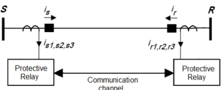
This protection has been used firstly for electrical equipments such as transformers and generators against internal faults. However, in the last years this protection has been used for the protection of transmission lines. However, for the protection of transmission lines a reliable communication channel is required. Fig. 1 shows an example for a transmission line current differential relaying scheme. This scheme consists of two relays at the terminations of the protected line with a communication channel between them.
Fig. 1. Transmission line current differential relaying scheme.
three main steps. First the acquired current signals in each of the line sides are transformed into “αβo” components by applying the Clarke-Concordia transformation. In the second step principal component analysis is performed. Finally, the operation condition of current differential relay system is defined.
Clarke transform is a well-known de-coupling method for three-phase line parameters [10]. The main purpose is obtaining the line currents characteristic representation on
αβ0 space vector. To achieve this, the line currents of the three phase system are measured and transformed using equations (1) and (2). This approach has already been used in power system protection [11].
[ ]
− − − = 2 1 2 1 2 1 2 3 2 3 0 2 1 2 1 1 3 2 C (1)[ ]
= 3 2 1 s s s s o s s i i i C i i i β αand
[ ]
= 3 2 1 r r r r o r r i i i C i i i β α (2)
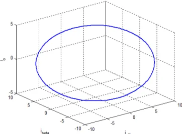
Fig. 2 shows the distribution of the line currents on the αβ0
space for steady state condition. In this condition the current distribution is defined by a circle. For a three phase fault the current distribution in the space is also defined by a circle. However, the circumference related with the three-phase fault is much higher than in steady state condition.
Fig. 2. Distribution of the line currents on the αβ0 space for steady state condition.
Fig. 3 shows the distribution of the line currents on the αβ0
space for a phase to phase short circuit. For this fault type the current distribution is defined by an ellipse. The main orientation of the ellipse is in the αβ axis.
Fig. 3. Distribution of the line currents on the αβ0 space for phase to phase fault.
Fig. 4 shows the distribution of the line currents on the αβ0
space for a single phase to ground fault. In this fault type the current distribution is also defined by an ellipse. However, the main orientation of the ellipse is for the o axis. In this way, the main orientation of the ellipse allows to discriminate between different faults.
Fig. 4. Distribution of the line currents on the αβ0 space for phase to earth fault.
sample matrix of the current signals on the αβ0 space is performed (3). The first sample will be [iα(t0) iβ(t0) i0(t0)],
where t0 denotes the initial time and ∆t the sample interval.
∆ − + ∆ − + ∆ − + ∆ + ∆ + ∆ + = ) ) 1 ( ( ) ) 1 ( ( ) ) 1 ( ( ) ( ) ( ) ( ) ( ) ( ) ( 0 0 0 0 0 0 0 0 0 t n t i t n t i t n t i t t i t t i t t i t i t i t i S o o o β α β α β α (3)
From the correlation matrix of S, denoted by E on (4), its eigenvectors, and respective eigenvalues, can be computed. The eigenvectors and eigenvalues of the correlation matrix are such that (5) holds true for each eigenvector/eigenvalue pair.
S . S
E= T (4)
λ v
Ev= (5)
The obtained eigenvalues will then be used in the transmission channel between the two relays. Since in steady state these values are constant, immunity to problems such as sampling misalignment and time delay of the communication channel will be improved.
Since the obtained patterns are located in a plane, then only the two first eigenvectors are significant. In this way, to discriminate a line fault the eigenvalues (λ1
,
λ2) associated with each eigenvector (eα,
eβ,
eo) are used. So, the equation related with differential currents is defined as can be seen by the following expression:2 2 2 1 2 2 2
1s s r r
diff
e = λ +λ − λ +λ (6)
The relay operation is implemented comparing ediff with the
restraint current er, defined as:
2 2 2 1 2 2 2 1 2 1 r r s s r
e = λ +λ + λ +λ (7)
The differential relay operation is given by:
r op ke
e ≥ (8)
where K is a constant coefficient representing the slope of the relay characteristic. A minimum pick-up current to the relay can also be considered. In this way, the following condition was also considered:
o r
op ke k
e ≥ + (9)
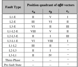
The identification of the faulty phase or phases can be performed by the analysis of the eigenvalues with the
correspondent eigenvector. The discrimination between a phase to phase fault and phase to ground fault will also be performed by the analysis of the eigenvalues with the correspondent eigenvector. From the analysis of the eigenvectors it is possible to identify the position quadrant of the αβo vectors. Table 1 shows the fault classification patterns for each fault type.
Fault Type Position quadrant of ααβααβββ0vectors eαααα eββββ eo
L1-E II V I
L2-E III VI II
L3-E VI II III
L1-L2-E VIII V II
L2-L3-E II I III
L3-L1-E VI VIII I
L1-L2 III II --
L2-L3 II I --
L3-L1 II IV --
Three-Phase -- -- --
Pre-fault State -- -- --
Table 1: Fault classification patterns.
3 Case Study
In this section it will be presented a case study in order to illustrate the effectiveness of the proposed approach. For this study it was used a 520 kV, 500 km transmission line. The simulation and implementation of this system has been done by the Matlab/Simulink software program and the Power System Blockset.
Different fault types have been simulated in order to evaluate the proposed approach. Fig. 5 shows the test result for a three phase short circuit. As expected, the amplitude of the differential currents increases after the short circuit. Figs. 6 and 7 show the time plots of the obtained first and second differential eigenvalues for this fault. As can be seen by these figures the first and second eigenvalues are similar at any time. After the short circuit both eigenvalues increase as the current amplitudes increase, indicating a three-phase fault.
Fig. 6. Obtained first differential eigenvalue before and after a three-phase short circuit.
Fig. 7. Obtained second differential eigenvalue before and after a three-phase short circuit.
Fig. 8 shows the ediff obtained values before and after the three-phase short circuit. As can be seen, these values related with the differential currents present a high increase after the short circuit.
Fig. 8. Obtained values related with the differential currents before and after a three-phase short circuit.
Fig. 9 shows a simulation result for a metallic short circuit fault between two phases. As can be seen after the short circuit the amplitude of the faulty phase’s currents will increase. Figs. 10 and 11 show the correspondent first and second differential eigenvalues for this fault. As can be seen by these figures, after the short circuit the first differential eigenvalue will increase. The second differential eigenvalue almost maintains the same value. This indicaties that the pattern will change from a circle to an ellipse.
Fig. 9. Differential line currents before and after a phase to phase short circuit.
Fig. 10. Obtained first differential eigenvalue before and after a phase to phase short circuit.
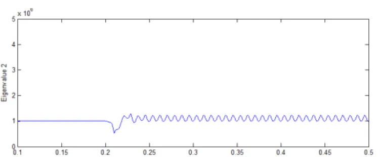
Fig. 11. Obtained second differential eigenvalue before and after a phase to earth short circuit.
Fig. 12 shows the results for a single phase to ground fault. The correspondent first and second differential eigenvalues for this fault type are presented in Figs. 13 and 14. As can be seen, the first differential eigenvalue increases after the fault while the second one almost maintains the same value. From the obtained eigenvectors it is possible to confirm about this fault type, since the main direction of the first differential eigenvalue is the o axis.
Fig. 13. Obtained first differential eigenvalue before and after a phase to ground short circuit.
Fig. 14. Obtained second differential eigenvalue before and after a phase to ground short circuit.
4 Conclusions
In this study an investigation of a novel differential concept for line protection has been introduced. The proposed concept is based on an automatic three step algorithm. First the line currents are obtained. Then a Clarke-Concordia transformation of the current samples is performed. This allows obtaining typical patterns for each fault type. Finally a eigenvector/eigenvalue analysis is performed to obtain the characteristic features. In this way, using the first and second eigenvalues it is possible to define the operation condition of the differential relay operation. From the analysis of the eigenvalues with the correspondent eigenvectors it is possible to identify the fault type. This also allows identifying the faulty phase. The main characteristics and particularities of the proposed approach are the improvement of immunity to problems such as sampling misalignment and time delay of the communication channel. Several simulation results have been presented in order to verify the effectiveness of the proposed approach.
References
[1] M. Tripathy, R.P. Maheshwari, H.K. Verma, “Radial basis probabilistic neural network for differential protection of power transformer”, IET Gener. Transm. Distribution, vol. 2, no. 1, pp. 43–52, (2008).
[2] Y.C. Kang, E.S. Jin, S.H. Kang, P.A. Crossley, “Compensated-current differential relay for protection of transformers”, IEE Proc.-Gener. Transm. Distribution, vol. 151, no. 3, pp. 281–289, (2004).
[3] B. Kasztenny, D. Finney, “New algorithm for generator differential protection”, Eighth IEE International Conference on Developments in Power System Protection, vol. 1, pp. 144–147, (2004).
[4] Tai NengLing, Ai Qian, Yin XiangGen, Chen DeShu, “New generator incomplete differential protection based on wavelet transform”, Electric Power Systems Research, vol. 69, no. 2-3, pp. 179–186, (2004).
[5] J. Wheatley. “A microprocessor-based current differential protection”, in Proc. 4th Int. Conf. Developments in Power System Protection, IEE Conf. Pub. 302, pp. 116–120, (1989).
[6] N. P. Albrecht, W. C. Fleck, K. J. Fodero, R. J. Ince. “Charge comparison protection of transmission lines-communications concepts”, IEEE Transactions on Power Delivery, vol. 7, no. 4, pp. 1853–1859, (1992). [7] Z. Y. Xu, Z. Q. Du, L. Ran, Y. K. Wu, Q. X. Yang, J. L.
He. “A Current Differential Relay for a 1000-kV UHV Transmission Line”, IEEE Transactions on Power Delivery, vol. 22, no. 3, pp. 1392–1399, (2007).
[8] H. Y. Li, E. P. Southern, P. A. Crossley, S. Potts, S. D. A. Pickering, B. R. J. Caunce, G. C. Weller. “A new type of differential feeder protection relay using the global positioning system for data synchronization”,
IEEE Transactions on Power Delivery, vol. 12, no. 3, pp. 1090–1099, (1997).
[9] V. Fernão Pires, Manuel Guerreiro, “A Current Differential Line Protection Using a Synchronous Reference Frame Approach”, The 9th International Conference on Developments in Power System Protection, pp 198-203, (2008).
[10] CV. Jones, “The unified theory of electrical machines”,
New York:Plenum Press, (1967).
[11] L. Sousa Martins, J. F. Martins, V. Fernão Pires, C. M. Alegria, “A Neural Space Vector Fault Location for Parallel Double-Circuit Distribution Lines”,