A Current Differential Line Protection Using a Synchronous
Reference Frame Approach
L. Sousa Martins
*, Carlos Fortunato
*♦, and V.Fernão Pires
* * Escola Sup. Tecnologia Setúbal / Inst. Politécnico Setúbal, Setúbal, Portugal♦
EDP – Energias de Portugal, Lisboa, Portugal
Keywords: Current differential protection, Synchronous reference frame, Park transformation, Line protection.
Abstract
This paper presents a new approach for a current differential protection of the transmission lines. This approach is based on the Park transformation or ABC-dqo transformation. Using the ABC-dqo transformation the three phase quantities are transformed into a synchronous rotating reference frame. In this way, the line currents of the three phase system are measured and transformed into three dc components. So, immunity to problems such as sampling misalignment and time delay of the communication channel will be improved. Several test results are presented in order to show the effectiveness of the proposed approach.
1 Introduction
With the introduction of digital relays, it was possible to implement more effective protection schemes. Some techniques that can be used for digital protection of transmission lines are symmetrical components [1], differential equation algorithm and travelling wave algorithm [2,3]. Furthermore, this technology also allows implementing current differential protection schemes to transmission lines, specially using digital techniques coupled to modern communication links for data transmission.
Current differential relays are widely used for the protection of electrical equipment such as transformers and generators against internal faults. The main reason for using this relay type is due to their simplicity and high sensitivity. So, with the development of digital relays and communication technology, current differential relays have also been used for the protection of transmission lines [4,5,6]. However, when this relay type is applied to transmission lines there are some problems such as sampling misalignment, time delay of the communication channel, line capacitive charging current and errors in current transformers make current comparison difficult to achieve. So, several alternative approaches to conventionally applied current differential relays have been proposed. So, approaches based on composition of the modal voltage and current measurements at both ends [7] and based on the comparison of the integration of current signals under half cycles at both ends [8] have been proposed. The first one presents the advantage of improvement to the relay sensitivity but the misalignment between samples can originate some
problems. The other one presents the solution for the misalignment between samples but depends totally on the zero crossing. Other approaches have been used as a solution for the misalignment between samples problem [9,10,11]. However, in some specific conditions these approaches can cause a fault detection failure [12].
This paper presents a new approach for a current differential protection of the transmission lines. This approach is based on the Park transformation or ABC-dqo transformation in order to transform the three phase quantities into a synchronous rotating reference frame. So, the current measurements at both ends are transformed into a synchronous rotating frame using.
This paper is organized as follows. Section 2 describes the new proposed approach for the current differential protection. In order to show the effectiveness of the proposed methodology several simulation results are presented in section 3. Section 4 presents the conclusions of the work.
2 Proposed current differential line protection
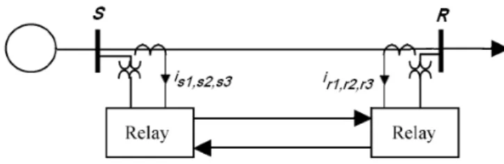
The principle of the current differential line protection rests in the comparison of the sum of the incoming and outgoing currents at the terminations, with a restraint current function depending on the same currents. Local determination of the differential and restraint currents calls for the transmission of currents from the other terminations. Therefore it is required a constant use of transmission channels (Figure 1).
Figure 1: Current differential protection scheme.
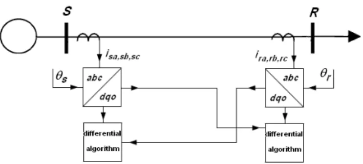
ABC-dqo transformation. Fig. 2 shows the proposed approach for the current differential relay.
Figure 2: Proposed approach for the differential relay.
Using the ABC-dqo transformation the three phase quantities are transformed into a synchronous rotating reference frame. To achieve this, the line currents of the three phase system are measured and transformed into a synchronous rotating frame using the Clarke transformation followed by the rotating matrix. Equations (1) and (2) show the result of those transformations.
=
3 2 1 s s s s o s q s di
i
i
P
i
i
i
and
=
3 2 1 r r r r o r q r d
i
i
i
P
i
i
i
(1) + − + − = 2 1 2 1 2 1 3 2 sin 3 2 sin sin 3 2 cos 3 2 cos cos 3 2 π θ π θ θ π θ π θ θ P (2)The time varying angle θ represents the angular position of
the reference frame which is rotating at constant speed in synchronism with the three-phase ac voltages. The components id and iq represents the resulting current space
vector in the fundamental frequency rotating coordinate system. The dc components of id and iq represent the
positive sequence fundamental.
The used angle θ in the Park transformation to transform
currents
i
s1,2,3 intoi
sdqo is related with the bus S three-phaseac voltages. The angle θ that is used in the Park
transformation to transform currents
i
r1,2,3 intoi
rdqo isrelated with the bus R three-phase ac voltages.
Transformed currents
i
sdqo andi
rdqo are then used in thetransmission channel between the two relays. Since dc
components of id and iq represent the positive sequence
fundamental, immunity to problems such as sampling misalignment and time delay of the communication channel will be improved.
Each of the components of the resulting current space vector in the fundamental frequency rotating coordinate system will be used to discriminate a line fault. So, three differential currents will be obtained, according the dqo components, as can be seen by the following expressions:
−
=
r o r q r d s o s q s d dif o dif q dif di
i
i
i
i
i
i
i
i
(3)Analysing each of the dqo differential currents, it is possible to discriminate the fault type. Here, it will be used the d component to identify any line fault. So, the differential relay operation is implemented comparing iddif with a restraint
current.
The restraining current Ir is defined as:
r d s d
r i i
I = +
2 1
(4)
The operation condition of the differential relay operation is:
r
op kI
I ≥ (5)
where K is a constant coefficient representing the slope of the relay characteristic. To provide a minimum pick-up current to the relay, the following condition was also considered:
o
op k
I ≥ (6)
Therefore, the final definition of the differential relay operation is:
o r
op kI k
I ≥ + (7)
After the relay operation it will be analyzed the o component in order to discriminate between phase to phase fault and phase to earth fault. So, the following condition allows identifying the fault type:
To identify the faulted and un-faulted lines a new transformation will be used. So, currents
i
sdqo andi
rdqo willbe transformed into new quantities by the dqo-ABC transformation or the inverse Park transformation. Equations (9) and (10) show those transformations.
= − s o s q s d s s s i i i P i i i 1 3 2 1
and = −
r o r q r d r r r i i i P i i i 1 3 2 1 (9) + + − − = − 1 3 2 sin 3 2 cos 1 3 2 sin 3 2 cos 1 sin cos 1 π θ π θ π θ π θ θ θ
P (10)
The used angle θ in the inverse Park transformation located
in relay S is related with the bus S three-phase ac voltages, as can be seen by Fig. 3. The angle θ that is used in the Park
transformation located in relay R is related with the bus R three-phase ac voltages.
Figure 3: Proposed approach for the differential relay.
3 Simulation results
The purpose of this section is to illustrate the performance of the proposed current differential relay under different conditions. The presented results are for a 520 kV, 500 km transmission line. This system has been implemented by the Matlab/Simulink software program and the Power System Blockset.
Different types of internal faults are evaluated to verify the effectiveness of the proposed approach. Fig. 4 shows the line differential currents for a three-phase short circuit. As
expected from this result, there is a significant change in the amplitude of the differential currents after the three-phase short circuit.
0.16 0.18 0.2 0.22 0.24 -4000 0 4000 d IA ( A )
0.16 0.18 0.2 0.22 0.24 -4000 0 4000 d IB ( A )
0.16 0.18 0.2 0.22 0.24 -4000 0 4000 t(s) d IC ( A ) 3P
Figure 4: Differential line currents before and after a three phase fault.
Fig. 5 shows the test results of the dqo differential currents for a three-phase short circuit fault. From these results it is possible to verify that those currents are dc components. The amplitude of d component is related with the amplitude of the abc differential currents. Since the d component is related with the active power, this component is fundamental in order to conclude about a line fault. This result also shows that there is a significant change in the d component amplitude before and after the fault. So, this type of fault is easily identified by the analysis of the d component. Since there is not an earth fault, as expected the current differential o component is nearly zero.
0.16 0.18 0.2 0.22 0.24 0 3000 Id ( A )
0.16 0.18 0.2 0.22 0.24 -1000 0 2000 Iq ( A )
0.16 0.18 0.2 0.22 0.24 -20 0 20 t(s) Io ( A ) 3P
Figure 5: Differential line currents after ABC-dqo transformation before and after a three phase fault.
0.3 0.32 0.35 0.38 0.4 -3000
0 3000
d
IA
(
A
)
0.3 0.32 0.35 0.38 0.4
-3000 0 3000
d
IB
(
A
)
0.3 0.32 0.35 0.38 0.4
-3000 0 3000
t(s)
d
IC
(
A
)
PP
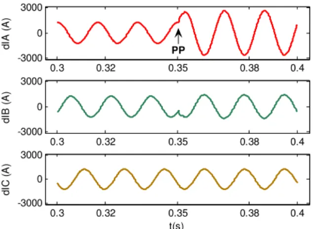
Figure 6: Differential line currents before and after a phase to phase fault.
The differential line currents after ABC- dqo transformation before and after a phase to phase fault are presented in Fig. 7. From this result it is possible to verify that those currents present a similar result then the three-phase short circuit. In fact, after the short circuit fault between phase a and b there is a suddenly change in d and q components. The amplitude of the d component increases and the q component decreases after the fault. This is expected since the d component is related with the active power the q component is related with the reactive power. However, in this case, after the short circuit the dq differential currents present a dc and an ac component. This indicates that the system it is not equilibrated. So, since the current differential o component is nearly zero and there is an ac component a phase to phase fault it is clearly identified.
0.3 0.33 0.35 0.38 0.4
0 1500
Id
(
A
)
0.3 0.33 0.35 0.38 0.4
0 1500
Iq
(
A
)
0.3 0.33 0.35 0.38 0.4
-50 0 50
t (s)
Io
(
A
)
PP
Figure 7: Differential line currents after ABC-dqo transformation before and after a phase to phase fault.
Internal phase to earth faults were also simulated. Fig. 8 shows the differential line currents before and after for a short circuit fault between phase a and earth. From this result, it is possible to verify that there is a change in the amplitude of the phase a differential.
0.16 0.18 0.2 0.22 0.24 0.26 -2000
0 2000
d
IA
(
A
)
0.16 0.18 0.2 0.22 0.24 0.26 -2000
0 2000
d
IB
(
A
)
0.16 0.18 0.2 0.22 0.24 0.26 -2000
0 2000
t(s)
d
IC
(
A
)
PN
Figure 8: Differential line currents before and after a phase to earth fault.
Fig. 9 shows the test results of the dqo differential currents before and after for a short circuit fault between phase a and earth. This result shows that dq components present a significant change. Again, the amplitude of the d component increases and the q component decreases after the fault. So, all fault types can easily be identified by the analysis of the d component. However, in this fault type (phase to ground fault) the current differential o component is not anymore nearly zero, presenting now a significant ac component. So, by the analysis of the o component it possible to easily identify earth faults.
0.16 0.18 0.2 0.22 0.24 0.26 0
500 1000
Id
(
A
)
0.16 0.18 0.2 0.22 0.24 0.26 500
1000 1500
Iq
(
A
)
0.16 0.18 0.2 0.22 0.24 0.26 -500
0 500
t(s)
Io
(
A
)
PN
Figure 9: Differential line currents after ABC-dqo transformation before and after a phase to earth fault.
differential current for a no fault situation. On other hand, the operating characteristic is always smaller than the d component of the differential current for a fault situation.
Figure 10: Effect of fault resistor variation on the percentage differential characteristic.
In several digital transmission line protection based on current differential, the sampling at the ends of the transmission line is unsynchronized. Therefore the samples from the two transmission line ends may not be aligned. As a consequence, instability of the protection scheme could be happen [8]. However, in this methodology this is not critical. This can be illustrated by an example of a phase to phase fault and a time delay of the transmitted signals. So, in Fig. 11 it is illustrated the d component of the differential currents for a phase to phase fault with and without time delay of the transmitted signals. In this case it was used a time delay of 2 ms and 10 ms. As can be seen by this figure, the time delay of the transmitted signals does not present any problem for the stability of the proposed protection scheme.
!
"
Figure 11: Proposed approach for the differential relay.
4 Conclusions
An investigation of a new approach for a current differential protection of the transmission lines was presented and analyzed. In this new approach Park transformation or ABC
-dqo transformation has been used. Using this concept the three phase quantities are transformed into a synchronous rotating reference frame. This will transform the three phase line currents into three dc components. Therefore, immunity to problems such as sampling misalignment and time delay of the communication channel will be improved. For the differential characteristic it is only required to analyse the d component of the differential line currents. The effectiveness of the proposed approach was analyzed by several simulation results.
References
[1] A. G. Phadke, M. Ibrahim, T. Hlibka. “Fundamental Basis for Distance Relaying with Symmetrical Components”, IEEE Transaction on Power Apparatus and Systems, Vol. PAS-96, No. 2, March/April, pp. 635-646, (1977).
[2] M. Akke, J. T. Thorp. “Some Improvements in the Three-Phase Differential Equation Algorithm for Fast Transmission Line Protection”, IEE Proc.-Gener. Transm. Distribution, vol. 140, no. 1, pp. 37–47, (1993). [3] M. H. J. Bollen. “Travelling-Wave-based Protection of Double-Circuit Lines”, IEEE Transactions on Power Delivery, vol. 13, no. 1, pp. 66–72, (1998).
[4] J. Wheatley. “A microprocessor-based current differential protection”, in Proc. 4th Int. Conf. Developments in Power System Protection, IEE Conf. Pub. 302, pp. 116–120, (1989).
[5] N. P. Albrecht, W. C. Fleck, K. J. Fodero, R. J. Ince. “Charge comparison protection of transmission lines-communications concepts”, IEEE Transactions on Power Delivery, vol. 7, no. 4, pp. 1853–1859, (1992). [6] Z. Y. Xu, Z. Q. Du, L. Ran, Y. K. Wu, Q. X. Yang, J. L.
He. “A Current Differential Relay for a 1000-kV UHV Transmission Line”, IEEE Transactions on Power Delivery, vol. 22, no. 3, pp. 1392–1399, (2007).
[7] R. K. Aggarwal, A. T. Johns. “A differential line protection scheme for power systems based on composite voltage and current measurements”, IEEE Transactions on Power Delivery, vol. 4, no. 3, pp. 1505– 1602, (1989).
[8] L. J. Ernst, W. L. Hinman, D. H. Quam, J. S. Thorp. “Charge comparison protection of transmission lines— relaying concepts”, IEEE Transactions on Power Delivery, vol. 7, no. 4, pp. 1835–1852, (1992).
[9] IEEE Committee Report. “Synchronized sampling and phasors measurements for relaying and control”, IEEE Transactions on Power Delivery, vol. 9, no. 1, pp. 442– 452, (1994).
[10] J. Lambert, A. G. Phadke, D. M. Nabb. “Accurate voltage phasor measurement in a series compensated network”, IEEE Transactions on Power Delivery, vol. 9, no. 1, pp. 501–509, (1994).
IEEE Transactions on Power Delivery, vol. 12, no. 3, pp. 1090–1099, (1997).