Waveguide E-Plane All-Metal Inserted Diplexer
M. Raki
ć
1, B. Jokanovi
ć
1, Dj. Budimir
2Abstract: This paper presents the procedure for designing a waveguide E-plane diplexer for Ku band with inserted metal septa. The diplexer is designed with fil-ters of the fifth order and with T-junction in E-plane for the purpose of easier in-tegration with microwave transceiver. The aim of this work is to master the design of a diplexer that should obtain 60 dB insulation between receiver and transmitter of a radio link and that will not need to be adjusted in serial production.
Keywords: Waveguide, Diplexer.
1 Introduction
The advantage of waveguide filters over the planar structures is their Q-factor (around 500 at 30 GHz), which enables a satisfactory filter slant. Disadvantage is their volume, which is why the lowest possible filter order is desirable. Such filters have low losses. Low production costs make them additionally suitable for serial production. Strong coupling between resonators even more increases the Q-factor [1], making these filters suitable for narrow, few-percent, bandwidths [2].
Adjustment of filters in serial production is avoided by use of electromagnetic simulators in their precise designing. This is possible with waveguide E-plane filters with inserted metal septa as resonators are made by photolithographic procedure, which is much more precise than mechanical make. Also, the costs of expensive equipment and the time needed for production are reduced.
This paper offers design of input filters for radio link at 13 GHz operating at 155 Mbit/s, as per ITU-R recommendation F.497-6 [3], Fig. 1. Distance between receiving and transmitting frequency is 266 MHz. The diplexer is designed for fifth channel. Lower subrange of first channel is at 12.877 GHz and higher is at 13.143 GHz. If receiver of a device is operating at lower subrange, then transmitter of the same device is operating at higher subrange, and the other way round. In front of each receiver and transmitter there is a filter, which has to suppress the signal at the other frequency [4], Fig. 2. Insulation of 60 dB should be provided between the receiving and the transmitting signal. Due to such strict insulation requirement, it is necessary that a compromise should be made between the filter length and insertion loss in bandstop.
Required diplexer consists of a lower and an upper filter. The lower filter has the following characteristics: central frequency of 12.877 GHz, 1 dB pass-band around 100 MHz, attenuation lesser than 1.0 dB and S11 below – 15 dB, and at 13 GHz stop-band
attenuation higher than 60 dB. The upper filter has central frequency of 13.143 GHz, the same pass-band characteristics and at 13.07 GHz stop-band attenuation is higher than 60 dB.
Fig. 1- Channel order according to Alternative I ITU-R recommendations F.497-6.
Fig. 2 - Diagram of microwave transceiver with a diplexer.
2 A Waveguide E-Plane Filter with Metal Septa
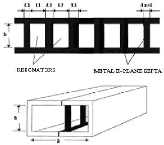
The filter consists of a metal septa placed at the maximum of the electric field for TE10 in E-plane. The septa are metal inductive quadrangular diaphragms coupling
half-wave resonators [5], Fig. 3.
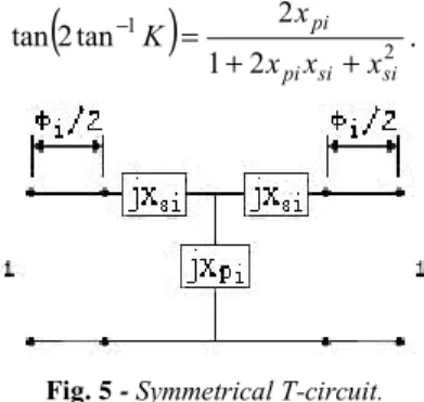
Standardized equivalent diagram of this filter for dominant TE10 mode may be
rep-resented by diagram in Fig. 4, where standardized reactances xsiand xpiare functions of
diaphragm length di[6].
Fig. 3- Structure of E-plane band-pass filter with septa.
Fig. 4- Standardized equivalent circuit for dominant mode.
Then coupling of higher order modes between adjacent diaphragms is neglected. An impedance inverter represented by symmetrical T-circuit in Fig. 5 represents each diaphragm. Sum
(
Φi+Φi+1)
2 determines electrical length of the resonator. When Φi is(
pi si)
( )
sii x x x
1 1
tan 2
tan− + − −
− =
Φ , (1)
standardized ABCD matrix of T-circuit gained the following shape
0 j
j 0
K K
,
(
)
2 1 2 1 2 tan 2 tan si si pi pi x x x x K + + =− . (2)
Fig. 5 - Symmetrical T-circuit.
Such defined K has nonlinear frequency dependence and is not constant. Applying afore mentioned expressions, resonator length li and metal septum length di are counted at central frequency of desired pass-band. Standard Chebyshev’s attenuation characteristic is modified by linear dependence of discontinuity from frequency and mathematically can be described as follows,
λ λ π λ λ + = g 0 g 0 g g 2 2 sin 1 log
10 h T a
LI n , (3)
where Tn
( )
x are Chebyshev’s polynomials of the first kind,( )
x(
n x)
Tn =cos cos−1 , 0≤x≤1, (4)
and
( )
x(
n x)
Tn1 cos
cosh −
= ,x ≥1. (5)
Parameter n is a filter order, h determining attenuation variation in pass-band, and
α determining pass-band width. λg0 is wavelength in a waveguide at central frequency,
and λg is wavelength in a waveguide at the frequency of interest. Minimal pass-band
reflexion is defined as follows,
+ 10
= 10 2
1 1 log
h
LR . (6)
This approximation method may result in considerably shifted pass-band in relation to required value and then further optimisation is needed. Correction of pass-band sug-gested by Lim, Lee, and Itoh [7] takes into consideration nonlinear frequency depend-ences of the metal septa impact.
fre-quency counting pace, number of modes, waveguide dimensions and septa thickness. The synthesis gives filter order n , resonator length liand metal coupling length di
3 Electromagnetic Analysis
a) Analysis of Upper and Lower Filters
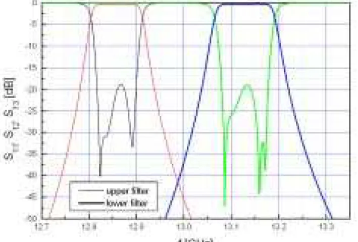
Filters have been analysed in HFSS program package and their responses are shown in Fig. 6. Resonator lengths are slightly corrected in comparison to those obtained by EPFIL program package in order to obtain pass-band S11 lesser than - 18 dB. Lower filter central frequency is 12.856 GHz, width of 1 dB pass-band is 98 MHz, while at-tenuation at 13.064 GHz, at the point of lower limit of 1 dB upper filter pass-band is 64 dB. Central frequency of upper filter is 13.127 GHz, width of 1 dB pass-band is 115 MHz, while attenuation at 12.905 GHz, where upper filter has 1dB attenuation, is 61 dB.
Fig. 6 - Responses of lower and upper filters obtained by HFSS program.
b) Analysis of diplexer
Fig. 7 - Cross section of diplexer in E-plane.
Diplexer obtained in this manner has a very bad reflection, especially at low band, which is degraded for about 10 dB. Characteristic of
21
S has been degraded too, which means that in further optimisation it is necessary that lower filter dimensions should be corrected.
Fig. 8- Response of diplexer after optimisation optimisation of Ld and Lg lengths.
4 Measurement Method
Fig. 9 - TRL calibration in waveguide.
perform calibration of the network analyser. Traditionally, the method for full calibration of two ports uses tree standards for impedance and one transmission standard. Usually used standards are: short, open, 50 Ω load and true standards. Such calibration is usually referred to as SOLT calibration.
In case of not having the calibration standards with connectors of the same type as on the measuring instrument, it is necessary to design and characterize new standards. Instead of four SLOT calibration standards, it is easier to make three standards necessary for TRL calibration as suggested by Engen and Hoer in 1979 [9]. As shown in Fig. 9, this calibration uses true, reflect and line standards, which are much easier to make in waveguide technique than the SOLT calibration standards [10].
5 Measurement Results
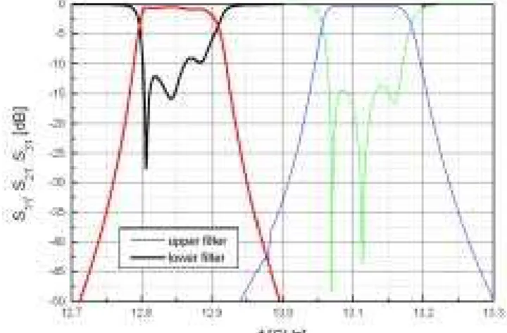
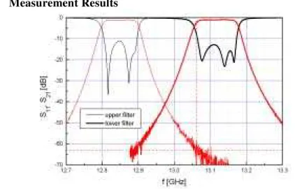
Fig. 10- Measured responses of upper and lower filters.
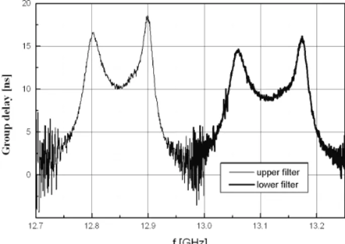
Fig. 10 shows measured responses of lower and upper filters. Both filters have de-graded reflection in pass-band, 5 dB for upper and 8 dB for lower filter. Fig. 11 shows group delay of both filters. The figure clearly shows that the upper filter has better char-acteristic of group delay.
Fig. 11-Group delay of lower and upper filters.
6 Conclusions
Waveguide filters for Ku band that are included in the diplexer filter for radio link at 13 GHz are designed. Filters of the fifth order with metal septa in E-plane are realized. Characteristics of realized filters are in good agreement with designed ones as for the central frequency and required attenuation in stopband. However, reflection in pass-band has been increased for 5 dB - 8 dB. Diplexer filter is so designed that by choosing distance between T-junction and the filter reflection is minimized. With L distances so optimised, it has been theoretically shown that the diplexer characteristic, as far as the reflection is concerned, additionally degrades in comparison to characteristics of the filters themselves. This is why it is necessary that the filter should be redesigned so that they have initial reflection of at least – 25 dB.
Acknowledgements
This paper is partially financed by the Serbian Ministry of Science and Environmental Pro-tection within projects PTR-2002.B and IT.1.17.0196.B.
6 References
[1] Bui L. Q., Ball D., Itoh T.: Broad-Band Millimeter-Wave E-Plane Bandpass Filters, IEEE Trans. Microwave Theory & Tech., 32:1655-1658, 1984.
[2] Shih Y. C.: Design of Waveguide E-Plane Filters with All-Metal Inserts, IEEE Trans. Microwave Theory & Tech., 32:695-704, 1984.
[3] Recommendation ITU-R F.497-6, Radio-frequency channel arrangements for radio-relay systems operation in the 13 GHz frequency band, 1999.
[5] Budimir Dj.: Generalized Filter Design by Computer Optimization, Artech House, Boston, 1998.
[6] Postoyalko V., Budimir D. S.: Design of Waveguide E-Plane Filters with All-Metal Inserts by Equal Ripple Optimization, IEEE Trans. Microwave Theory & Tech., 42:217-222, 1994.
[7] Lim J. B., Lee C. W., Itoh T.: An Accurate CAD Algorithm for E-Plane Type Band-pass Filters Using a New Passband Correction Method Combined With the Synthesis Procedures, IEEE MTT-S Int. Microwave Symp. Dig., 1179-1182, 1990.
[8] EPFILTER, Software and User’s Manual, Tesla Communications Limited, London, England.
[9] Engen G. F., Hoer C. A.: Thru-Reflect-Line: An Improved Technique for Calibrating the Dual Six-Port Automatic Network Analyzer, IEEE Trans. Microwave Theory & Tech., 27:987-993, 1979.