Design and Synthesis of Quasi Dual-mode,
Elliptic Coaxial Filter
Sovuthy CHEAB, Peng Wen WONG
Dept. of Electrical and Electronic Engineering, University of Technology Petronas, 326100, Tronoh, Perak, Malaysia
[email protected], wong [email protected]
Abstract. This article introduces the design of a novel quasi dual-mode, elliptic coaxial filter. The transfer function is mapped to a Generalized Chebyshev prototype with sym-metrically located transmission zeros (TZs) where the cou-pling values are extracted. Furthermore, the miniaturiza-tion is achieved by incorporating stepped-impedance coax-ial line with inductive element shunted at the center to ex-hibit a quasi dual-mode property. Theoretical analysis to-gether with experimental prototype is presented. The center frequency of the filter is 2.7 GHz. The simulated and mea-sured insertion loss/return loss are 1.2 dB / 15 dB and 2.5 dB / 11.5 dB respectively. Both theoretical and measured results show a very good agreement.
Keywords
Bandpass filter, coaxial filter, elliptic, quasi dual-mode, source-load coupling
1. Introduction
Microwave filter with compact size, low weight, low loss, and high power handling and selectivity is demanded specifically in cellular communications base-stations. With these stringent requirements, the planar based microstrip fil-ter [1], [2], [3], [4] cannot be used due to its inherent low Q-factor. The most suitable transmission line for this appli-cation is coaxial transmission line for its capability of larger usable bandwidth, smaller size and highQ-factor with TEM wave propagation. However, to date the conventional coaxial filter developed could achieve only one resonance per physi-cal structure [5], [6]. This single mode technology based on combline filters are widely employed in base station [7]. The major disadvantage associated with the conventional single mode technology is the relatively large filter size and high material cost. Until recently the attempt to realize two res-onances and dual bands response using coaxial had been reported based on combline topology [8]. The structure is made up of three metallic conductors: the inner and the inter-mediate conductors and the enclosure. The two resonances achieved have to be dual bands due to the limitation of the coupling of the resonator structure.
In terms of selectivity, elliptic and pseudo-elliptic fil-ters offer optimal solutions to filtering function with high selectivity and low in-band insertion loss. This is achieved by shifting the TZs of an N-degree filter network from in-finite frequencies to in-finite frequencies. This article presents the design of quasi dual-mode, elliptic coaxial bandpass fil-ter. As miniaturization is one of the key requirements for a filter, a novel stepped impedance dual mode resonator is adopted where a compact design is shown. A prototype is realized and presented in this paper to demonstrate the fea-sibility of the approach. It will be shown that it is possible to have two resonances for one physical resonator structure for coaxial TEM line. Moreover, the source-load coupling gives additional two transmission zeros (TZs) beyond the passband which offers a quasi-elliptic response.
The organization of this paper is as follows: Section 2 describes a brief theory of quasi-dual mode, elliptic filter in-cluding the mapping of the transfer function to the General-ized Chebyshev prototype. Section 3 discusses the coaxial prototype design together with result analysis. Finally, Sec-tion 4 is the conclusion.
2. Theory
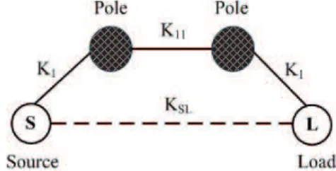
Depicted in Fig. 1 is the coupling and routing structure of dual mode resonator with source-load coupling whereK1, K11, andKSLare the inverters.
Fig. 1.Coupling and routing structure.
The low-pass section comprises of two capacitorsC1andC2 with an inverterK11in between. The two resonators are cou-pled to the source or load by an inverterK1.KSLis introduced
to form the source-load coupling. The circuit model of the upper path of Fig.1 is shown in Fig.2.
Fig. 2.Circuit model of the low-pass dual mode resonator (with-out source-load coupling).
Assuming that the capacitorC1=C2=1 F, the cascading elements in Fig. 2 builds up the transfer matrix as
T1= ⎡
⎢ ⎢ ⎢ ⎣
ωK11 j
−K
2 1
K11
+K21ω2K
11
−jK11 K12
ωK11
⎤ ⎥ ⎥ ⎥ ⎦ . (1)
Note that jis used in this paper to denote the imaginary unit of a complex number which is the square root of -1. The correspondingYmatrix is
Y1= ⎡
⎢ ⎢ ⎢ ⎣
−jωK112
K12−1+ω2K112
jK11
K12−1+ω2K112
jK11
K12
−1+ω2K
112
−jωK112
K12
−1+ω2K
112 ⎤ ⎥ ⎥ ⎥ ⎦ . (2)
The transfer matrix of the lower path of Fig. 1 (source-load coupling) is
TSL=
⎡
⎣
0 jKSL j
KSL
0
⎤
⎦. (3)
The correspondingYmatrix is
YSL=
⎡ ⎢ ⎢ ⎣ 0 j KSL j KSL 0 ⎤ ⎥ ⎥ ⎦ . (4)
The totalYmatrix is
YT =Y1+YSL. (5)
The conversion between two-port network parameters table in [9] is used to convert fromYtoS-parameter. Finally, the transfer function of the network is
|S12(jω)|2=4
γ2ω2+γ0 ρ2ω2+ρ1ω+ρ0
2 (6) where
γ0=K12K11KSL−K12
KSL, (7)
γ2=K14K112KSL, (8)
ρ0=−2K11KSLK12+KSL2K14+K14+K112KSL2, (9)
ρ1=2jKSL2K12K112, (10)
ρ2=−K14K112−KSL2K14K112. (11)
Now consider the transfer function for a lossless pas-sive filter network which is defined as
S12(jω)
2
= 1
1+ε2F2
N(ω)
(12)
whereεis a ripple constant andFN(ω)represents a filtering
or characteristic function. The expression ofFN(ω)is given
by [10]
FN(ω) =
1 2
N
∏
r=1
(αn+βn) + N
∏
r=1
(αn−βn)
(13)
where
αn=
ω− 1
ωn
1− ω ωn
−1
, (14)
βn=
(ω2−1)
1− 1 ωn2
1− ω ωn
−1
. (15)
N is the degree of filter, andωnis the position of the n-th
TZ in the complex frequency plane. Therefore, the filtering function of the second-order Generalized Chebyshev filter prototype with 15 dB return loss level and two symmetri-cally placed TZs at±j5 is
FN(ω) =
49ω2−25
−ω2+25. (16)
The filtering function of the quasi dual-mode, elliptic filter is derived from (6) as
fN(ω) =k
a
2ω2+a0 b2ω2+b0
(17)
wherek=1.2 is the normalizing constant and
a0=2.7K1 4+K
112KSL2−2K11KSLK12−KSL2K14, (18)
a2=2.7K1 4K
112KSL2−1, (19)
b0=K11KSL−1.0K1 2
KSLK12, (20)
b2=K14K112KSL. (21)
It should be noticed that the source-load coupling is introduced so that the filtering function can form a fraction which enables the generation of the finite-frequency TZs at both sides of the passband. The mapping givesK1=0.831, K11=0.552, andKSL=−8.276. The transfer function of
the quasi-elliptic dual-mode network expressed in (6) then becomes
1 11 11 1 1
1 11
11 1 1
|S12(jω)|2=
0.012754ω 4−0
.63771ω 2+7
.9714 ω4−1
.6372ω 2+8
.1280
, (22)
and its corresponding reflection function is
|S11(jω)|2= ω4−1
.020408163ω 2+0
.2603082049 ω4−1
.637235378ω2+8.128002235 .
(23)
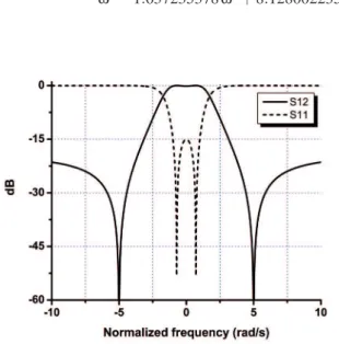
Fig. 3.Normalized frequency responses.
The normalized frequency responses in dB of the transfer and reflection function for two paths is illustrated in Fig. 3 where the passband return loss is 15 dB and the two poles within the passband and two TZs in the stopband are clearly shown.
3. Coaxial Prototype
The quasi dual-mode, elliptic TEM coaxial bandpass filter prototype has been fabricated using solid aluminum filled by the air as the dielectric. Fig. 4 depicts the structure layout of the filter prior to fabrication using CNC machine whereas Fig. 5 gives the physical dimensions of the coaxial filter prototype after correcting the capacitive coupling be-tween the input/output to the resonator.
Fig. 4.The structure layout of quasi dual-mode, elliptic coaxial filter.
Fig. 5.Physical dimensions. (Unit: millimeters).
Fig. 6.Simulation transmission and reflection responses.
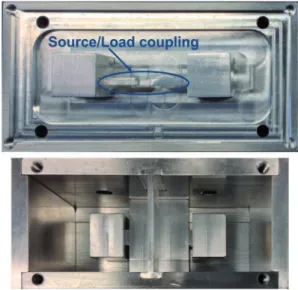
Figure 6 shows the simulated response of quasi dual-mode, elliptic coaxial filter using ANSYS HFSS [11]. The fabri-cated coaxial bandpass filter prototype is shown in Fig. 7. The bandpass filter is smaller in size due to the use of the stepped-impedance but with the expense of itsQ-factor reduction. Based on the graph in [12], the Q-factor of the stepped impedance resonator is reduced by 15% if the impedance ratio is 1.3. Hence the resultingQ-factor is only 2450.
Ref. Resonator structure No. of resonances Q Selectivity TZ [13] Combline (coax) 1 (per unit structure) High High No [14] Combline (coax) 1 (per unit structure) High High Yes [15] Dual-mode (coax) 2 (per unit structure) High High No [16] Dual-mode (planar microstrip) 2 (per unit structure) Low Moderate Yes This work Quasi dual-mode, elliptic (coax) 2 (per unit structure) High High Yes
Tab. 1.Comparison of state-of-the-art.
the stub to achieve the source-load coupling gives rise of two finite-frequency TZs on both sides of the passband as pre-sented. The location of these TZs can be easily controlled by changing the dimension of this stub used for the source load coupling.
The comparative study of the main features of the pro-posed quasi dual-mode, elliptic coaxial filter with the state-of-the-art is given in Tab. 1.
Fig. 7.Quasi dual-mode, elliptic coaxial filter prototype.
Fig. 8.Measured transmission and reflection responses.
4. Conclusion
In this article, a novel technique to construct a quasi dual-mode coaxial bandpass filter is introduced. The minia-turization is obtained by incorporating stepped-impedance coaxial line with inductive element shunted at the center to exhibit a quasi-dual mode property. The experimental proto-type is fabricated and shown. The measured results show the two resonances in the passband. It was successfully demon-strated that the filter can achieve a quasi dual-mode, elliptic response with two transmission zeros and two transmission poles. The experimental work shows a good agreement with the theory.
References
[1] HONG, J. S., LANCASTER, M. J. Microstrip Filters for RF/Microwave Applications. John Wiley & Sons, Inc. 2001. [2] BARAL, R. N., SINGHAL, P. K. Recent techniques in design and
implementation of microwave planar filters.Radioengineering, 2008, vol. 17, no. 4, p. 392–396.
[3] VAGNER, P., KASAL, M. A novel bandpass filter using a combina-tion of open-loop defected ground structure and half-wavelength mi-crostrip resonators.Radioengineering, 2010, vol. 19, no. 3, p. 392– 396.
[4] DURAN-SINDREU, M., VELEZ, P., BONACHE, J., MARTIN, F. Broadband microwave filters based on open split ring resonators (OSRRs) and open complementary split ring resonators (OCSRRs): Improved models and design optimization.Radioengineering, 2011, vol. 20, no. 4, p. 775–784.
[5] MATTHAEI, G. L., YOUNG, L., JONES, E. M. T. Microwave Filters, Impedance-Matching Networks, and Coupling Structures.
Artech House, Norwood, MA, 1980.
[6] MATTHAEI, G. L. Comb-line bandpass filters for narrow or moder-ate bandwidth.Microwave Journal, 1963, vol. 6, p. 82–91. [7] MANSOUR, R. R. Filter technologies for wireless base stations.
IEEE Microwave Magazine, 2004, vol. 5, no. 1, p. 68–74. DOI: 10.1109/MMW.2004.1284945.
[8] RUIZ-CRUZ, J. A., FAHMI, M. M., MANSOUR, R. R. Dual-resonance combline resonator for dual-band filters. InIEEE MTT-S International Microwave MTT-Symposium Digest (MTT). Montreal (Canada), 2012 , p. 1–3. DOI: 10.1109/MWSYM.2012.6259436
[9] POZAR, D. M.Microwave Engineering. John Wiley, 2000, p. 187. [10] CAMERON, R. J., KUDSIA, C. M., MANSOUR, R. R.Microwave
Filters for Communication Systems: Fundamentals, Design and Ap-plications. New Jersey: John Wiley & Sons, 2007.
[11] HFSS, 3D Full Wave Electromagnetic Field Simulation, Ansoft De-signerR.
[12] MAKIMOTO, M., SADAHIKO, Y. Corrections to compact bandpass filters using stepped impedance resonators.Proceeding of the IEEE, 1979, vol. 67, no. 11, p. 1568, DOI: 10.1109/PROC.1979.11521
[13] SH-ASANJAN, D., MANSOUR, R. R. A novel coaxial resonator for high power applications. In 44thEuropean IEEE MTT-S
Interna-tional Microwave Conference (EuMC). Rome (Italy), 2014, p. 295– 298. DOI: 10.1109/EuMC.2014.6986428
[14] WOLANSKY, D., TKADLEC, R. Coaxial filters optimization using tuning space mapping in CST Studio.Radioengineering, 2011, vol. 20, no. 1, p. 289–294.
[15] CHEAB SOVUTHY, WONG, P. W. Stepped impedance dual mode coaxial filter. In IEEE International RF and Microwave Conference (RFM). Penang (China), 2013, p. 165–167. DOI: 10.1109/RFM.2013.6757240
[16] ATHUKORALA, L., BUDIMIR, D. Compact dual-mode open loop microstrip resonators and filters. IEEE Microwave and Wireless Components Letters, 2009, vol. 19, no. 11, p. 698–700. DOI: 10.1109/LMWC.2009.2032003
About the Authors . . .
Sovuthy CHEAB was born in Battambang, Cambodia, in 1986. He received his B.Eng. (Honors) degree and M.Sc degree in Electrical and Electronics both from Univer-siti Teknologi PETRONAS, Malaysia respectively in 2011 and 2012. He is currently working towards the Ph.D. degree in Microwave Engineering at Universiti Teknologi PETRONAS, Malaysia. His research interests include in-cludes passive microwave filters in planar and cavity design.
Peng Wen WONGwas born in Perak, Malaysia, in 1984. He received the B.Eng. (Hons. First-Class) degree from Uni-versity of Leads in 2005 in Electrical and Electronic Engi-neering. He then joined Intel Malaysia and worked as a Test R&D engineer. He received research funding from Ministry of Defense, UK where he completed his Ph.D. in University of Leads in 2009. He is currently a senior lecturer in Uni-versiti Teknologi PETRONAS at the department of Electri-cal and Electronic Engineering, , teaching electromagnetism and microwave engineering subjects. His research interest includes passive and active microwave filters. He also inves-tigates the applications of microwaves in biology.