Vol. 4, No. 2, November 2007, 147-159
Fuzzy Control of Induction Motor
with Reduced Rule Base
Pradeep Chatterjee
1, B.M. Karan
2, P.K. Sinha
3Abstract: Several methods have been proposed and published for control of induction motors. The objective of this work is to develop a fuzzy controller with reduced rule base. Using concepts of direct torque control, a fuzzy controller has been designed with a cascaded final state selector, which reduced rule base and gave birth to a new control technique of induction motor. Details and perfor-mance of the fuzzy controller has been discussed in the paper.
Keywords: Induction motor, Fuzzy logic, Direct torque control.
1 Introduction
For last two decades researchers are working on development of AC. drives to control speed and torque of induction motors. Their efforts in this field are justified, as induction motor is one of the cheapest and robust motors available to the industry today. Suitable design of AC. drives for induction motor can transform the nonlinear torque-speed characteristics of induction motor to constant torque-speed characteristics similar to that of a DC. motor. Develop-ment of AC. drives for induction motors started with variable frequency control followed by vector control and recently leading to direct torque control using space vector modulation [1]. Here Application Specific Fuzzy Switching (ASFS) has been designed for direct torque control of squirrel cage induction motor, so space vector modulation for direct torque control shall be dealt subsequently.
Variable frequency control is simple to design and implement and even offers the advantage of operating without an encoder. Control is generated by maintaining constant volts per hertz output; used to drive a pulse width modulated (PWM) circuit. Since torque and flux are neither directly nor indirectly controlled, it results in limited speed accuracy and poor torque control.
To overcome this limitation, vector control used the concept of vectorizing voltage and current into two orthogonal axes (d-axis and q-axis) so as to control flux and torque independently similar to that of a DC. motor control. This results
in good torque response and inclusion of an encoder increases accuracy of speed and torque, disadvantage being mandatory inclusion of an encoder. Moreover, the PWM modulator processes voltage and frequency reference outputs of the vector control stage thereby creating a signal delay between the input references and resulting stator voltage vector produced. This limits achievement of very rapid flux and torque control.
2
Direct Torque Control with Space Vector Modulation
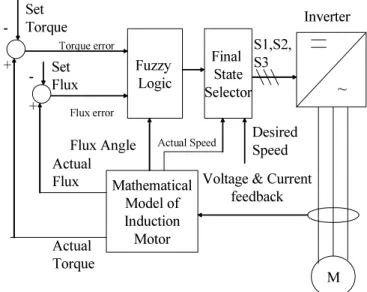
Concepts of direct torque control have been explained in [1, 3]. Direct torque control (DTC) combines field-oriented control, digital signal processing and application specific integrated circuit. The control blocks associated are mathematical model of induction motor observer, hysteresis controller and ASIC for optimal switching. The mathematical model of induction motor observer estimates actual torque and flux of the motor from current and voltage feedback. Reference/desired values of torque and flux are fed to the hysteresis controller. Torque and flux comparators in hysteresis controller compare actual torque and actual flux with their respective desired values. If actual torque is below its differential hysteresis limit, the torque status goes high and if it is above its differential limit the torque status goes low. Similarly flux status goes high or low depending on actual flux value is below or above it’s differential limit. Torque and flux status are fed to ASIC, which decides the switching state to be selected and accordingly switches it.
~ M Mathematical Model of Induction Motor
Voltage & Current feedback Fuzzy Logic Actual Flux Actual Torque S1,S2, S3 Inverter Set Torque Set Flux Torque error Flux error -+ + -Flux Angle Final State Selector Desired Speed Actual Speed
The biggest drawback of direct torque control is that ASIC switching is not optimal switching. This would be clear if we consider a particular case. Suppose torque and flux levels are below their differential hysteresis limits. So say, switching state 2, as shown in Fig. 2 is optimal selection so that both torque and flux increases simultaneously. At an instant of time torque reaches it’s lower differential limit (which is supposed to be desired torque) but flux level is still below. Since torque level has not reached upper hysteresis limit, torque status has not yet changed and so switching state 2 continues to be selected. This results in unwanted increase in torque and partial increase in flux till actual torque reaches upper hysteresis limit. Instead, say, switching state 1 would have been optimal selection of switching under such condition. There can be several such instances where optimal switching may fail with hysteresis controller and ASIC switching [2]. In such cases fuzzy logic with its linguistic capability decides optimal switching states for better control.
Several works have been reported on design of fuzzy controllers for induction motor control. In some works [10] DTC rules have been replaced with fuzzy rules. Chiraz et al [11] discussed design of fuzzy controller to address undesirable torque and current distortion caused by basic DTC. Efforts are evident to determine Kp and KI for PI regulator using fuzzy logic [12]. Deflection
angle of stator flux is derived from torque and flux errors using fuzzy inference method [13]. Fuzzy logic controller based on space vector modulation has been designed to address problem of drop of stator flux while stator flux vector changes position from one sector to another sector [14].
Moreover, for direct torque control, two different sets of switching states are selected for clockwise and counterclockwise rotation of induction motor. With the new designed technique, both have been combined in one set of switching states by design of the fuzzy controller cascaded with the final state selector. This helped in reducing total number of fuzzy rules thereby improving pro-cessing time for real time control application. The new induction motor controll-ler has been designed as shown in block diagram in Fig. 1.
3
New Control Technique of Induction Motor with Fuzzy Logic
Three inputs have been considered for the fuzzy controller i.e. torque error, flux error and flux angle. Inverter vector state is considered as output. A fuzzy rule base comprising of 36 rules has been developed based on Table 1 and
vector states as shown in Fig. 2.
In Table1, 1 denotes that the actual parameter is less than desired value and
acceptable range. Defuzzification technique used here is mean of median and output denotes a switching state.
Table 1
Selection of inverter states.
Flux Status 1 0
Torque Status 1 0 –1 1 0 –1
Sector 1 2 7 6 3 0 5
Sector 2 3 0 1 4 7 6
Sector 3 4 7 2 5 0 1
Sector 4 5 0 3 6 7 2
Sector 5 6 7 4 1 0 3
Sector 6 1 0 5 2 7 4
+-- ++-
-+--++
--+ +-+
1 2
3
4
5
6
d q
1 2
3
4
5 6
Fig. 2 – Stator voltage vectors.
Actual torque, flux and flux angle are determined from current and voltage feedbacks [3]. Desired speed is an input from user in the control model. Actual speed of rotating flux is determined as
d
d e
e t
θ
ω = , (1)
where ωe is the actual speed of rotor flux and θe is the angle of rotor flux
The actual rotor speed [3] is
where
Pn- number of pole pairs;
Rr - rotor resistance;
Te - electromagnetic torque;
φr - rotor power factor and
k - 0.25 (empirically determined).
Let ωd be the desired speed fed by user and
ed
T
the desired torque to achieve desired speed and Tea the actual electromagnetic torque. Therefore from equation (2) follows2
(ω − ωd a)=(Tea−Ted)(kP Rn r/φr).
Therefore torque error,
2
( ) ( ) / ( / )
err ea ed d a n r r
T = T −T = ω − ω kP R φ . (3)
It is known that torque is proportional to flux till saturation.
So let
rd
Ψ be desired flux for desired speed which is determined as
( / )
rd Td r Te
Ψ = Ψ . (4)
Therefore flux error,
.
err rd r
Ψ = Ψ − Ψ (5)
So torque error from equation (3), flux error from equation (5) and flux angle are fed as inputs to the fuzzy controller. The fuzzy controller decides the switching state, which is encoded.
4
Encoding Fuzzy Controller Output
After the fuzzy controller selects optimal switching state, it is necessary to encode it properly for subsequent processing [4]. A matrix as shown in Fig. 3 is generated for encoding.
Sw1 Sw 2 Sw 3
0 0 0 0
1 0.5 0 0
2 0.5 0.5 0
3 0 0.5 0
4 0 0.5 0.5
5 0 0 0.5
6 0.5 0 0.5
7 0.5 0.5 0.5
⎞
⎜ ⎟
⎜ ⎟
⎜ ⎟
⎜ ⎟
⎜ ⎟
⎜ ⎟
⎜ ⎟
⎜ ⎟
⎜ ⎟
⎜ ⎟
⎜ ⎟
⎝ ⎠
Fig. 3 – Encoding Matrix.
5
Final State Selector
In order to reduce rule base of fuzzy controller, with unidirectional set of rules of direct torque control, both for maintaining desired speed under varying load conditions as well as change of direction of rotation even with mechanical load on motor shaft, the final state selector (FSS) has been designed. The inputs of the FSS are fuzzy outputs Sw1, Sw2, Sw3, the actual speed as derived from the observer and desired speed as fed by the user.
The sign of the desired speed is calculated in the FSS along with speed error. The speed error is calculated as
er a d
S
=
S−
S
, (6)where Sa is actual speed in r.p.m and Sd is desired speed in r.p.m.
The sign of desired speed is designated as sgn(Sd) and output is 1 if desired
speed is positive and –1 if desired speed is negative, depending on direction of rotation.
Depending on speed error Serr, an output x is calculated as
x = sgn(Sd) · (–1) if Serr≥ 0, (7)
x = sgn(Sd) · 1 if Serr < 0. (8)
With respect to the desired speed the synchronous frequency, fs is calculated as
fs= (SdP) / 120 (9)
where Sd in equation (9) is expressed in r.p.m.
The encoded fuzzy output of the fuzzy controller is denoted as Ofuzz, where Sw1,
Sw2 and Sw3 are corresponding outputs of the three phases. The synchronous frequency outputs are denoted as Osyn. So final output of the controller, Ofinal is
given by
if x≥ 0 then Ofinal = Osyn + Ofuzz , (10)
if x < 0 then Ofinal = Ofuzz . (11)
The final state selector has been designed with respect to Lemma 1 as stated below.
Lemma 1: If actual speed is greater than desired speed in either direction, the
final output is the fuzzy controller output else the final output is the summation of fuzzy controller output and synchronous controller output.
M S1 S2 S3 +
-Fig. 4 – Switching scheme motor control.
Outputs from equations (10) and (11) are valid for the three phases.
With respect to Fig. 4, S1, S2 and S3 denote three-phase supply to induction motor. If output of final state selector for any phase is greater or equal to 0.5 the corresponding phase (S1 or S2 or S3) is switched to positive bus, otherwise it is switched to negative bus. The DC bus voltage to be maintained at 380 Volts.
6 Results
The proposed fuzzy controller along-with the final state selector has been used to control an induction motor with following specifications.
Voltage : 415V; Amps : 7.7A Kw : 3.7kW/5hp R.P.M. : 1430 Frequency : 50 Hz Poles : 4
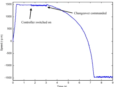
0 0.5 1 1.5 2 2.5 3 3.5 4 4.5 -1500 -1000 -500 0 500 1000 1500 Time (s) S p e e d (r. p .m) Changeover commanded
Controller switched on
Fig. 5 – Speed Control from 1000 r.p.m. to –1000 r.p.m.
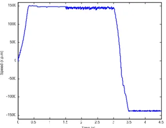
Fig. 5 shows simulation result of the induction motor with the newly designed fuzzy controller. Here the desired speed initially was 1000 r.p.m. After 0.6 s the motor shaft has been loaded. From beginning, the motor is running with normal synchronous frequency. At 1.6 s the fuzzy controller is switched on and it takes over the control mechanism. At 3 s a command is given to change the speed of the motor from 1000 r.p.m to –1000 r.p.m. Fig. 5 depicts how well the fuzzy controller changes over the speed even in the loaded condition. Fig. 6 depicts similar speed changeovers from 1500 r.p.m to –1500 r.p.m. Simulation has been carried out with 1 kHz sampling frequency.
0 1 2 3 4 5 6 7 8 9
-1500 -1000 -500 0 500 1000 1500 Time (s) S p e e d ( r. p .m ) Changeover commanded
Controller switched on
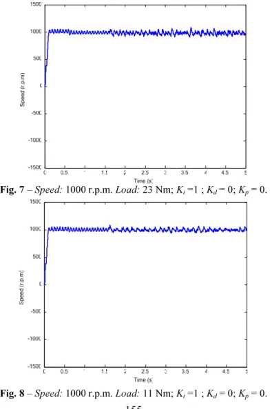
In order to eliminate continuous maintained speed error, an integrator has been introduced after speed error is calculated. Accordingly, torque error and flux error are calculated and fed to fuzzy controller. Performances deteriorate drastically if derivative component of speed error signal is fed to the controller to take care of transients. It has been observed, during change in direction of rotation, proportional error signal is suitable. Figs. 7 - 13 demonstrates such per-formances under varying load conditions and different commanded speeds. Here Kp, Ki and Kd are constants of proportional, integral and derivative (PID)
components, which in some cases have been considered 1 without optimizing or tuning the constants. The loading time and fuzzy controller coming in action remains same as mentioned in the previous cases.
Fig. 7 – Speed: 1000 r.p.m. Load: 23 Nm; Ki =1 ; Kd = 0; Kp = 0.
Fig. 9 – Speed: 1000 to –1000 r.p.m. Load: 23 Nm; Ki =0 ; Kd = 0; Kp = 1.
Fig. 10 – Speed: 1000 to –1000 r.p.m. Load: 11 Nm; Ki =0 ; Kd = 0; Kp = 1 with motor model speed estimator.
estimati-on of speed, which can further improve performance of the drive. The perfor-mance will further improve with increase in sampling frequency. But there are some limitations. It has been observed that the controller is suited up to speeds of ±700 r.p.m. Better design of the fuzzy controller with different membership functions and tuning of PID parameters will improve performance of the motor control even for lower speeds. However, presently the new control method has been discussed and further improvement has been kept for future work. The pre-sent work highlights capability of the new method for bi-directional control of induction motor with reduced rule base. Introduction of the final state selector helped to reduce the rule base to 36 rules as compared to 72 rules for direct tor-que control. Thus the advantage of the proposed technitor-que is to improve real ti-me processing. Moreover, it presents a new control technique of induction motor.
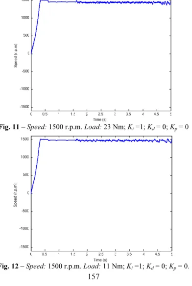
Fig. 11 – Speed: 1500 r.p.m. Load: 23 Nm; Ki =1; Kd = 0; Kp = 0
Fig. 13 – Speed: 1500 to –1500 r.p.m. Load: 11 Nm; Ki =0; Kd = 0; Kp = 1 with motor model speed estimator.
7 Conclusion
Though several methods of control of induction motor exist, here an intelligent controller has been developed. The new method of control of induction motor depicts good speed control under varying load conditions and transition from clockwise to counterclockwise direction or vice-versa. The reduced rule base with bi-directional control capability helped to improve processing time of the controller, which can be utilized for other control actions in real time processing environments.
8 References
[1] A.M. Trzynadlowski: Control of Induction Motors, Academic Press, 2001.
[2] Pradeep Chatterjee, Rajpal Singh, B.M. Karan, P.K.Sinha: Application Specific Fuzzy Switching, International Conference on Control, Instrumentation and Information Commun-cation, Kolkata, India, December 2001.
[3] James N. Nash: Direct Torque Control, Induction Motor Vector Control Without an Encoder, IEEE Transactions on Industry Applications, Vol. 33, No. 2, March/April 1997.
[4] Pradeep Chatterjee, Rajpal Singh, B.M. Karan, P.K. Sinha: Encoding Fuzzy Controller of Induction Motor, Industrial Engineering Journal, Vol XXXII, No. 6, June 2003, pp. 7-10. [5] B. K. Bose: Expert Systems, Fuzzy Logic, and Neural Network Applications in Power
Electronics and Motion Control, Proc. IEEE, Vol. 82, pp. 1303–1323, Aug. 1994.
[7] R. Ortega, N. Barabanov, G. Escobar: Direct Torque Control of Induction Motors: Stability Analysis and Performance Improvement, IEEE Trans. Automat. Contr., Vol. 46, pp. 1209– 1222, Aug. 2001.
[8] G. Buja, D. Casadei, G. Serra: Direct Stator Flux and Torque Control of an Induction Motor: Theoretical Analysis And Experimental Results, in Proc. IEEE-IECON, Aachen, Germany, 1998, pp. 50–64.
[9] J. C. Hung: Practical Industrial Control Techniques, in Proc. IEEE IECON’94, pp. 7–14. [10] Hongwen Wang, Gang Ge, Nan Tan, Han-Po Zhang, Li-Ping Yan': AC Induction Motor
Direct Torque Control System with Fuzzy Controller, Proceedings of the Second International Conference on Machine Learning and Cybernetics, Wan, 2-5 November 2003, pp. 800-802
[11] Chiraz Ben Jabeur-Seddik, Farhat Fnaiech: Hysteresis and Fuzzy Based Nonlinear Controllers for a Direct Torque Control of An Induction Machine, 2004 IEEE International Conference on Industrial Technology (ICITJ), pp. 38-43.
[12] Jia-Qiang Yang, Jin Huang: Direct Torque Control System for Induction Motors with Fuzzy Speed PI Regulator, Proceedings of the Fourth International Conference on Machine Learning and Cybernetics, Guangzhou, 18-21 August 2005. pp. 778-783.
[13] Lin Chen, Kang-Ling Fang, Zi-Fan Hu: A Scheme of Fuzzy Direct Torque Control for Induction Machine, Proceedings of the Fourth International Conference on Machine Learning and Cybernetics, Guangzhou, 18-21 August 2005. pp. 803-807.