! "#$% & & '
! "#$%
' & ! (
) !
! (
! '
$ ! "
*
$
+,-! ( ' .
'
$ */" !
0
1 */" & &
2 &
"#$% !
' !
Recent developments in power
electronics, fast digital signal processors (DSPs) and modern control technologies have significantly influenced the wide spread use of permanent magnet brushless (BLDC) motor[3] drives in order to meet the competitive worldwide market demands of manufactured goods, devices, products and processors. Large, medium, small as well as micro BLDC motors are extensively sought for applications in all sorts of motion control [7] apparatus and systems. The availability of smart power electronics devices and their optimal topologies has accelerated unprecedented growth of cost effective and reliable inverter and converter
systems. Software controlled online
implementation of sophisticated robust controllers has advanced the art of digital control of BLDC motor drives. In electric traction, like in other applications, a wide range in speed and torque control for the electric motor is desired. The DC machine fulfills these requirements but these machines needs periodic maintenance. The AC machines like induction motors and brushless DC motor [1] does not have brushes, and their rotors are robust because commutator and or rings do not exist. That means very low maintenance. This also increases the power to weight ratio and efficiency. For induction motors flux control has been developed, which offers a high dynamic performance for electric traction application however this control type is complex and sophisticated. The development of BLDC has permitted an important simplification in the hardware for electric traction control. The term
“Brushless DC motor”[1] is used to identify the combination of AC machine, solid state inverter and rotor position sensor that results in a drive system having a linear torque – speed characteristic as in an conventional DC machine High efficiency due to reduced losses, low maintenance and low rotor inertia of the BLDC motor have increased the demand of BLDC motors in high power servo [4] and robotic applications. The invention of modern solid state devices like MOSFET, IGBT and high energy have widely enhanced the applications of BLDC motors in variable speed drives. In this work, a digital controller is developed for this drive which uses minimum number of components employing a recently introduced DSP (TMS320F240) by Texas Instruments (TI) for power electronics applications7. First the control scheme of the drive is analyzed and its simulated results are validated with test results obtained from developed digital controller
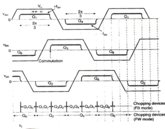
The drive consists of speed controller, reference current generator, PWM current controller, position sensor [2], the motor and IGBT. The speed of the motor is compared with its reference value and the speed error is processed in proportional - integral (PI) speed controller. The output of this controller is considered as the reference torque. The BLDC motor is characterized by a two phase ON operation to control the inverter. In this control scheme, torque production follows the principle that current should flow in only two of the three phases at a time and that there should be no torque production in the region of Back EMF zero crossings. The following figure describes the electrical waveforms in the BLDC motor in the two phases ON operation.
Commutation provides the creation of a rotation field. As explained, it is necessary to keep the angle between stator and rotor flux close to 90° for a BLDC motor to operate properly. Six-step control creates a total of six possible stator flux vectors. The stator flux vector must be changed at a certain rotor position. Hall sensors usually sense the rotor position. The Hall sensors generate three signals that also comprise six states. Indeed the drive characteristic and control methods are very similar for the trapezoidal and sinusoidal machines and in both cases the motor must be energized with controlled currents that are synchronized with rotor position.
!
" #
$
G.MadhusudhanaRao1, B.V.SankerRam2, B.Smapath Kumar3, K.Vijay Kumar4
1
JNTUH Hyderabad, India 2
Figure 1: Stator phase voltages and current waves indicating the converter conducting devices
However a distinction is now being drawn between the two drive because of the differences in machine construction and because the standard synchronous motor requires sinusoidal current excitation whereas the trapezoidal machine is energized, with square-wave and quasi square wave currents. The rotor position sensor [2] for the trapezoidal machine usually consist of a number of simple position detectors such as hall, effect devices that can sense rotor magnetic [5] field and so determine the phase switching points. The sinusoidal machine requires more precise position information to allow accurate synthesis of the sinusoidal current waveforms.
Figure 2: Proposed control mechanism for BDCM.
In this paper presented a simple and efficient modulation control system, which allows having good current waveform. To fulfill these objectives, a BDCM is used because of following advantages:
1. The position sensor system for the shaft needs only to deliver six digital signals for commanding the transistor of the inverter. 2. The quasi square wave armatures current
are mainly characterized through their maximum amplitude value, which directly controls the machine torque.
3. The inverter performance is very much reliable because there are natural dead times for each transistor.
% $
%
I) First Design Condition
The PWM based on the triangular carrier method has to set a commutation frequency lower than (or equal to) the carrier. This condition can be expressed as
2Af ≥
2
Af
K
|
m
|
dt
)
t
(
dPI
2 p
2
⇒
≥
α
---(1)
In other words, the slope of the PI control must not exceed the slope of the carrier. The (1) gives a design condition related with the carrier
amplitude and frequency (f), and the
proportional gain . On the other hand, an expression related with the integral gain is not obtained in a straight way.
II) Second Design Condition
To get , it has been proposed, as a starting point, to consider the integral gain as the product of the proportional gain with the carrier frequency. However, it is possible to get an approximate expression and the graphics as shown in Fig 1:
KI = 2
ref 1 I
t 0 c
)
I
(
|
m
|
M
2
K
dt
)
t
(
e
M
α
≤
⇒
∫
--- (2)(Approximate expression)
2
t
)
I
(
dt
e
dt
e
t ref 00 c t
0 c
0
α
≈
≥
∫
∫
|
m
|
2
)
I
(
dt
e
1 2 ref t
0 c
0
α
≥
∫
To close the control loop, it is required to estimate the integral error under steady-state conditions. One way to do that is to assume that the value of the integral is higher than the one given by the integration of the error at the initial interval. This is better explained with the help of Fig1. Then, using expression and the assumption given by Fig 1& the calibration of the PI control can be initiated.
The drive system considered here consists of PI speed controller, the reference current generator, PWM current controller, BLDC motor and an IGBT inverter. All these components are modeled and integrated for simulation [6] in real time conditions.
$ $
rotor speed ω( is compared with the reference
speed ω( and the resulting error is estimated at
the th sampling instant.
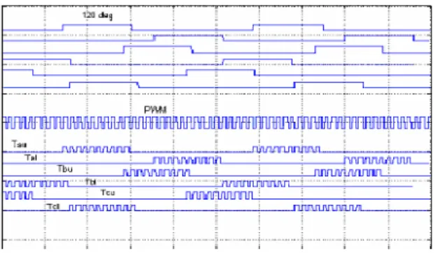
Figure 3: Digital operation of the position sensor: (a) position sensor signals, (b) PWM signal, and (c) gating
signals for the IGBTs
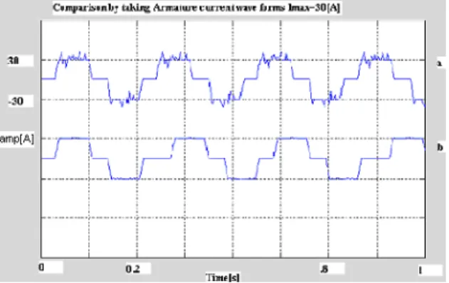
Figire 4: Generation of IMAX through the phase
currents: (a) phase-a current, (b) rectified current signal using only one phase, with 120
missing information, (c) phase-b current.
Figure 5: Inverter Circuit with BLDC Machine
' $' ( " )"
IGBT is selected as power switch for the inverter instead of MOSFET because the former is more suitable for low voltage and high speed switching application. As the rating of BLDC used in laboratory is 12V, 30A, IRF1607 IGBT is used. The two operations are realized through the three-phase inverter depicted in the following scheme.
* +ππππ,- # ." ' /
The operation of Inverter in this mode is explained with the help of the waveforms shown in Fig 5. The size switches of the inverter (Q4 – Q6)
operate in such a way place the input DC current Id,
symmetrically for the 2π/3 angle at the center of
each phase voltage wave. The angle α shown is the
advance angle of current wave with respect to voltage wave. In this case, α is zero, It seems to be
at any instant, two switches are ON, one in the upper group and another in the lower group. For example for instant t1, Q1 and Q6 are ON when the
supply voltage Vd and line current Id are placed
across line ab (phase a and phase b in series). So that Id is positive in phase a, but negative in phase
b. Then, after π/3 interval (the middle of phase a),
Q6 is turned OFF and Q2 is turned ON, but Q4
continues conduction for the full 2π/3 angle. This
switching commutates -Id it from phase b to phase c
while phase a continues to carry +Id as shown. The
condition pattern changes at every π/3 angle,
indicates six switching modes in a full cycle. The absolute position senor indicates the switching or commutation of the device at the precise instant of the waves. It can easily be seen from Fig 5, that at any instant two phases (2Vc) appear in series across
the inverter input. The power flow to the machine at any instant is ideally constant and is given by P=2Vc Id.asshown in fig1. The inverter is basically
operated as a rotor position sensitive electronic commutator (similar to a mechanical commutator in a DC machine).
* $0 # )
As we seen the inverter switches were controlled to give commutator function only when the device are sequentially ON for 2π/3 angle
duration. In addition to the commutator function, it is possible to control the switches in PWM chopping mode (buck converter) to control voltage and current continuously at the machine terminal. Fig1 showed the wave forms with chopping mode current controlled operation of the inverter. There are essentially two chopping modes feed back mode (FB) and free wheeling (FW) mode. In these modes, the devices are turned ON and OFF on a duty cycle basis to control the machine average IAV
and the corresponding voltage VAV, for example, In
the FB mode for the π/3 interval from instant t1
When Q1 and Q6 are chopping together, Q1, Q6 are
ON phase ‘a’ and phase ‘b’ currents will increase (Vd>2 Vc). However, when the devices are turned
OFF, the current will decrease because of feed back through diodes D3, D4 and the average machine
terminal voltage Vav will be determined by the duty
ratio.
The average phase voltage is given as Vav= Vc+ Iav Rs.
* / / " -+1 +21
an interrupt flag (INT6 of the DSP controller core) and the interrupt sub routine is executed. The ADC reading for 30 A will be 3FFh and 0 A will be 0h.
Timer 2 is selected as the time base for the capture unit. T2PER register is set to 0XFFEh. The rising and falling edges of the sensor output are detected, the corresponding interrupt flag is generated and the interrupt sub routine is served. In the speed loop code, every variable is stored into a stack. The stack pointer is used in the auxiliary register AR2. For hard chopping mode with CPU clock is 20MHz, PWM period of 5 KHz is selected. Integral time constant and controller gain values are chosen by trial and error method
For the purpose of electronic commutation of the Brushless motor, it is required to know the instantaneous angle of the rotor. This information is obtained from the Hall Effect sensor. The O/P is filtered and sampled by the ADC. From the sampled value we get the rotor position. The three Hall Effect sensors provide three overlapping signals giving a 60° wide position range. The three signals can be wired to the ‘F24x DSP’ Input Capture pins, thus speed information is available by measuring the time interval between two Input Captures.
' ) " )"
The Modulator Control Circuit has sub blocks of analog and digital electronic circuits (Comparators, PI controller, and Adder devices). The Main current is compared with a desired reference IREF and from this comparison, an error
signal ‘e(t)’ is obtained. This error signal e(t) is then processed to a PI control. The output of the PI control is compared with a triangular waveform of fixed amplitude and frequency, which gives a common and unique pulse width modulation for the three phases of the motor. This unique PWM pattern and the information given by the position sensor [2], generates the modulation signals for each transistor. The PWM controls the magnitude Main current and the position sensor discriminates when the PWM has to be applied to each of the six transistors, creating the correct sequence for the rotation of the machine.
Figure. 6: Modulation details with IREF = 50 [A]:
currents per phases and control signals for a 2000 [rpm] operation.
Figure 7: Armature current waveforms,
(a)Conventional method with periodical sampling and quasi-square template and (b) proposed method
with triangular carrier
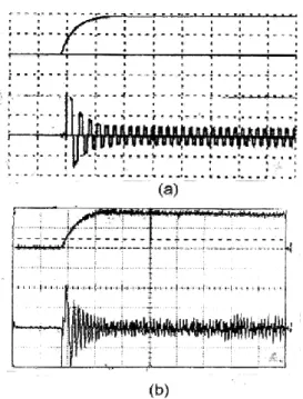
Figure 8(a) Simulation results of the drive system during starting [speed scale 250 rpm/div, current scale
2.54A/div, time scale 500 ms/div] (b) Experimental results of the drive system during starting [speed scale 250 rpm/div, current scale 2.54
A/div, time scale 500 ms/div]
$ 3
Fig8 (a) shows the simulated results and Fig8 (b) the experimental results of the rotor speed and winding current of the PMBLDCM drive for the starting of the motor from standstill to a speed of 47rad/sec (450 rpm). It is observed that the drive takes 650m.sec to reach the set speed. The PI speed controller comes into action and tracks the reference speed. From these figures it is clear that the speed response has no overshoots and oscillations and confirms the proper design of PI controller. The close agreement between simulated and test results can be observed from Fig (7) and Fig (8). Since maximum winding current is limited to same value in the tests and simulations, the starting time is also observed to be the same. A high frequency noise is noticed only in test results, which is obviously not present in simulated results due to various assumptions considered in the modeling.
[1] N. Hemati and M. C. Leu, “A complete model characterization of brushless dc motors,”
, vol. 28, pp. 172–180, Jan./Feb. 1992.
[2]. Juan W. Dixon, Matías Rodríguez and Rodrigo Huerta., Simplified Sensor less Control for BLDC Motor, Using DSP Technology
[3] A. R. Millner, “Multi-hundred horsepower permanent magnet brushless disc motors,” in
, Feb. 13–17, 1994, pp. 351–355. [4] P. Pillay and R. Krishnan, “Application characteristics of permanent magnet synchronous and brushless dc motors for
servo drives,” , vol. 27, pp. 986–996,
Sept./Oct. 1991.
[5] T. Lowand M. A. Jabbar, “Permanent-magnet motors for
brushless operation,” , vol. 26, pp.
124–129, Jan./Feb. 1990.
[6] P Pillay and R Krishnan. ‘Modeling, Simulation and Analysis of a Permanent Magnet Brushless dc Motor Drive.’
! ", 1987, p 8.
[7] Yasuhiko Dote. ‘Servo Motor and Motion Control using Digital Signal Proc-essors.’ # , Eagle Wood, Cliffs, New Jersey, 1990.
[8] ‘User’s Guide (vol.1 and.2) of TMS320F240 DSP’ of Texas Instruments, 1998.
3 4 $3%
5 ') ) ' , Research scholar in JNT University
and completed M.Tech from JNT University-Hyderabad in 2005 .He has Published 4 research papers in International Journals and 3 International conference papers and 8 national conference papers.
+
7 /, Professor in JNT University-Hyderabad in the Department of Electrical Engineering and completed his M.Tech from Osmania University in 1984, and his Ph.D from JNTU-Hyderabad. He has published more than 10 research papers in International journals in various fields of Electrical Engineering and also more number of national and international conference papers.
6 " :[email protected]
- / '8)/ , Assistant Professor and completed M.Tech
from JNT University-Hyderabad in 2005 .He has published many research papers in International Journals and International conference papers and national conference papers.
6 " : [email protected]
28 "9 : 8)/ , Associate Professor in Vignan University