Genetic Fuzzy Logic Control Technique for a Mobile Robot
Tracking a Moving Target
Karim Benbouabdallah and Zhu Qi-dan
College of Automation, Harbin Engineering University Harbin, 150001, China
Abstract
Target tracking is a crucial function for an autonomous mobile robot navigating in unknown environments. This paper presents a mobile robot target tracking approach based on artificial intelligence techniques. The proposed controller calculates both the mobile robot linear and angular velocities from the distance and angle that separate it to the moving target. The controller was designed using fuzzy logics theory and then, a genetic algorithm was applied to optimize the scaling factors of the fuzzy logic controller for better accuracy and smoothness of the robot trajectory. Simulation results illustrate that the proposed controller leads to good performances in terms of computational time and tracking errors convergence.
Keywords: Mobile robot, Target tracking, Fuzzy logic controller, Genetic algorithm.
1. Introduction
An autonomous mobile robot is a programmable and multi-tasks mechanical device, capable to navigate freely or execute different functions such as obstacles avoidance,
target tracking …etc.
The last few decades have witnessed ambitious research efforts in the areas of mobile robotics, due to their wide range of use in different fields like military and industrial applications. These research works aim to improve their operational capabilities of navigation and interaction with its surrounding work environments through the different kinds of sensors.
Target tracking is one of the basic and an interesting function for a mobile robot, and researchers have worked to propose different control approaches to improve target tracking performances. Several control approaches like PID controllers [1], non linear controllers based Lyapunov stability analysis [2] and sliding mode control [3] have been developed to make the mobile robot track easily a moving target. However, these approaches have showed some problems, due to the complexity of the mobile robot surrounding environment to be modeled or to the simplification assumptions taken for the elaboration of the mathematical model of the robot and control law.
To overcome these drawbacks and the need to exhibit robust performances while operating in highly uncertain and dynamic environments, artificial intelligence approaches have been attracting considerable research interest in recent years. Different techniques such as reinforcement learning [4], neural networks [5], fuzzy logics [6] [7] and genetic algorithms [8] have been applied to synthesize control laws enabling the mobile robot to follow a moving target freely. Artificial potential field approaches [9] [10] have been also developed to solve the problem of mobile robots target tracking.
The intelligent control does not require knowing exactly the mathematical model of the mobile robot or its surrounding work space, since it uses human reasoning and decision making in spite of uncertainty and imprecise information provided by the different perception sensors such as cameras, ultrasonic and infrared sensors.
Hence, the use of genetic algorithms is more suitable for this kind of situations.
In this paper, a control approach for target tracking by a mobile robot is presented, based on fuzzy logics and optimized with a genetic algorithm for more efficiency and effectiveness. The paper is organized as follows. A general description of the system model and problem formulation are given in section 2. The adopted fuzzy logic controller is presented in section 3. Section 4 describes the genetic algorithm used to tune the FLC. To validate the proposed approach, simulation results are discussed in section 5. Conclusion and future works are given in section 6.
2. Model System and Problem Formulation
The objective of this paper is to make an autonomous mobile robot track a moving target. To realize that, we shall assume that:
- The target and the robot move on the same plane in the absence of obstacles.
- The target moves along an unknown trajectory and its position is denoted as
o x
T(
T,
y
T)
.- The robot has the kinematics of a unicycle. It is described by the following equations:
.
.
.
cos
sin
x
V
y
V
w
(1)
where
( , )
x y
are the robot coordinates in the world frame XOY, is its orientation with respect to the same frame, andV
andw
are the robot linear and angular velocities. - The robot is subject to non-holonomic constraint:. .
cos sin 0
y
x
(2)The linear and angular positions of the mobile robot to the target to be tracked are denoted as
D
and
, respectively and can be written by the following equations:1
2 2
tan ( )
( ) ( )
T
T
T T
y y
x x
D x x y y
(3)
Roughly speaking, to achieve the target tracking objectives, the main idea is to design an intelligent controller enabling the robot to move freely such that it maintains a desired distance to the target and steer in order
to point the target’s direction.
Fig. 1 Schematic model of a mobile robot tracking a target.
3. Design of the Fuzzy Logic Controller
The fundamental objective is to synthesize a robust control law able to force the mobile robot to follow a moving target as closely as possible.
We define the distance and angle errors and the change in angle error variables to mathematically formulate the control objective as follows:
( )
(
1)
D d
d
e
D
D
e
e
e k
e k
(4)
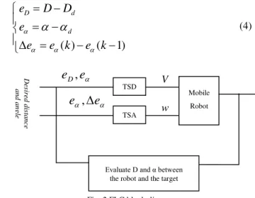
Fig. 2 FLC block diagram
De
sir
ed
dis
tance
and
angle
e
e
,
w
Mobile Robot V
TSD
TSA
e
e
D,
It’s clear that to achieve the control objective, it suffices to
make the tracking errors tend to zero. Thus, two fuzzy logic Takagi-Sugeno controllers of order zeros have been designed: distance controller TSD and angle controller TSA.
3.1 Distance controller TSD
This controller aims to keep a desired distance d
D
between the mobile robot and the target when it navigates in its work space. The control input variables are chosen as the distance and angle errorse
Dande
. The linear velocity of the mobile robotV
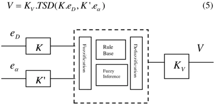
is defined as the output of TSD, so we can write:. ( . , '. )
V D
VK TSD K e K e (5)
Fig. 3 Distance controller architecture
The inputs/output linguistic variables are defined as:
:{ ,
,
,
,
}
:{
,
,
,
,
,
,
}
:{ ,
,
,
,
}
D
e
N ZE PS PM PB
e
NB NM NS ZE PS PM PB
V
N ZE PS PM PB
Triangular distributions in [-1, 1] interval were chosen as membership functions for the scaled inputs
e
Dande
and singletons forV
.Table 1 shows the rules’ base of TSD. For example, if the
errors are big, it means that the robot is so far from the target, so it should be much faster to reduce the distance to
D
d.Table 1: TSD Rules’ Base
Linear Velocity
Distance Error N ZE PS PM PB
An
g
le Err
o
r
NB N PS PM PB PB NM N ZE PS PM PB NS N ZE PS PM PB ZE N ZE PS PM PB PS N ZE PS PM PB PM N ZE PS PM PB PB N PS PM PB PB
3.2 Angle controller TSA
This controller aims to point the mobile robot in the
moving target’s direction, which means reduce the angle
error to zero. It has two input variables; the angle error
e
and the change of error
e
. It returns the angular velocity of the mobile robotw
, so we can write:. ( '. , ''. ) w
wK TSD K e K e (6)
Fig. 4 Angle controller architecture
The inputs/output linguistic variables are defined as:
:{
,
,
,
,
,
,
}
:{
,
,
,
,
,
,
}
:{
,
,
,
,
,
,
}
e
NB NM NS ZE PS PM PB
e
NB NM NS ZE PS PM PB
w
NB NM NS ZE PS PM PB
Table 2: TSA Rules’ Base
Angular Velocity
Angle Error
NB NM NS ZE PS PM PB
Ch
a
n
g
e
In
Err
o
r
PB ZE NS NB NB NB NB NB PM PS ZE NS NM NM NB NB PS PB PS ZE NS NS NM NM ZE PB PM PS ZE NS NM NB NS PB PM PS PS ZE NS NB NM PB PB PM PM PS ZE NS NB PB PB PB PB PB PS ZE
Triangular distributions in [-1, 1] interval were chosen as membership functions for the scaled inputs
e
and
e
and singletons forw
. The rules’ base of the controller TSA is depicted in Table 2.Note that the inputs’ scaling factors of the two fuzzy logic
controllers
( ,
K K K
',
'')
will be optimized with the genetic algorithm. The outputs’ scaling factors(
K
V,
K
w)
are not optimized because they do not affect the controllers’performances. This appears to be due to the scaling down of the linear velocity to not exceed the maximal velocity of the mobile robot.
e
D
e
V
Fuzzy Inference Rule Base
De
fuz
zif
ica
ti
on
F
uz
zif
ica
ti
o
n
K
VK
'
K
e
e
w
Fuzzy Inference
Rule Base
De
fuz
zif
ica
ti
on
F
uz
zif
ica
ti
on
w
K
'
K
4. The adopted Genetic Algorithm
In this part, a genetic algorithm is applied to tune the FLCs inputs scaling factors in order to guarantee a fast and smooth robot trajectory by reducing computational time and control errors.
A fitness function is used as a convergence criterion to
satisfy to measure the best values of the FLCs inputs’
scaling factors. The fitness function
J
is chosen as:2 2
1
(( ) ( ) ) 2 (1) (1)
D
D
e e
J dt
e e
(7)where
e
D(1)
ande
(1)
are the tracking errors at the initial positions of the robot and the target.Once the genetic representation of the population and the fitness function are defined, the genetic algorithm proceeds to initialize a population of solutions, which is usually generated randomly and then try to improve it through repetitive application of operators of selection, mutation and crossover.
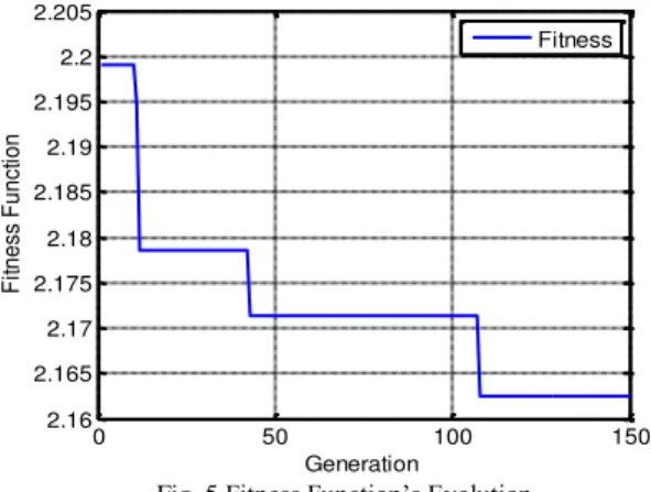
Fig. 5 shows the fitness function evolution according to the number of generation of the genetic algorithm.
The steps involved in the proposed genetic algorithm are summarized with the following steps:
Step 1: Generate an initial random population of individuals for a fixed size according to the variation range of each scaling factor.
Step 2: Evaluate the fitness of each individual in the population.
Step 3: Select fittest individuals of the population for reproduction.
Step 4: Breed new individuals through reproduction, crossover and mutation operators.
Step 5: Repeat step 2 until the convergence criterion is achieved.
Once the genetic algorithm is completed, it will return
three parameters corresponding to the inputs’ scaling
factors of the two designed fuzzy logic controllers TSD and TSA; which are the best population found during the execution of GA.
0 50 100 150
2.16 2.165 2.17 2.175 2.18 2.185 2.19 2.195 2.2 2.205
Generation
F
itn
e
ss
F
u
n
ct
io
n
Fitness
Fig. 5 Fitness Function’s Evolution
The population’s size and generations’ number are the
most significant parameters of GA since they have direct influence on the convergence of the GA to the optimal solution. Table 3 and 4 show the genetic algorithm results
for different size of population and generations’ number.
Table 3: GA’s Results with Population Size S=30
Generations
K
K
'
K
''
J50 3.8844 0.6251 0.3247 2.1605
100 3.7341 0.6287 0.3389 2.1615
150 3.9797 0.6208 0.3219 2.1625
Table 4: GA’s Results with Generations G=50
Population
size
K
K
'
K
''
J10 3.7493 0.6212 0.4950 2.1851
30 3.8844 0.6251 0.3247 2.1605
50 3.4694 0.6333 0.4043 2.1702
5. The Simulation Results and Discussions
To perceive the effectiveness of the control scheme proposed in this paper, we have simulated both the fuzzy logic controller and its optimization with the genetic algorithm using Matlab 7.0 ; when the mobile robot pursue a target moving along a circular path during the interval time [0, 55s], then a straight line path for the interval [55s,
90s]. The target’s trajectory can be described by the
2 2
( 2.5) ( 2.5) 9 0.5 1
T T
T T
x y
y x
(8)
The initial positions of the mobile robot and target are given by (-1, 1) and (5.5, 2.5) respectively. The linear velocity of the target is set to be 0.2 m/s. The desired values of the distance and angle from the robot to the target are set to be
D
d
0.2
m
and
d
0
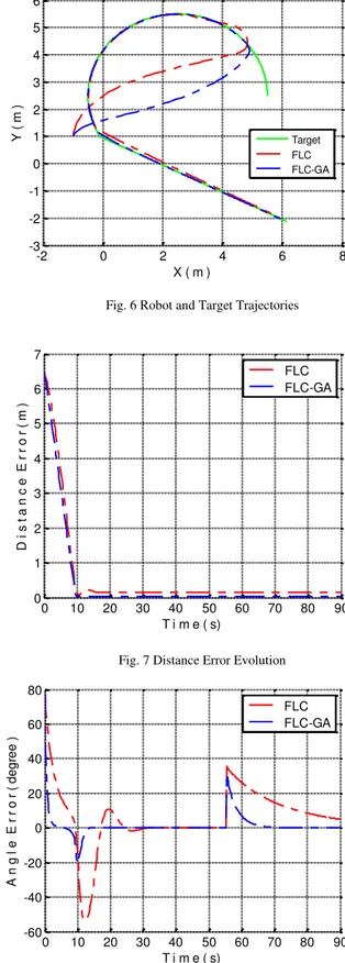
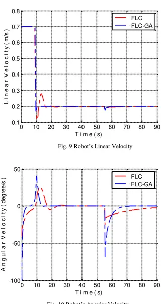
.The simulation results are depicted in Fig. 6 to Fig. 10. The trajectories of the target and the robot applying the two designed control laws are plotted in Fig. 6. Fig. 7 and Fig. 8 show the variation of the tracking errors during the motion of the target and the robot. Fig. 9 and Fig. 10 show
the evolution of the mobile robot’s linear and angular
velocities.
Table 4 presents the time of convergence of the tracking errors for both FLC and FLC-GA controllers.
Table 5: Time of Convergence of the Two Controllers
Convergence time (s)
Distance Error
Angle Error
FLC 15.6 32.5
FLC-GA 10 15
From Fig. 6, it can be observed that the robot track easily the moving target and catches up with it as well the tracking errors tend to zero.
In term of robot’s velocities, the robot moves forward with high speeds and evolve to stabilize then around the target’s
velocities as the tracking errors are converging to maintain
the control’s objectives (Fig. 7 to Fig. 10).
In the other hand, in term of comparison between the two
controllers’ performances, it’s obvious that the FLC-GA controller is much better than the FLC controller. In fact, the trajectory of the mobile robot under FLC-GA is much smoother and shorter than that under FLC, which presents deviations in its trajectory before it matches with that of
the target. The FLC’s outputs exhibit fluctuations at
various time instants with high magnitudes than those of the FLC-GA. As shown in Table 5, the FLC-GA is much effective than FLC in term of the speed of convergence of the tracking errors.
-2 0 2 4 6 8
-3 -2 -1 0 1 2 3 4 5 6
X ( m )
Y
(
m
)
Target FLC FLC-GA
Fig. 6 Robot and Target Trajectories
0 10 20 30 40 50 60 70 80 90 0
1 2 3 4 5 6 7
T i m e ( s)
D
i
s
t
a
n
c
e
E
r
r
o
r
(
m
)
FLC FLC-GA
Fig. 7 Distance Error Evolution
0 10 20 30 40 50 60 70 80 90 -60
-40 -20 0 20 40 60 80
T i m e ( s)
A
n
g
l
e
E
r
r
o
r
(
d
e
g
re
e
)
FLC FLC-GA
0 10 20 30 40 50 60 70 80 90 0.1
0.2 0.3 0.4 0.5 0.6 0.7 0.8
T i m e ( s)
L
i
n
e
a
r
V
e
l
o
c
i
t
y
(
m
/s
)
FLC FLC-GA
Fig. 9 Robot’s Linear Velocity
0 10 20 30 40 50 60 70 80 90 -100
-50 0 50
T i m e ( s)
A
n
g
u
l
a
r
V
e
l
o
c
i
t
y
(
d
e
g
re
e
/s
) FLC
FLC-GA
Fig. 10 Robot’s Angular Velocity
We have also tested the target tracking under different
outputs’ scaling factors
(
K
V,
K
w)
. The target and robot trajectories are depicted in Fig.11.Table 5: Outputs’ scaling factors
(
K
V,
K
w)
Case 1 Case 2 Case 3 Case 4 (1.3, 3) (2, 3.5) (2.5, 4) (3, 4.5)The trajectory of the robot under the different cases are almost the same and catches up the target at the same point within the convergence time; which can be explained by the saturation block added in the output of the TSD controller to scale down the linear velocity when it exceeds 0.7 m/s. Thus, the optimization of these factors is not
necessary since they don’t affect the controllers’
performances.
-2 0 2 4 6
-2 -1 0 1 2 3 4 5 6
X ( m )
Y
(
m
)
Target Case 1 Case 2 Case 3 Case 4
Fig. 11 Robot and Target Trajectories under different
outputs’ scaling factors.
6. Conclusions
This paper addresses the problem of the tracking of moving target along an unknown trajectory by a mobile robot. The proposed approach aims to design an intelligent controller based on fuzzy logic techniques and improved by a genetic algorithm.
The principal role of artificial intelligence techniques is their ability to design robust controllers with good performances in spite of the lack of information about the mobile robot or its surrounding environment models. Two fuzzy logic controllers based on Takagi-Sugeno model and
have been adopted to determine the mobile robot’s
velocities to fulfill the control objectives. A genetic algorithm has been also implemented to improve the FLC by optimizing its inputs scaling factors for better efficiency and effectiveness.
The provided simulation results show that the proposed approach acts successfully and enable the robot to track the moving target easily with good performances in term of convergence time and accuracy. The use of a genetic
algorithm to tune the inputs’ scaling parameters of the FLC makes the robot’s trajectory and the controllers’ outputs
much smoother and reduces considerably the convergence time and the tracking errors.
References
[1] P. K. Padhy, T. Sasaki, S. Nakamura and H. Hashimoto, "Modeling and Position Control of Mobile Robot", in International Workshop on Advanced Motion Control, 2010, pp. 100-105.
[2] R. Carelli, C. M. Soria, and B. Morales, "Vision-Based Tracking Control for Mobile Robots", in IEEE International Conference on Advanced Robotics, 2005, pp. 148-152. [3] J. Qiuling, X. Xiaojun, and L. Guangwen, "Formation Path
Tracking Controller of Multiple Robot System by High Order Sliding Mode", in IEEE International Conference on Automation and Logistics, 2007, pp. 923-927.
[4] R. Calvo and M. Figueiredo, "Reinforcement Learning for Hierarchical and Modular Network in Autonomous Robot Navigation", in International Joint Conference on Neural Networks, 2003, pp. 1340-1345.
[5] X. Ma, W. Liu, Y. Li and R. Song, "LVQ Neural Network Based Target Differentiation Method for Mobile Robot ", in IEEE International Conference on Advanced Robotics, 2005, pp. 680-685.
[6] T-H. S. Li, S. J. Chang, and W. Tong, “Fuzzy Target Tracking Control of Autonomous Mobile Robots by using Infrared Sensors ", IEEE Transactions on Fuzzy Systems, Vol. 12, No. 4, 2004, pp. 491-501.
[7] L. Ming, G. Zailin and y. Shuzi, "Mobile Robot Fuzzy Control Optimization using Genetic Algorithm", Artificial Intelligence in Engineering, Vol. 10, No. 4, 1996, pp. 293-298.
[8] L. Moreno, J. M. Armingol, S. Garrido, A. De La Escalera and M. A. Salishs, "Genetic Algorithm for Mobile Robot Localization using Ultrasonic Sensors ", Journal of Intelligent and Robotic System, Vol. 34(2), 2002, pp. 135-154.
[9] M. Taher, H. E. Ibrahim, S. Mahmoud and E. Mostafa, "Tracking of Moving Target by Improved Potential Field Controller in Cluttered Environments ", International Journal of Computer Science Issues, Vol. 9(2), No. 3,2012, pp. 472-480.
[10] L. Huang, "Velocity Planning for a Mobile Robot to Track a Moving Target - a Potential Field Approach", Robotics and Autonomous Systems, Vol. 57(1), No. 3,2009, pp. 55-63. [11] Q. Liu, Y-G. Lu and C-X. Xie, "Fuzzy Obstacle-avoiding
Controller of Autonomous Mobile Robot Optimized by Genetic Algorithm under Multi-obstacles Environment", in World Congress on Intelligent Control and Automation, 2006, pp. 3255-3259.
[12] C. Rekik, M. Jallouli, and N. Derbel, "Optimal Trajectory of a Mobile Robot by a Genetic Design Fuzzy Logic Controller", in International Conference on Advances in Computational Tools for Engineering Applications, 2009, pp. 107-111. [13] J. H. Holland, Adaptation in Natural and Artificial Systems,
Ann Arbor: University of Michigan Press, 1975.
[14] D. E. Goldberg, Genetic Algorithms in Search, Optimization and Machine Learning, New York: Addison-Wesley Professional, 1989.
Karim Benbouabdallah received his first university cycle diploma from National Preparatory School for Engineering studies, Rouiba, Algeria in 2005 and state engineering diploma in Systems Control from Military Polytechnic School, Bordj El Bahri, Algeria in 2008.
He then joined Harbin Engineering University, China as research staff working toward a Ph.D degree. His research interests include Vision in robotics, mobile robots navigation and intelligent control techniques.