Fuzzy control of induction motor with reduced rule base
Texto
Imagem


Documentos relacionados
Lin “Direct adaptive fuzzy-neural control with state observer and supervisory controller for unknown nonlinear dynamical systems” IEEE Transactions on Fuzzy
The class boundaries are given as spheres centered at (0. For Sphere, the inside of sphere is associated with class 1 and the outside with class 0. For Double-Sphere, the area
We also determined the critical strain rate (CSR), understood as the tangent of the inclination angle between the tangent to the crack development curve and the crack development
Speed Control of 3-Phase Induction Motor Using PIC18 Microcontrollers.. The frequency and speed of the motor, with respect to the input supply, is called the synchronous frequency
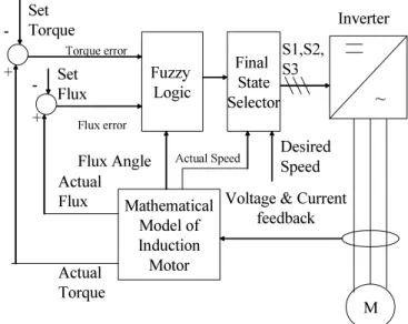
This switching strategy combines the advantages of matrix converter with the advantages of direct torque control technique, using a fuzzy speed controller and MRAS speed estimator..
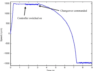
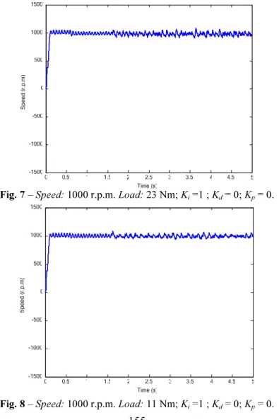
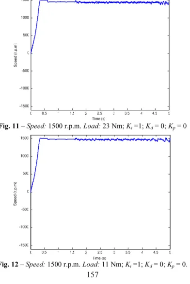
To perceive the effectiveness of the control scheme proposed in this paper, we have simulated both the fuzzy logic controller and its optimization with the
The optimum fuzzy logic control of an induction generator require controller which will track wind speed in order to achieve λ opt and thus extract
The current control loop consists of a hysteresis current controller (HCC). The block diagram of a hysteresis current controller is shown in Fig. HCC is used to
