ABSTRACT
Masaki MURAYAMA1, Yasuhiro NAMURA2, Takahiko TAMURA2, Hiroaki IWAI1, Noriyoshi SHIMIZU2
1- Department of Orthodontics, Nihon University School of Dentistry, Tokyo, Japan.
2- Division of Clinical Research, Dental Research Center and Department of Orthodontics, Nihon University School of Dentistry, Tokyo, Japan.
Yasuhiro Namura - 1-8-13 Kandasurugadai - Chiyoda-ku - Tokyo - 101-8310 - Japan - Phone: +81-3-3219-8105 - Fax. +81-3-3219-8312
!"#$"%&'$(&&($
T
!"# #$ " % ! &&'( &&') " * +,'-.)' &-% '&% (& /& "% 0 '& % 1 (& 1 from the proximal brackets exceeds 1.0 mm. The friction force of a martensite 0.014-inch ! 8 9 : more than 1.0 mm displacement.
Key words: Orthodontics. Friction. Esthetic. Materials.
INTRODUCTION
: plastic material, such as a synthetic fluorine-containing resin or an epoxy resin composed mainly < 18, has been used to satisfy esthetic demands. Several problems involving the 8>817 (2000) described the coat as “undurable”. Kusy13 (1997) found that % mastication forces and the activity of oral enzymes /in vivo. Elayyan, Silikas and Bearn5 (2008) reported that surface roughness
in vivo.
I , 11 (2012) reported that 8 %
mouth, exposing the underlying metal6. In addition, % % % as the durability of the coating material, may be
inferior to ,
<
1 and the
< 21.
* %&&'( !" %
7. In the initial stages
% : " depends on its size as compared to the bracket slot
room8%
less than the friction resistance, as interference, the dental arch must be expanded until the placement Thus, expansion of the dental arch in an extraction case can lead to poor-quality treatment, such as ! P " according to mechanical properties and fabrication. Although both have excellent springback properties, ! and superelasticity2,4,15. Thus, this issue should be 1 ! mechanical properties, and for plain and coated % and friction in small esthetic (including plated) linguoversion of the lateral incisor in the arch and an ISO bending test, and to compare esthetic and
MATERIAL AND METHODS
$ " ! P&&'( &&') " $'": /& < ! % according to ISO 1584110 U<% distance of 10 mm, a crosshead speed of 7.5 mm/ min, and a temperature of 36±1°C using a testing --XYZ + % !% #:% 0,:" ! elastic behavior during unloading at temperatures -&[9!1%< < /&%(&%'&%
&-during unloading.
Abb. Products Manufactures Surface treatment Wire sizes
A-1 Aesthetic nickel titanium wire TP Orthodontics Xylan-coated (only labial surface)
0.012” and 0.014”
A-2 Nickel titanium wire cosmetic arches coated
Forestadent coated
0.012” (coated 0.014”) 0.014” (coated 0.016”) A-3 Tynilloy wire lemon gold Dentsply-sankin Gold-plated 0.012” and 0.014” A-4 Tynilloy wire peach gold Dentsply-sankin Gold-plated 0.012” and 0.014” A-5 Tynilloy wire white Dentsply-sankin Fluorpolymer-coated 0.012” (coated 0.013”)
0.014” (coated 0.015”) P-1 TP Orthodontics N/A 0.012” and 0.014” P-2 Nitinol classic 3M Unitek N/A 0.012” and 0.014”
+ Wires used. The base wires A-1 to A-5 and P-1 were austenitic Ni-Ti, and P-2 was martensite Ni-Ti (Abb.: Abbreviation)
+ A dental arch-form plate model designed for the linguoversion of the lateral incisor in the arch
% * passive-ligating brackets (T-21; Tomy International, Tokyo, Japan; slot size, 0.022 inch; composition, bracket: polyethylene terephthalate etc, slot cap: "% $("&-%'&%(&% 3.0 mm displacement at the lateral incisor and the arch-form plate. The brackets and the end of the machine (5567; Instron; Figure 3). We applied tensile loading under a crosshead speed of 0.5 mm/ min and measured the maximum loading as the static friction force.
Descriptive statistics, including means and % unloading bending force and static friction force 'X&Z,>,,%
Chicago, IL, USA). Additionally, the Scheffé test {| comparisons among the products. A P value <0.05 8
RESULTS
U friction forces at displacements of 3, 2, 1.0, and &- ') At a displacement of 0.5 mm, unloading bending (Y..-X! 7.0-50.5 cN. At a displacement of 1.0 mm, unloading )(Y~'(/( ! ''(/X!0 (& -&/'X-) ! X'))) ! : displacement of 3.0 mm, unloading bending forces
0.012 inch 0.014 inch
?8=& (cN)
Friction force (cN) ?8=& (cN)
Friction force (cN)
Mean S.D. Mean S.D. Mean S.D. Mean S.D.
A-1 49.2 10.3 a, b, c, d
20.9 2 a 78.7 4.3 A 29.4 4.4 A
A-2 43 12.4 a, b, c, d
23 7.1 a 65.9 18.8 A, C 25.9 6.4 A
A-3 32.4 1.6 a 9.7 2.4 b 66.3 1.1 B, C, D 18.8 3.1 A, C
A-4 48.8 2.7 b 9.1 2.9 b 79.5 3 A 20.9 6.9 A, D
A-5 27.8 1.3 c 7 0.9 b 60.7 2.7 B, C, E 11.4 1.5 B, C, D
P-1 54.1 7.5 b, e 22.7 6.6 a 85.6 13.4 A, D, E 24.6 6.3 A
P-2 39.7 2.8 d, e 21.9 2.4 a 67.6 7.3 A, D, E 50.5 8.3 B Table 1- Unloading bending and friction forces at a displacement of 0.5 mm
!" # #$ %% & # '# % #* % % #; #$ %% &<==>; #? % #
0.012 inch 0.014 inch
?8=& (cN)
Friction force (cN) ?8=& (cN)
Friction force (cN)
Mean S.D. Mean S.D. Mean S.D. Mean S.D.
A-1 71.1 7.6 a, e, f 29.5 11.1 a, b 88.9 5.7 A 53.7 26.9 A, B, D
A-2 54.2 3.6 b, c 38.6 8.8 a 86.6 5 A, C 72.5 11.9 A, D
A-3 54.8 1.3 a, c 11.2 3.7 b, c 78.3 1.7 B, C 31.4 7.6 B, C
A-4 58.5 1.8 a, c 21.1 11 a, c, d 95.4 1.1 A, E 28 8.8 A, B
A-5 42.7 0.9 d 13.5 0.9 b, d 78.7 2.5 B, C 19.7 6.4 A, B
P-1 78.8 1.5 e 31.1 5.6 a 100.9 2 D, E 49.4 20.4 A, C
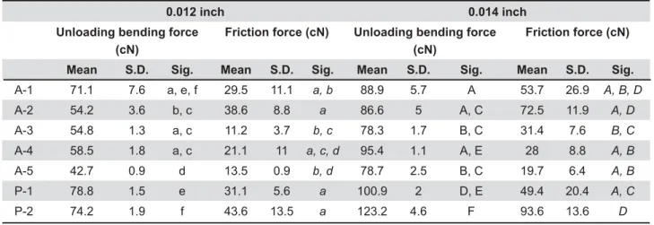
P-2 74.2 1.9 f 43.6 13.5 a 123.2 4.6 F 93.6 13.6 D Table 2- Unloading bending and friction forces at a displacement of 1.0 mm
0.012 inch 0.014 inch
?8=& (cN)
Friction force (cN) ?8=& (cN)
Friction force (cN)
Mean S.D. Mean S.D. Mean S.D. Mean S.D.
A-1 71.4 4.8 a, e, f 166 26.3 a, d 99 6.7 A, B, C 278.6 72.7 A, B
A-2 58.2 1.8 b, c 161.6 28.3 a, d 93.1 5.2 A 254.2 68 A, B
A-3 61.8 2 a, c 96.1 20.2 b, c 93.5 1.9 A 250.2 16.7 A, B
A-4 67.6 1.2 e 122.9 23.7 a, c 106.6 1.4 B 218.1 27.8 A, B
A-5 50.3 3.1 d 152.1 41.2 a, c, e 90.8 3.6 A 285 35.9 A
P-1 79.3 1.3 f 148.5 43.6 a, c, f 105 2.4 B 206 28.9 B
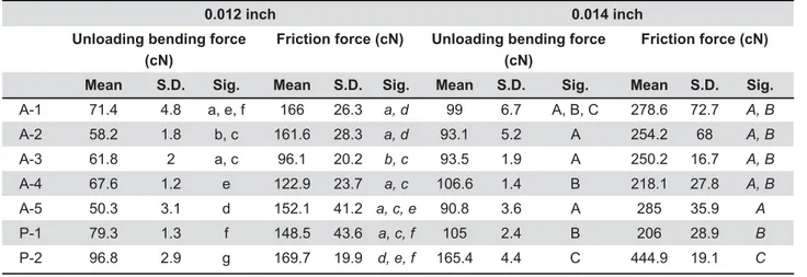
P-2 96.8 2.9 g 169.7 19.9 d, e, f 165.4 4.4 C 444.9 19.1 C Table 3- Unloading bending and friction forces at a displacement of 2.0 mm
!" # #$ %% & # '# % #* % % #; #$ %% &<==>; #? % #
0.012 inch 0.014 inch
?8=& (cN)
Friction force (cN) ?8=& (cN)
Friction force (cN)
Mean S.D. Mean S.D. Mean S.D. Mean S.D.
A-1 69.4 0.8 a 259.4 0.8 a, b 112.3 6.1 A 599.6 125 A
A-2 75.4 6.1 a, c 291.9 108.6 a, b 118.4 10.3 A 533.2 101.2 A
A-3 65.1 5.6 a, d 164.4 47.5 a 104.8 9.2 A 510.8 37.8 A
A-4 70.6 2 a 256.5 21 b, c 119.1 3.6 A 436 63 A
A-5 53.5 3.1 b, d 276 70.8 a, c, d 108.2 8.8 A 548.1 61.7 A
P-1 82.5 2.6 c, e 282.2 29.2 b, d 119.9 6.6 A 432.8 47.1 A
P-2 90 3.2 f 205.2 23.5 a 164.5 3.5 B 950.7 101.6 B Table 4- Unloading bending and friction forces at a displacement of 3.0 mm
!" # #$ %% & # '# % #* % % #; #$ %% &<==>; #? % #
+ Relationships between unloading bending and friction forces for 0.014-inch wires
-/-~'X)-! 'X)) 950.7 cN. Unloading bending and friction forces in %1&&') >(% 8
P $) -$&&'( &&') % all unloading bending forces at 0.5 and 1.0 mm |% 1 (& larger than the unloading bending forces.
DISCUSSION
At the leveling stage, tooth movement behavior and the friction resisting it. In this experiment, the friction force at displacements exceeding 2.0 mm
%1 the dental arch up to a displacement of 1.0 mm. Resistance to sliding has been reported to be slightly
14,23.
1 state, the relationship should not differ because most friction forces at displacements exceeding 2.0 forces.
Regarding the friction force, many studies have reported the use of experimental models to measure
3,19,22,24.
On the other hand, Henao and Kusy8 (2004) used N brackets, and reported friction forces of 250–675 cN
&&') !I%I U12
(2008) reported that the static friction force of a &&') ! .-(()& ! &/& displacement, identical to that used in this study. |% I% I U12 (2008) used a be displaced lingually. In our experiment, friction
&&') '')-&Y cN. Thus, if our dental arch model had bilateral % approximately doubled, although the ability to determine the actual friction force is limited in many cases by the simplicity of the model.
1 % self-ligating brackets to measure friction force. The % P 10.0 mm according to ISO 1584110, matches the interbracket distance in mandibular anterior teeth. Kim, Kim and Baek12 (2008) and Henao and Kusy8,9 (2004, 2005) reported friction forces obtained 1 : depends on the degree of tooth displacement and the brackets used, the force in the maxillary arch must be smaller than that in the mandibular arch because the interbracket distance in the mandible is |% 1 1 dental arch and friction resistance because the force
*
%,P20
(1932) reported that a safe force for tooth movement (&~(X2. Using a rat experiment model, Noda, et al.16 (2000) found that the optimal force )')+ this experiment, the smallest unloading bending (Y.! is translated as reciprocal action. Because the force that reaches the teeth becomes half of the unloading %&&'( displacement of 0.5 mm and those of some '& of doubtful use for optimal tooth movement.
< >' >(!>( ! " P " ! %>' that convey superelasticity, resulting in an almost even force during unloading2,4,15. Thorstenson and Kusy25 (2002) reported that the regression lines P ! ! In our study, at a displacement of 3.0 mm, the ratio &&') >( % 1 5.8-fold larger than the unloading bending force. % unimportant !$, P !%1 a larger ratio, is not likely to be superior to other % experiment.
CONCLUSIONS
* %Because the friction force at displacements exceeding 2.0 mm is larger than the force produced % expansion of the dental arch up to a displacement of 1.0 mm.
! 8 !The surface treatment of !
! !Z% ! are likely more appropriate for clinical use.
ACKNOWLEDGMENTS
% % from the Dental Research Center, Nihon University School of Dentistry.
REFERENCES
'U :#%, #>%> {%9!%9#$+ < of thermal or chemical degradation on the frictional force of an 1 !: (&''Z.').) 2- Bradley TG, Brantley WA, Culbertson BM. Differential scanning calorimetry (DSC) analyses of superelastic and non-superelastic :N 1996;109:589-97.
/U,$ :N (&&Z'/-))(Y ) U 9% U% # 9 ! orthodontic alloy. Am J Orthod. 1985;87:445-52.
5- Elayyan F, Silikas N, Bearn D. Ex vivo surface and mechanical 2008;30:661-7.
6- Elayyan F, Silikas N, Bearn D. Mechanical properties of coated brackets. Am J Orthod Dentofacial Orthop. 2010;137:213-7. 7- Harradine N. Self-ligating brackets; theory, practice and evidence. In: Graber TM, Vanarsdall RL, Vig KW Jr (ed.). Orthodontics: current principles techniques. 5th edition. St Louis:
Elsevier Mosby; 2011. p.581-614.
8- Henao SP, Kusy RP. Evaluation of the frictional resistance of conventional and self-ligating bracket designs using standardized : (&&)ZY)(&('' 9- Henao SP, Kusy RP. Frictional evaluations of dental typodont models using four self-ligating designs and a conventional design. Angle Orthod. 2005;75(1):75-85.
10- International Organization for Standardization. ISO 15841: N { +,Z(&&X '' I ::% , , : (&'(Z/)X&/ 12- Kim TK, Kim KD, Baek SH. Comparison of frictional forces during the initial leveling stage in various combinations of system. Am J Orthod Dentofacial Orthop. 2008;133:187.e15-24. '/I>: and characteristics. Angle Orthod. 1997;67:197-207.
14- Kusy RP, Whitley JQ. Resistance to sliding of orthodontic < % interbracket distance, and bracket engagement. J Biomed Mater Res. 2000;52:797-811.
15- Miura F, Mogi M, Ohura Y, Hamanaka H. The super-elastic ! Am J Orthod Dentofacial Orthop. 1986;90:1-10.
'X!I%%!%I optimal orthodontic force in various tooth movements: comparisons of tooth movement, root resorption, and degenerating tissue in tipping movement. Orthod Waves. 2000;59:329-41.
'Y>8*9 ,#Z(&&& 1 8 - Ra m a d a n A A . Re m o v i n g h e p a t i t i s C v i r u s f r o m < dental instruments. East Mediterr Health J. 2003;9:274-8. 19- Reznikov N, Har-Zion G, Barkana I, Abed Y, Redlich M. # :N Orthop. 2010;138:330-8.
(&,P:# movement. Int J Orthod. 1932;18:331-52.
21- Silva DL, Mattos CT, Sant' Anna EF, Ruellas AC, Elias CN. Cross-section dimensions and mechanical properties of esthetic :N 2013;143(4 Suppl):S85-91.
22- Stefanos S, Secchi AG, Coby G, Tanna N, Mante FK. Friction during sliding mechanics. Am J Orthod Dentofacial Orthop. 2010;138:463-7.
23- Thorstenson GA, Kusy RP. Resistance to sliding of self-ligating ": Orthod Dentofacial Orthop. 2001;120:361-70.
24- Thorstenson GA, Kusy RP. Comparison of resistance to angulation in the dry and saliva states. Am J Orthod Dentofacial Orthop. 2002;121:472-82.