*e-mail: [email protected]
In Situ
Observation of Phase Transformations in The Fe-Zn System
Maria Ismenia Sodero Toledo Fariaa*, Fernando Cosme Rizzo Assunçãoa, Sidnei Paciornika, Thomas Wroblewskib
a
Pontifícia Universidade Católica
Rua Marquês de São Vicente, 225, Rio de Janeiro - RJ, Brazil
b
HASYLAB at Desy, Hamburg
Received: February 7, 2003; Revised: August 17, 2003
In this study, the MAXIM technique was used in an attempt to clarify the phase transforma-tion sequence that occurs during in situ annealing of galvanized samples. A diffractometer equipped with a novel imaging system comprising a Micro-Channel Plate in front of a CCD camera was used. The galvanized samples were produced under typical industrial conditions, with effective aluminum content at 0.147wt.%. In situ experiments were performed and the phase evolution was recorded in real time. It can be concluded that, coupled to in situ thermal treatment, MAXIM is an efficient method to observe the evolution of the phases present in galvannealed samples. This technique has enough sensitivity to detect the evolution of the involved phases with good spatial resolution.
Keywords: galvanized steel, in situ annealing, MAXIM, Synchrotron Radiation
1. Introduction
Galvannealed steel is a material obtained through a hot-dip process that consists of the immersion of a steel sheet in a molten zinc bath containing small amounts of aluminum followed by an annealing heat treatment. Reactions between the iron of the substrate and the zinc in the bath occur dur-ing the immersion, givdur-ing rise to the galvanized material which corresponds to a steel coated with essentially pure zinc (η phase)1,2. The thickness of the coating and phases
present in it depend on the composition of the bath, substrate characteristics and operating conditions (strip temperature, time and velocity). The galvanized sheet becomes galvannealed through an additional annealing thermal treat-ment. The annealing process promotes the interdiffusion of iron and zinc, which may lead to the formation of brittle Fe-Zn intermetallic phases3,4.
The performance during mechanical processing is closely related to the amount and type of brittle Fe-Zn intermetallic phases present in the final coating5. The galvannealing
proc-ess must be precisely controlled in order to avoid excproc-essive coating detachment during press forming.
It has been found that a small addition of aluminum to
the liquid zinc bath delays the formation of Fe-Zn intermetallic compounds.This is believed to be due to the formation of a thin Fe-Al inhibiting layer between the zinc coating and the steel substrate6,7,8.
The understanding of the phase nucleation and growth mechanisms during the galvannealing process is essential to help improving the current process.
Despite the wide use of galvanized and galvannealed materials, many questions are still open regarding the evo-lution of phases in these systems.
The main goal of the present work is to explore the po-tential of a novel X-ray diffraction technique to follow phase transformations in situ. The MAXIM (MAterials X-rays IMaging), technique9,10, developed at the HASYLAB
2. Materials and Methods
2.1. Description of the material
The galvanized sample used in this work was produced by hot dipping under typical industrial galvannealing con-ditions. The substrate was rephosphorized IF steel (sample Ti-Nb-P-B IF) processed in a pilot line using an effective Al content of 0.147 wt.%. The substrate composition and processing condition for the selected material are summa-rized in Table 1 and Table 2, respectively.
2.2. Pre-characterization of the material
Preliminary tests were conducted to help design the in situ experiments. In these tests annealing was performed at 400, 450, or 500 °C for times varying from 1 to 360 min11. After
annealing, the samples were characterized using SEM, EDX and conventional X-ray diffraction. The main objective was to identify the time and temperature ranges that should be used to allow the formation of the intermetallic compounds. The coat-ing thickness and the presence of the intermetallic phases in the steel/coating interface were evaluated. The samples showed a behavior similar to that expected for samples that undergo a galvannealing treatment, even though all the reactions studied in this work occurred in the solid state. By studying the Fe-Zn reactions at 400 °C it was possible to follow the Fe-Zn phase evolution with a slower kinetics.
2.3. Experiments with the MAXIM Technique
The experiments were performed using a diffractometer mounted in the HASYLAB and the recently introduced MAXIM technique (MAterials X-rays IMaging) to follow the sequence of transformations that would take place dur-ing the in situ annealdur-ing of the samples galvanized as de-scribed above.
The diffractometer uses synchrotron light as an X-ray source with high collimation and a collimator array with
high spatial resolution. The diffracted X-rays are collimated by a Micro Channel Plate (MCP), a 2D matrix of collimator tubes. Thus, it is possible to identify the positional origin of a given diffracted beam with ≈12 µm resolution. A Charge Coupled Device (CCD) camera (1018 × 1024 pixels, 14bits) is positioned behind the MCP, collecting, simultaneously, diffracted beams from a region of the sample, forming an X-ray image for each value of the diffracting angle.
The whole system is computer controlled, including the goniometer movement and CCD image acquisition. The system can be programmed to acquire a sequence of im-ages as the diffracting angle changes or it can be set to cap-ture sequences of images at predefined diffracting angles and predefined time intervals, thus allowing the observa-tion of the time evoluobserva-tion of specific phases. In particular, it is possible to follow two phases simultaneously by switch-ing between their two diffraction angles.
However, to follow the evolution of the chosen phases during in situ thermal treatment, it is first necessary to meas-ure their diffracting angles at the stable working tempera-ture. Due to thermal expansion, the lattice parameter in-creases, leading to an increase in the interplane distance and to a decrease in the diffracting angle for any given phase.
The furnace has a simple on-off controller. A typical
Figure 1. Time-temperature profile for the in situ heat treatments.
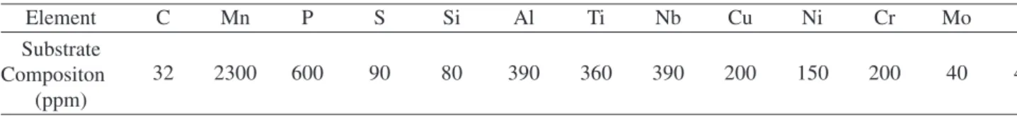
Table 1. Chemical composition of the galvanized steel sample (information provided by the sample supplier).
Element C Mn P S Si Al Ti Nb Cu Ni Cr Mo N
Substrate
32 2300 600 90 80 390 360 390 200 150 200 40 40
Compositon (ppm)
Table 2. Process conditions of the galvanized steel sample (infor-mation provided by the sample supplier).
Sample Steel Effective Coating
ID Substrate Bath Al (wt.%) Weight (g/m2)
time-temperature profile is shown in Fig. 1. The tempera-ture increases rapidly and eventually reaches a stable value. The diffractometer was set up to switch between the high temperature peaks of two selected phases, while the tem-perature increased from room temtem-perature to the stable working temperature. A total of 80 images, 40 in each posi-tion, was obtained during the thermal treatment. The acqui-sition rate was one image every 2 min, with 30 s image exposure, at each position.
2.4. Processing and Analysis of the Sequence of X-Ray Images
Figure 2 shows a typical X-ray image obtained during the in situ annealing. The images consist of a set of bright spots and, in some regions, of clusters of spots on a dark background.
From a qualitative point of view, these images provide information about the appearance or disappearance of phases that diffract at the particular 2θ values used. Digital movies were created to help the user visually identify specific clus-ters and analyze their dynamics.
From a quantitative point of view, the sequences of im-ages can be used to evaluate the evolution of the amount of the studied phases as a function of temperature. Image analy-sis routines were developed under the Digital Micrograph12
program to measure the integrated pixel intensity for user-selected windows in the images. Thus, the time evolution of pixel clusters associated to specific phases were measured and the appearance or disappearance of these phases was analyzed.
It must be noted that the images were captured at a fixed time frequency while the temperature increased. Thus, dur-ing the heatdur-ing part of the cycle, the captured images repre-sent phases that get into and out of diffraction condition due to thermal expansion. Once the stable temperature is reached, it is assumed that no further peak displacement takes place and any change in the images is due to the dynamics of phase transformations.
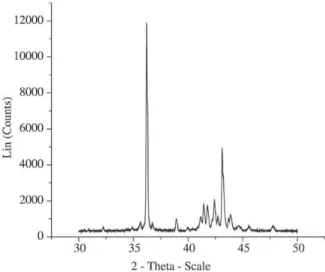
3. Results and Discussion
The choice of phases to follow is not an easy task, as the diffraction spectrum of this kind of material is very com-plex. See Fig. 3, which presents a typical spectrum obtained at room temperature. In the present work a first attempt was made at following two phases simultaneously: the η phase (2θ = 43.28°, λ = 1.54), and one of the Fe-Zn intermetallic phases (2θ = 44.80°, λ = 1.54). To determine the peak posi-tions at high temperature a spectrum was obtained with the scintillator at the stable working temperature.
At first sight, a peak at 2θ = 43.16° was attributed to the
η phase. However, further analysis showed that this peak corresponded to a new phase, formed during heat treatment.
Figure 2. Typical X-ray image obtained with the MAXIM tech-nique.
This made it very difficult to follow the η phase and the experiment was simplified to follow just the Fe-Zn phase, with a high temperature peak at 2θ = 44.44°.
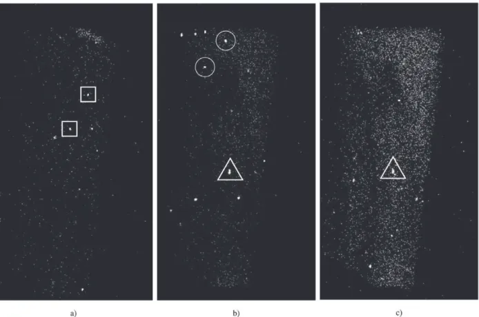
Figure 4 shows three images in the sequence for 2θ = 44.44°. It is difficult to analyze it because clusters with different characteristics are present. At least three kinds of clusters can be identified:
• Clusters that appear and disappear before the stable working temperature is reached. These clusters prob-ably correspond to a phase that gets into and out of diffraction condition due to lattice parameter variation. These clusters do not provide information regarding phase transformations (indicated by squares in Fig. 4) • Clusters that appear after the working temperature is reached and that remain until the end of the treatment. These clusters can represent two different situations: (a) A Fe-Zn phase that appears due to the heat treat-ment and that remains stable until the end of the pro-cedure. (b) Contribution of the Fe from the substrate that becomes stronger as Zinc from the coating evapo-rates at higher temperatures, as the treatment was done
under vacuum (indicated by triangles in Fig. 4). • Clusters that appear after the working temperature is
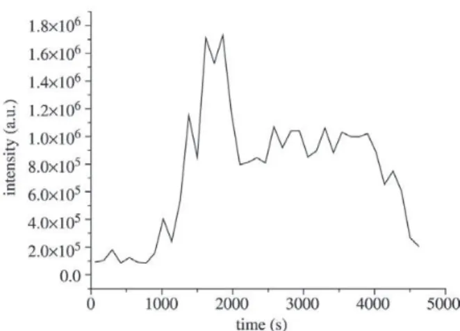
reached and disappear before the end of the treatment. These are the most probable candidates to represent a true phase transformation of Fe-Zn phases. As the ap-pearance-disappearance process occurs at constant tem-perature, it cannot be attributed to changing diffraction conditions due to lattice expansion. More likely, it rep-resents the appearance of a Fe-Zn phase with a diffrac-tion peak at 2θ = 44.44° that subsequently transforms into another phase, with a different diffraction condi-tion (indicated by circles in Fig. 4). Figure 5 shows a plot of the integrated intensity for the whole image as a function of heat treatment time. The plot reveals an in-crease of the integrated intensity in the images obtained with the diffractometer set at 44.44°.
One can only speculate about which Fe-Zn phase is grow-ing. The most likely are the ζ phase (2θ = 44°) or the δ
phase (2θ = 44.3°). Taking into account the ζ is a transient phase it can be proposed that the peak under observation is related to this phase.
Due to the geometry of the experimental set-up, only a fraction of the phase under analysis will contribute to the diffracted image. This contribution comes from those grains that happen to be favorably oriented to satisfy the Bragg condition.
4. Conclusions
The recently introduced MAXIM technique allows the construction of an X-ray image displaying the origin of the diffracted beam. Therefore, it can be used to follow the spa-tial distribution of phases on the sample surface. During an in situ experiment, the technique is able to follow the ap-pearance and disapap-pearance of phases. In this work, it was possible to develop a series of routines for the analysis and interpretation of the images generated from the experiments using this technique.
With the MAXIM technique, it was possible to directly follow the evolution of Fe-Zn phases in the galvanized coat-ing durcoat-ing a heat treatment. The technique may thus com-plement conventional microstructural analysis, by SEM or TEM, which supplies information about the coating at the end of the heat treatment. Therefore, fundamental informa-tion about the initial and intermediate stages of the transfor-mation can be obtained.
The study of galvanized samples submitted to in situ an-nealing in the solid state and analyzed with the MAXIM tech-nique and image processing leads to following conclusions: • The technique was able to follow the appearance and disappearance of phases with spatial localization. In the present work, the appearance of a Fe-Zn phase during the heat treatment was observed.
• In-situ heat treatments allowed following the transfor-mation sequence. An experimental difficulty to be con-sidered is the variation of the peak position during
heat-ing, which makes it difficult to follow the peaks along this stage. This becomes more critical when the time for formation or disappearance of a phase is relatively short. • Since the technique accumulates all information along the experiment, it allows one to follow the appearance and/or disappearance of one phase through the analy-sis of a specific region.
Acknowledgements
The authors would like to acknowledge CANMET (Canada Centre for Mineral and Energy Technology) through Dr S. Dionne and Companhia Siderúrgica Nacional, for pro-viding the samples, and CAPES and CNPq for financial support.
References
1. Guttmann, M. Diffusive Phase Transformation in Hot Dip Galva-nizing. Mat. Sc. Forum, v. 155, p. 527-548, 1994.
2. Jordan, C.E.; Goggins, K.M.; Marder, A.R. Interfacial Layer De-velopment in Hot-Dip Galvanneal Coatings on Interstitial Free (IF) Steel. Metallurgical and Materials Transactions, v. 25A, p. 2101-2109, 1994.
3. Jordan, C.E.; Marder, A.R. Morphology Development in Hot-Dip Galvannealing Coatings. Metallurgical and Materials Transactions, v. 25A, p. 937-947, 1994.
4. Marder, A.R. The Metallurgy of Zinc-Coated Steel. Progress in Materials Science, v. 45, p. 191-271, 2000.
5. Faderl, J.; Strutzenberger, J.; Fisher, W. Galvannealed Steel Sheet: 10 Years of Experience on Product and Process Improvement, In: Galvatech. 2001, Brussels, Belgium. Proceedings of the 5th Inter-national Conference on Zinc and Zinc Alloy Coated Steel Sheet, p. 385-392, 2001.
6. Mcdonald, F.E.J.; Gleeson, B. The Inhibiting Effect of Aluminum during the Galvanization of Iron Steel. In: Con. Proceedings of Materials Research, III. Australia, p. 32-36, 1996.
7. Komatsu, A.; Andoh, A.; Uchida,Y. Initial Stage of Formation of Interfacial Alloy Layers in Hot-Dip Galvanizing. In: Galvatech. 2001, Brussels, Belgium. Proceedings of the 5th International Con-ference on Zinc and Zinc Alloy Coated Steel Sheet, p. 337-344, 2001.
8. Syahbuddin, T.; Munroe, P.R.; Gleeson, B.; See, J.B. Effect of 0.1 and 0.2wt%Alluminium Additions to Zinc on the interdiffusion be-tween Zinc and Iron at 400 °C. In: Con. Proceedings of Materials Research, III, Australia, p. 37-40, 1996.
9. Wroblewski, T.; Claub, O.; Crostack, H.-A.; Ertel, A.; Fandrich, F.; GENZEL, C.; Hradil, K.; Ternes, W.; Woldt, E. A new diffractometer for Materials Science and imaging at HASYLAB beamline G3. Nu-clear Instruments and Methods in Physics Research, v. 428, p. 570-582, 1999.
10. Wroblewski, T.; Geier, S.; Hessmer, R.; Schreck, M.; Rauschenbach, B. Rev. Sci. Instr., v. 66, p. 3560, 1995.
11. Faria, M.I.S.T.; Assunção, F.R.C.; Paciornik, S.; Wroblewski, T.
Análise do Revestimento Galvanneal por Difração de Raios-X Sensível a Posição. M & M - Metalurgia e Materiais. , v. 59, n. 532, p. 3 - 6, 2003.
12. Digital Micrograph, Gatan. Image Acquisition and Processing Software.