SOFTWARE AND HARDWARE CONTROL OF A HYBRID ROBOT FOR
SWITCHING BETWEEN LEG-TYPE AND WHEEL-TYPE MODES
Wagner Tanaka Botelho
∗ [email protected]Tokuji Okada
†Abeer Mahmoud
∗ [email protected]Toshimi Shimizu
†∗Course of Information Science and Engineering
Graduate School of Science and Technology, Niigata University Niigata, Japan
†Department of Biocybernetics
Faculty of Engineering, Niigata University Ikarashi 2-8050
Niigata, Japan, 950-2181
ABSTRACT
One of the objectives of the paper is to describe the hybrid robot PEOPLER-II (Perpendicularly Oriented Planetary Legged Robot) with regard to switching between leg-type and wheel-type. Our robot has an easier design and control system than other hybrid robots. The software and hardware control in the process of performing five robot tasks are considered. These are the walking, rolling, switching, turning and spinning. In the switching task, we show the control method based on minimization of total energy cost. Also, the hardware components and their interconnections are described. The graphical user interfaces utilized in the simulation and experiment are demonstrated. The walking, rolling and the switching without reverse rotation and arm motion are verified in simulation and with real robot, in addition to turning and spinning.
KEYWORDS: Mobile robots, legged robots, wheeled robots, hybrid robots.
Artigo submetido em 18/11/2009 (Id.: 01079) Revisado em 02/02/2010, 13/07/2010, 17/09/2010
Aceito sob recomendação do Editor Associado Prof. Luis Antonio Aguirre
RESUMO
Controle de Software e Hardware de um Robô Híbrido na Mudança no Modo de Locomoção Utilizando Pernas ou Rodas
O objetivo principal deste trabalho é descrever a mudança no modo de locomoção entre pernas e rodas do robô híbrido PEOPLER-II (Perpendicularly Oriented Planetary Legged Robot). A diferença entre PEOPLER-II e outros robôs hí-bridos está relacionado com a facilidade que foi projetado e também o seu sistema de controle. O robô realizará cinco ta-refas: o caminhar, a locomoção por rodas, o chaveamento en-tre os modos de locomoção com pernas e rodas, o movimento de virar para esquerda ou direita e a rotação no sentido ho-rário ou anti-hoho-rário. O chaveamento é realizado utilizando um método que reduza o custo total de energia necessária na troca entre pernas e rodas. Neste artigo serão apresenta-dos os algoritmos de controle definiapresenta-dos para cada tarefa, as especificações do hardware definidas na arquitetura do robô e as interfaces do software utilizadas na simulação e no ex-perimento. Os resultados experimentais obtidos validam a metodologia proposta.
1
INTRODUCTION
Legged robots have been considered for a long time as effec-tive on irregular ground conditions. The problem compliance control during leg impact and during the interaction between the robot and the environment is one of the central prob-lems in locomotion of legged robots (Palis e Rusin, 2004). Even though these robots are capable of traveling on un-even terrains and climb stairs, their construction is complex (Akinfiev et al., 2008). Another characteristic is their abil-ity to use different walking gaits in response to changes in terrain, traversing speed and tasks (Still et al., 2006). A new strategy to control an one-legged robot to reduce the en-ergy by the system is explained (Schammass et al., 2001). The application of Euler-Lagrange formulation in dynam-ics of a quadruped robot leg mechanism is presented in (Pizziolo et al., 2004). A hierarchic control architecture for a four legged mobile robot using fuzzy controllers and a dual-axis accelerometer is proposed in (Lima et al., 2008). The model for determination of position of a legged robot, with respect to a fixed reference system in the start of move-ment is considered in (Filho et al., 2004). The LegGen (Heinen e Osório, 2007) automatically controls stable gaits for legged robots. ANTON (Konyev et al., 2008), Katharina (Palis e Rusin, 2004), LAURON III (Gamann e Berns, 2002), RALPHY (Amaral et al., 1993), RHex (Balasubramanian et al., 2008), SILO-4 (Garcia e de Santos, 2006), Scout-II (Poulakakis et al., 2006) and Tekken2 (Kimura et al., 2007) are examples of legged robots.
Wheeled robot mechanical constructions are simpler than legged robots. They are efficient at high speed on flat ground. Also, their mechanism are simply with inherent advantages, such as high energy efficiency, low noise, etc (Botelho et al., 2009). Lages e Hemerly (1998) discussed the control laws for all classes of wheeled robots. Junior (2008) designed the robot with two wheels and a caster to navigate safety in a known environment with obstacles. The trajec-tory controllers for differential drive, wheeled robots, with the control strategies based on output feedback is presented (Borges et al., 2003). Kühne et al. (2004) proposed a full-connected, decentralized control architecture for a wheeled robot using three different types of sensors. A graphical sim-ulator is developed to provide a computational graphical tool to assists the design and analysis of control laws of wheeled mobile robots is presented in (Schroueder et al., 2005). Ex-amples of wheeled robots are described in Seelinger et al. (2002), Kim e Tsiotras (2002), Khoh e Cho (1999), Lauria et al. (2002), Lapierre et al. (2007) and Woo et al. (2007). Each robot has the name of FIDO, Khepera, LCAR, OCTO-PUS, Pekee, WMR, respectively.
Legged and wheeled robots have benefits and drawbacks. Therefore, hybrid robots can benefit from both legs and
Figure 1: Legged robot PEOPLER-I and the designed notifi-cation for PEOPLER-II in (a) and (b), respectively.
wheels to improve locomotion performance (Sonehara et al., 2004). The environmental characteristics are one of the most influential aspects to be considered in our robot. While legged locomotion would more adaptable in a wide range of terrains, wheeled locomotion is faster but only on smooth surfaces. ALDURO (Germann et al., 2005), ChariotII (Dai et al., 1995), HyLoS-II (Grand et al., 2004), Roller-Walker (Endo e Hirose, 1999), Walk’n Roll (Adachi et al., 1999), Wheeleg (Lacagnina et al., 2003), WorkPartner (Aarne et al., 2001) and the wall climbing robot (Fu et al., 2007) are exam-ples of hybrid robots.
improve the mobility of the handicapped. The traditional depot-style wheelchair found in hospitals and airports is the most common wheelchair and they are characterized for hav-ing very few adjustments and not designed for daily long-term use. However, there are some wheelchairs with many adjustable features to maximize comfort and safety to the user (Richter, 2001).
Architectural barriers still exist in many cities and buildings, and it is expensive and timing consuming, if not impossible to eliminate all of them. A wheelchair becomes useless when faced with these barriers, and as a result, there has been a number of wheelchair designs that claim to be able to climb stairs (Morales et al., 2006). The wheelchair proposed in Morales et al. (2004) was designed to enforce mechanical stability while the wheelchair is on the staircase.
Most people live, work, and play in environments that are not easily accessible to those with mobile disability. Whether indoors or outdoors, there exist man-made or natural obsta-cles that wheelchairs cannot easily negotiate. For example, a powered wheelchair is able to negotiate curbs up to 130 mm in height with the use of a rocking arm which engages the curb and lifts the front wheels up (Browning et al., 1996).
It has been known that hybrid robots have a very complex design, even more complex than legged robots. Normally, they have a complex control system and require a large num-ber of motors. Our robot PEOPLER-I (Okada et al., 2003) can be modified to become a hybrid wheelchair robot called PEOPLER-II (Okada et al., 2006), without additional mo-tors.
This paper describes the design concepts of the hybrid robot PEOPLER-II. Also, we define and explain five robot tasks and their respective control algorithm. These are the walking, rolling, switching between leg-type (L-type) and wheel-type (W-type), turning and spinning. The switching task is per-formed using the total torque minimization method (Okada et al., 2007). The hardware components that our hybrid robot is composed of and the controller interfaces utilized in the simulation and experiment are explained and shown in this paper. We present the class diagram with seven classes for the simulation and experimental interfaces. The idea used to make the communication of hardware and software control is considered. The switching task is verified in simulation and also using the PEOPLER-II, in addition to walking, rolling, turning and spinning. In the switching task, the continuity of the hip joint rotation without reversing and the constant state of the robot arm rotation are considered. These are the main results and contributions of this work.
This paper is organized as follows. Section 2 brings a brief description of the robot and the used terminology. The to-tal torque minimization method utilized in the switching task
Figure 2: Nomenclatures of the new design of PEOPLER-II.
is described in Section 3. The description of the robot tasks and the control algorithms are explained in Section 4. Hard-ware control specifications and softHard-ware control design are discussed in Section 5. Simulation and experimental results are shown in Section 6. Finally, the conclusions are presented in Section 7.
2
PEOPLER-II DESCRIPTIONS AND
TER-MINOLOGY
The first prototype, PEOPLER-I is a walking robot com-posed of 4DOFs (Degree of Freedom) utilized to walk on irregular terrain or climbing stairs as shown in Figure 1(a). Right and left sides are mechanically identical. It has four arms connected by the hip joint to each axis in the right and left robot sides. Each arm has two legs connected at the knee joint situated at the two ends of the arm. The leg posture stands for leg direction angle from the gravity direction as shown in Figure 2. The leg postures angles are same in the both directions but different in its sign because only one mo-tor drives the two legs for saving installation cost of actua-tors. That is, each leg pair automatically swing opposite with mechanical symmetry in the direction of gravity.
In total, the robot has four motors (M1, M2, M3, M4) of 120 W each as shown in Figure 1. M1 and M2 are utilized to control the left and right arms. Arms in the front and back are combined mechanically. Another two motors M3 and M4 are responsible for activating two leg pairs on the left and right, respectively. Two legs pairs located at the front and back are also combined mechanically, so that they move in synchronization.
arms and the wheels in the L-type and W-type, respectively. Therefore, additional motors are not needed. The arm is 36.5 cm long, 10.0 cm width. The 30.0 cm length with 2.5 cm width is the leg description. The outer radius of the wheel is 20.7 cm, the inner radius is 18.2 cm. The total robot weight is 107.0 kg. Finally, the robot body length, width and height are 110.0 cm, 90.0 cm and 10.5 cm, respectively. A schematic model with parameters and constants considered in this paper is shown in Figure 2. It shows the new design of PEOPLER-II on a slope standing as a L-type. Symbolic notations are as follows
c: ratio of the hip joint motor capacity to the knee joint motor capacity;
dh: projected distance of hip joint from the leg end contact on the ground;
dk: projected distance of knee joint from the leg end contact on the ground;
h: obstacle height;
H: hip joint height;
J: joint (Jh; hip joint, Jk; knee joint);
l: leg length of the robot;
L: length of the robot body (distance between front and rear hip joint axes);
r: radius of knee joint rim;
R: radius of a wheel expressed as a circular profile surrounding knee joints;
Th: torque of Jh;
Tk: torque of Jk;
W: robot weight operating at pivotal foot position;
γ: leg posture angle (a pair of legs is symmetrical in the direction of gravity);
θ: arm angle from the robot’s front direction;
θr: arm angle from the front horizontal direction (θr=θ−θs);
θs: inclination angle of the road surface.
3
METHOD FOR MINIMIZING THE TOTAL
ENERGY COST
In order to make the robot stand always, we consider the ki-netic related to the torques at joints Jh and Jk. Figure 2, we may derive the following equations.
Th = W dh=W(rcosθr−lsinγ), (1)
Tk = W dk =W lsinγ, (2)
H = rsinθr+lcosγ. (3)
The total energy cost, E, is evaluated by
E = (Th)
2
+ (cTk)
2
. (4)
To make the value ofEminimal it follows that
∂E ∂θr
= 0. (5)
Using Eqs. 1 and 2, we find the 6thorder equation of un-known parametersinθr, then we have
∂E ∂θr
= r4
(A2
+ 2A−3) sin6
θr−2Hr
3
(2A2
+ 3A−5)
× sin5
θr+r
2
{6H2(A2+A−2)−(r2+l2)
× (A2
+ 2A−3)}sin4
θr−2Hr{H
2
(2A2
+A−3)
− r2(2A2+ 3A−4)−l2(A2+A−3)}sin3
θr + [H2
{H2
(A2
−1)−r2
(6A2
+ 6A−7)−l2
(A2 − 2)} −r2
{r2 −l2
(A2
+ 2A−1)} −l4
] sin2
θr + 2Hr{H2(2A2+A−1) +r2−l2(A2A−1)} × sinθr−H
2 {H2
A2
+r2 −l2
A2
}= 0, (6)
where
A = c2
+ 1. (7)
Solving Eq.6 is not simple, but graphical tracing and explo-ration gave the angleθrthroughsinθr. With this,γis calcu-lated from Eq.3.
4
ROBOT TASK CONTROL ALGORITHM
The user, computer and PEOPLER-II have been defined as actors in our system. The user interacts with the system via command line. The computer interacts with the User via Graphical User Interface (GUI), and the PEOPLER-II is the main actor that receives tasks to be performed. The de-scriptions of the robot tasks and the control algorithm are described.
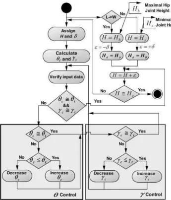
Figure 3: The activity diagram of the switching task.
4.1
Walking/Rolling tasks
PEOPLES-II moves using L-type and W-type. However, the right and left sides are controlled independently. Therefore, in order to avoid rolling and pitching a balanced control be-tween both sides is needed. Also, we check whether one of each leg pair locates at upside on the ground because down-side candidate is impractical. Specifically, the case when two leg ends touch the ground at the same time should be avoided because the ground friction prevents the robot’s sit-ting or standing. In the L-type, the robot is allowed to walk of constant γ, with short, standard or long strides (Okada et al., 2005). On the other hand, the legs have a tendency to direct upward so that all of the legs do not touch the ground in the W-type (Okada et al., 2006).
4.2
Switching task
In order to make the switch comfortably with less shock to the robot body, we separate the robot control into three phases to generate transitional adaptation in the switching task (Botelho et al., 2009). The steps taken by the robot are shown in Figure 4. The locomotion is switched from L-type to W-type from top to bottom. We divided the switching task in three phases. The first, second and last phases are the L-type, Switching and W-type, respectively. During the
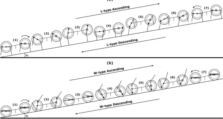
Figure 4: Motion sequence to make the switching task in a stable fashion.
L-type the value ofγ is fixed, as shown in configurations (1)-(2). In the switching period the robot is able to stand or sit in configurations (3)-(4) and (4)-(3), respectively. In the sitting phase, the motions are continues until two landing contacts on the ground. It is calledchange round configu-ration(CRC). These landing happen when the robot stands from rolling or sits from walking as shown in (4). After that, transitional adaptation is needed in the rolling phase to make the connection between the rolling to the regular motion of W-type, as shown in configurations (5)-(6).
We propose three methodologies for doing preparatory tasks before starting the switching task (Okada et al., 2008). Each is characterized byθandγ. The values ofγare calculated according to the rotation ofθin the switching task. In the first methodology,θandγare variables solving the 6th
or-der Eq.6 and using Eq.3, respectively. It is the method for minimizing total energy cost explained in the Section 3. In the second methodology,θis constant andγis variable. The third methodologyγ is constant and θ is variable. But, it is considered not practical because of the high energy con-sumption. In order to evaluate the energy cost for driving the two joint motors in the first methodology, we take into con-sideration the ratio of the energy cost for producing the Jh torque in comparison to the cost for producing the Jktorque. The values of θ andγ are uniquely calculated in order to reach the CRC. In this paper, we consider the first and sec-ond methodologies in the simulation and experimental veri-fication.
uti-Figure 5: The activity diagram of the turning task.
lized to control the robot in the switching task. We use the notations: θt,θc andγt,γc for the target, current arm and leg posture angles, respectively. Also,δ,Hb,HsandHeare the pre-defined incremental constants, maximalH, minimal
Hand the indicator of the end hip joint height, sequentially. The first step is to assignHaccording to the switching task. For example, if the switch is from L-type to W-type (L→W) thenH receivesHb andHewhich is equal toHsin the sit down phase. In the reverse switch,H is equal toHs. Also,
He is same to Hb andH increases until reach the L-type. Next, theH andδare assigned andθtandγtare calculated. The input data concerned withθ andγare verified by po-tentiometers. Ifθc ∼= θt andγc ∼= γtthenH increase or decrease and is assigned again to calculate the nextθt and
γt. After that, theγcontrol is verified. Using the same idea, forγc andγt. Next, the input data is verified. This idea is proceeded untilHis equal toHe.
4.3
Turning task
In the turning task, the amplitude of a stride and the rotation speed in the right/left sides are the main points to be con-sidered for the L-type and W-type, respectively. Evidently, the legs are easily inclined and used to determine the amount of walking stride (Okada et al., 2006). That is, the distance between two leg ends located at the same Jh when the leg pair makes a landing together. The main idea is to con-trol the amount of stride to make the robot walk forward or backward with short, standard and long strides (Okada
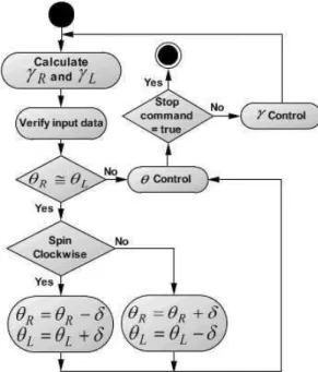
Figure 6: The activity diagram of the spinning task.
et al., 2004; Okada et al., 2005). Also, the ability of chang-ing the amount of stride is important to make the robot walk over obstacles without bumping into them. The robot turns right by making a long stride to the left and a short to the right (Mahmoud et al., 2008). However, the turning task for the W-type is performed when the increment ofθon the right side is less than on the other side.
Figure 5 shows the activity diagram utilized in the turning by L-type. The amount ofγin the right (γR) and left (γL) sides of the robot is determined as a periodical function of
θ (Okada et al., 2005). The currentγc,θR on the right and other sideθLare verified as input data. The synchronization is requested, therefore if θR ∼= θL and the task is to turn right then the values ofγRandγLare short and long strides, respectively. Otherwise, theθcontrol explained in the Figure 3 is asked to makeθR∼=θL.
4.4
Spinning task
The spinning task is performed when the robot turns around its body center. Theθ in the right and left arms are driven in opposite directions in synchronization (Mahmoud et al., 2008).
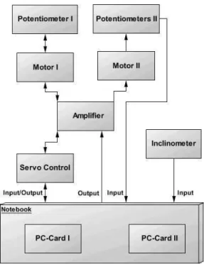
Figure 7: Diagram for hardware specifications.
5
CONTROLLER IMPLEMENTATION
This section presents an overview of the hardware and soft-ware control implementation of PEOPLER-II. The simula-tion and experimental interfaces with the class diagrams are explained. The communication between the hardware and software is also explained.
5.1
Hardware control specifications
Our hybrid robot is composed of a notebook with two PC-Cards, servo control, amplifier, motors, potentiometers and inclinometer. A diagram of the whole system is seen in Fig-ure 7. The notebook and other components are represented by the cube and rectangular box, respectively.
The Athlon XP-M 1400 1.2GHz and 256 RAM with two Cardbus interfaces connect the two digital/analog I/O PC-Cards of ADA16-32/2(CB)F (CONTEC Co., Ltd., 2008). The bus mastering included in the Cardbus allows a con-troller on the bus to communicate with other devices without going through the CPU. It transfers analogue input, analogue output, digital input and digital output data and synchronizes them with clock signal. The eight legs and four Jhs are con-trolled by the PC-Card I and PC-Card II, respectively. The PC-Card I receives and sends the data through the servo con-trol. However, the PC-Card II is directly connected to the amplifier and also receives the input data from the
inclinome-Figure 8: 2-D Simulation environment.
Figure 9: Experimental environment.
ter AccuStar SD-20 (Pacico).
The Motor I and Motor II on the right side of the robot are linked to three potentiometers, the first CPP-45 of 5kΩ is utilized to get the currentγand the other two HP-16 of 10kΩ are responsible for gettingθ. The same number of motors and potentiometers are utilized to control the left side. These data are transmitted to the PC-Cards as an input data.
5.2
Software control design
Figure 10: Class diagram for the PEOPLER-II application.
5.2.1 Simulation interface
Due to its symmetry on the right and left sides, and controlled in synchronization in motion of the front and rear structures, PEOPLER-II can be studied considering only the side view. Therefore, we developed a software in JAVA to simulate in 2-D the robot locomotion control, as shown in Figure 8. It pro-vides a GUI that represents an environment in which we eas-ily create, set and edit the configurations of our robot to per-form the walking, rolling and switching tasks. The smooth-ness of the robot is also considered in our application. We tried to imitate the overall control of the robot with its real characteristics. The synchronization between the front and back, number of legs and wheels are also defined in the soft-ware. It is useful to imagine control scenarios without having to use the real prototype. On the bottom, several buttons are available for software interaction.
5.2.2 Experimental interface
Figure 9 shows the interface utilized to control the PEOPLER-II in the experiment. Some parameters are shown in the interface. For instance, the design notifications ofR,
r,L,land the current input data ofθ,γ,H.
5.2.3 Class diagrams
The class diagrams show an object oriented structure in-cluding attributes, their operations, and relationships to other
Figure 11: Communication between the software and hard-ware control.
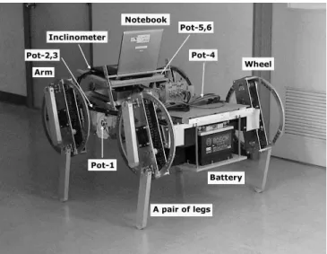
Figure 12: The prototype of the PEOPLER-II.
classes (Kim et al., 2006). Also, it describes the static view of an application (Purchase et al., 2001). The dependence between two classes is drawn as a line arrow characterized by a label showing the relation type, for instance the Inter-face1class is bound up together withLocomotionclass be-cause it contains an attribute of type drawRobot (Murnolo et al., 2001), as shown in Figure 10.
The application consists of five classes for simulation and four classes for experimental verification. However, two classes are designed to be reusable as components of other applications. These are theLSM(Least Square Method) and
Figure 13: L-type with a fixed value ofγ in (a) and W-type generated using Fourier function in (b) on the slope ofθs = 10
degrees.
Interface1 is responsible for drawing the side view of PEOPLER-II. Also, it receives all the information that the user is allowed to make changes with the aim to simulate the robot motion.
Interface2creates an object of classInterface1and its nec-essary GUI.
Locomotion class receives robot specifications (R, r, l, θ
andγ) to be generated on the coordinate system.
LSMis a class responsible for returning the estimated data calculated by the LSM (Okada et al., 2006).
DerivativeMethodis a class responsible for calculatingθin the 6th
order equation (Eq.6) in the method for minimizing total energy cost.
Interface3 is responsible for designing the experimental GUI.
SingleAIclass is developed to use the driver library (API-PAC(W32)) (CONTEC Co., Ltd., 2008) supplied with the PC-Card.
5.3
Communication of hardware and
soft-ware control
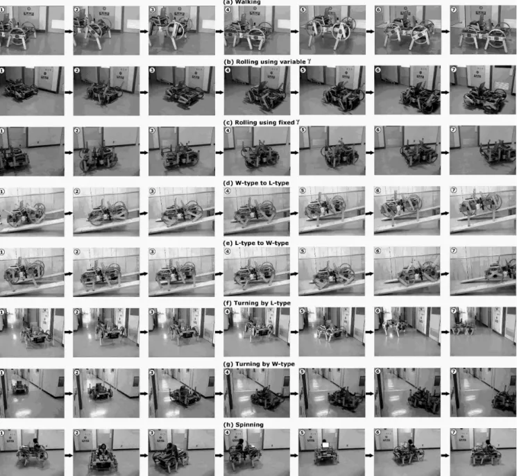
Figure 14: Experimental results in the walking, rolling using variableγ, rolling using fixedγ, switching from W-type to L-type, from L-type to W-type, turning by L-type, turning by W-type and spinning in (a), (b), (c), (d), (e), (f), (g) and (h), respectively.
6
SIMULATION AND EXPERIMENTAL
RE-SULTS IN THE ROBOT TASKS
6.1
Prototype of PEOPLER-II
Figure 12 shows PEOPLER-II photograph. The 12 V battery and the notebook are shown in the figure. The potentiometers (Pot-1, Pot-4) in the middle of the robot body and (Pot-2,3, Pot-5,6) are responsible for getting input data of γ and θ,
respectively. Also, the two-axis inclinometer is utilized to get the dataθs.
6.2
Walking
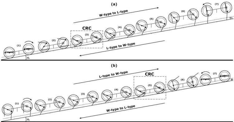
Figure 15: Optimal switching from W-type to L-type on an ascending slope and from L-type to W-type on a descending slope in (a). Optimal switching without arm motion from L-type to W-type and vice versa in (b) underθs= 10degrees.
confirmed the balanced control without rolling and pitching. It is clear to verify that the stride becomes long in the photos
1
-2,5-7 and short in3-4 in Figures 13(a) and 14(a).
These are typical characteristics when the constant value of
γis utilized.
6.3
Rolling
In the W-type, we obtained a faster, more stable and easy to control robot motion than L-type. Figures 13(b), 14(b) and 14(c) show the W-type using a variableγ calculated as a Fourier function ofθandγisπradian, respectively. Con-figurations (1)-(7) in Figure 13(b) are the same as to photos
1
-7 in Figure 14(b).
6.4
Switching without reverse rotation
The simulation results shown in Figure 15(a) are obtained by the first methodology. In this methodology,θandγ are considered as variables and are solved by minimizing total energy cost explained in Section 3. The optimal switching from W-type to L-type on an ascending and from L-type to W-type on a descending slope underθs= 10degrees is per-formed in the same hip joint direction without a reverse rota-tion in the configurarota-tions (1)-(7) and (7)-(1), respectively.
Figure 14(d) shows the sequential experimental photos in the switching from W-type to L-type on an ascending slope. The inclinometer recognizesθs = 10degrees. It is performed by the activity diagram explained in Figure 3. The reverse motion from7 to1 makes the switch from L-type to
W-type on a descending slope. Photos from3 to7 correspond
to the same sequence in the simulation shown in Figure 15(a). The photo3 is the CRC.
6.5
Switching without arm motion
Figure 15(b) shows the simulation results using a fixed value ofθand variableγ. That is, the second methodology. Con-figurations (1)-(7) and (7)-(1) illustrate the switching from L-type to W-type on an ascending and vice versa on a de-scending slope, respectively. Because of the reversible se-quence of motion when switching between W-type to L-type on an ascending and L-type to W-type on a descending, it can be understood from the configurations (5)-(1) and (1)-(5), re-spectively. The CRC is the configuration (5).
The experimental results concerned with the simulation in Figure 15(b) is illustrated in Figure 14(e). The photos3,
4
,5,6 and7 are almost the same as to configurations
is seen in5.
6.6
Turning and spinning
PEOPLER-II turns left by making a long stride right and a short stride left, as explained in Figure 5. Figure 14(f) shows the turning by L-type. However, Figure 14(g) shows the W-type turning right when the increment ofθon the right side is less than on the other side. Finally, using the control algo-rithm in Figure 6 the right and left arm motion is in opposite directions in synchronization in the spinning task, as shown in Figure 14(h).
7
CONCLUSIONS
In this paper we showed the adaptation of our legged robot I to become a renovated hybrid robot PEOPLER-II. It is composed of 4DOFs; one arm set and one leg set for right and left sides. In total, it has only 4 motors, i.e. two motors for driving right and left hip joints and another two motors for rotating left and right legs. The hip joints and legs at front and back were mechanically synchronized.
The robot was able to walk, roll, switch, turn and spin. These were the robot tasks. The control algorithms of these tasks were explained. The control method for minimizing energy consumption was considered in the switching task. The hard-ware components and the connections between them were discussed. Also, we described the GUI utilized in the simu-lation and experiment. The structure of the system using the JNI framework was carried out in order to make the commu-nication between the software and the robot. The simulation results in the walking, rolling and switching were showed. In the switching task, we took into considerations the same hip point direction and the constant state of the arm rotation. Also, we succeeded in demonstrating the robot tasks using the PEOPLER-II. These are the main goals achieved in this research.
Further work in the switching with turning and spinning is being considered to enhance the application of the robot. As we showed in the results that the robot is able to turn and spin, the switching with these tasks is also possible. If the leg pairs are controlled independently, the legs are able to be folded completely within the wheel frame. Therefore, the new design of the PEOPLER-II with 6DOFs is considered to reduce the vertical swing in L-type and to make the legs completely fold with the wheel frame in the W-type. In order to verify the vertical swing and the variation of the robot’s inclination, the experimental trajectory of the robot center is considered in the next work. The PEOPLER-II is only a prototype for developing the hybrid robot. However, we believe that PEOPLER-II will be able to carry a human body.
Finally, we thank the Japanese Government Scholarship Pro-gram from the Ministry of Education, Culture, Sports, Sci-ence, and Technology (MONBUKAGAKUSHO) for the sup-port of this research.
REFERENCES
Aarne, H., Ilkka, L., Miso, M. e et al. (2001). Robot motion by simultaneously wheel and leg propulsion, Proc. of 4th Int. Conf. on Climbing and Walking Robots (CLAWAR), Germany, pp. 1013–1019.
Adachi, H., Koyachi, N., Arai, T. e et al. (1999). Mechanism and control of a leg-wheel hybrid mobile robot,Proc. of IEEE/RSJ Int. Conf. on Intelligent Robots and Systems (IROS), Korea, pp. 1792–1797.
Akinfiev, T., Fernandez, R. e Armada, M. (2008). De-sign of wheeled climbing robot with changeable struc-ture,Proc. of 11th Int. Conf. on Climbing and Walking Robots (CLAWAR), Portugal, pp. 549–554.
Amaral, P. F. S., Gamah, H. E., Fontaine, J. G. e Rabit, J. (1993). RALPHY - um robô móvel eletropneumático com quatro pernas,I Congresso Iberoamericano de In-genieria Mecânica.
Balasubramanian, R., Rizzi, A. A. e Mason, M. T. (2008). Legless locomotion a novel locomotion technique for legged robots,J. of Robotics Research27(5): 575–594.
Booch, G., Jacobson, I. e Rumbaugh, J. (1996). The uni-fied modeling language for object-oriented develop-ment,Documentation Set Version 0.91 Addendum UML Update - Rational Software Corporation, USA.
Borges, G. A., Lima, A. M. N. e Deep, G. S. (2003). Con-troladores cinemáticos de trajetória para robôs móveis com tração diferencial,VI Simpósio Brasileiro de Au-tomação Inteligente (SBAI 2003), pp. 787–792.
Botelho, W. T., Okada, T. e Shimizu, T. (2009). Smooth switching phases control with simulation and experi-mental verication of a hybrid mobile robot from leg-type to wheel-leg-type and vice versa, Journal of Cyber-netics and Systems, International Science Press, ISSN 0974-54592(2): –.
Browning, D. R., Trimble, J., Song, S. e et al. (1996). Legged mobility a wheelchair alternative, http://www.evl.uic.edu/drew/leggs.htm.
CONTEC Co., Ltd.(2008).url: http://www.contec.com.
Endo, G. e Hirose, S. (1999). Study on roller-walk (sys-tem integration and basic experiments),Proc. of IEEE Int. Conf. on Robotics and Automation (ICRA), United States, pp. 2032–2037.
Filho, A. B., Amaral, P. F. S., Pinto, B. G. M. e Lima, L. E. M. (2004). Uma metodologia para a localiza-ção aproximada de um robô quadrúpede,XV Congresso Brasileiro de Automática.
Fu, Y. L., Li, Z., Yang, H. J. e et al. (2007). A wheeled wall-climbing robot with a climbing leg,Proc. of 10th Int. Conf. on Climbing and Walking Robots (CLAWAR), Singapure, pp. 55–64.
Gamann, B. e Berns, K. (2002). Local navigation of lau-ron iii walking in rough terrain,Proc. of 5th Int. Conf. on Climbing and Walking Robots (CLAWAR), France, pp. 509–514.
Garcia, E. e de Santos, P. G. (2006). On the improve-ment of walking performance in natural environimprove-ments by a compliant adaptive gait,IEEE Trans. on Robotics
22(6): 1240–1253.
Germann, D., Hiller, M. e Schramm, D. (2005). Design and control of the quadruped walking robot ALDURO, Proc. of Int. Symp. on Automation and Robotics in Con-struction (ISARC), Italy, pp. 1–8.
Grand, C., BenAmar, F., Plumet, F. e et al. (2004). De-coupled control of posture and trajectory of the hybrid wheel-legged robot Hylos,Proc. of IEEE Int. Conf. on Robotics & Automation, United States, pp. 5111–5116.
Heinen, M. R. e Osório, F. S. (2007). Controle inteligente do caminhar de robôs móveis utilizando algoritmos genéticos e redes neurais artificiais, XXVII Congresso da SBC - VI Encontro Nacional de Inteligência Artifi-cial (ENIA), pp. 952–961.
Junior, S. G. O. (2008). Desenvolvimento de um robô com rodas autônomo, Master’s thesis, Universidade Federal do Rio de Janeiro - COPPE/UFRJ.
Khoh, K. C. e Cho, H. S. (1999). A smooth path track-ing algorithm for wheeled mobile robots with dy-namic constraints,J. of Intelligent and Robotic Systems
24(4): 367–385.
Kim, B. e Tsiotras, P. (2002). Controllers for unicycle-type wheeled robots: Theoretical results and experimental validation, IEEE Trans. on Robotics and Automation
18(3): 294–307.
Kim, M., Kim, S., Choi, M. e et al. (2006). UML-based ser-vice robot software development: A case study,Proc. of 28th Int. Conf. on Software Engineering, ACM, China, pp. 534–543.
Kimura, H., Fukuoka, Y. e Cohen, A. H. (2007). Adap-tive dynamic walking of a quadruped robot on natural ground based on biological concepts,J. of Robotics Re-search26(5): 475–490.
Konyev, M., Palis, F., Zavgorodnity, Y. e et al. (2008). Walking robot “ANTON”: Design, simulation, exper-iments,Proc. of 11th Int. Conf. on Climbing and Walk-ing Robots (CLAWAR), Portugal, pp. 922–929.
Kühne, F., Claro, C. A. H., Suess, S. R. e Lages, W. F. (2004). Estimação e controle da posição de um robô móvel uti-lizando filtro de kalman descentralizado,XV Congresso Brasileiro de Automática.
Lacagnina, M., Muscato, G. e Sinatra, R. (2003). Kinemat-ics, dynamics and control of a hybrid robot wheeleg,J. Robotics and Autonomous Systems45(3): 161–180.
Lages, W. F. e Hemerly, E. M. (1998). Controle em coor-denadas polares de robôs móveis com rodas,XII Con-gresso Brasileiro de Automática.
Lapierre, L., Zapata, R. e Lepinay, P. (2007). Combined path-following and obstacle avoidance control of a wheeled robot,J. of Robotics Research26(4): 361–375.
Lauria, M., Piquet, Y. e Siegwart, R. (2002). OCTOPUS: an autonomous wheeled climbing robot, Proc. of 5th Int. Conf. on Climbing and Walking Robots (CLAWAR), France, pp. 315–322.
Liang, S. (1999). The java native interface programmer’s guide and specification,Published by Addison-Wesley.
Lima, L. E. M., Amaral, P. F. S. e Filho, A. B. (2008). Cont-role da estabilidade de equilíbrio para um robô quadrú-pede com uso de lógica nebulosa,VIII Conferência In-ternacional de Aplicações Industriais - Induscon.
Mahmoud, A., Okada, T. e Shimizu, T. (2008). Circular trajectory simulation analysis of a rotating four-legged robot, Proc. of Int. Conf. on Intrumentation, Control and Information Technology (SICE), Japan, pp. 691– 694.
Morales, R., Feliu, V., Gonzalez, A. e et al. (2004). Kinemat-ics of a new staircase climbing wheelchair,Proc. of 7th Int. Conf. on Climbing and Walking Robots (CLAWAR), Spain, pp. 249–264.
Morales, R., Feliu, V., Gonzalez, A. e et al. (2006). Kine-matic model of a new staircase climbing wheelchair and its experimental validation,J. of Robotics Research
Murnolo, E., Moratto, S., Nolich, M. e et al. (2001). Object oriented design of a mobile robot using UML, Proc. of 23th Int. Conf. Information Technology Interfaces, Croatia, pp. 608–613.
Okada, T., Botelho, W. T. e Shimizu, T. (2006). Compatible use of a legged robot as a wheeled robot and its demon-strative simulation,Proc. of 9th Int. Conf. on Climbing and Walking Robots (CLAWAR), Belgium, pp. 34–44.
Okada, T., Botelho, W. T. e Shimizu, T. (2007). Leg control for changing locomotion between leg-type and wheel-type base on effective use of total power,Proc. of 10th Int. Conf. on Climbing and Walking Robots (CLAWAR), Singapure, pp. 365–372.
Okada, T., Botelho, W. T. e Shimizu, T. (2008). Walking gait control for making smooth locomotion mode change of a legged and wheeled robot, Proc. of 11th Int. Conf. on Climbing and Walking Robots (CLAWAR), Portugal, pp. 711–719.
Okada, T., Hirokawa, Y. e Sakai, T. (2003). Development of a rotating four-legged robot, PEOPLER for walking on irregular terrain,Proc. of 6th Int. Conf. on Climbing and Walking Robots (CLAWAR), Italy, pp. 593–600.
Okada, T., Hirokawa, Y., Sakai, T. e Shibuya, K. (2004). Syn-chronous landing control of a rotating 4-legged robot, PEOPLER, for stable direction change, Proc. of 7th Int. Conf. on Climbing and Walking Robots (CLAWAR), Spain, pp. 85–96.
Okada, T., Sakai, T., Shibuya, K. e Shimizu, T. (2005). Hip joint control of a legged robot for walking uniformly and the self-lock mechanism for compensating torque caused by weight, Proc. of 8th Int. Conf. on Climb-ing and WalkClimb-ing Robots (CLAWAR), United KClimb-ingdom, pp. 197–204.
Palis, F. e Rusin, V. (2004). Adaptive impedance control of legged robot, Proc. of 11th Int. Conf. on Power Elec-tronics and Motion Control, Latvia.
Pizziolo, T. A., de S. Martins-Filho, L., de Resende, P. e Sil-vino, J. L. (2004). Análise de simplificação na mod-elagem dinâmica aplicada a robôs quadrúpedes, SBA Controle & Automação15(3): 301–308.
Poulakakis, I., Papadopoulos, E. e Buehler, M. (2006). On the stability of the passive dynamics of quadrupedal running with a bounding gait,J. of Robotics Research
25(7): 669–687.
Purchase, H. C., Colpoys, L., McGill, M. e et al. (2001). UML class diagram syntax: An empirical study of com-prehension, Australian Symposium on Information Vi-sualisation, Australia, pp. 113–120.
Richter, W. M. (2001). The effect of seat position on manual wheelchair propulsion biomechanics: a quasi-static mode-based approach,Medical Engineering and Physics23: 707–712.
Schammass, A., Caurin, G. A. P. e Valente, C. M. O. (2001). Control of a one-legged robot with energy savings,J. of the Brazilian Society of Mechanical Sciences23(1): 41– 48.
Schroueder, G. N., Espíndola, D. B., Botelho, S. S. C., Bi-cho, A. L. e Oliveira, V. M. (2005). Simulador gráfico para controle de robôs móveis omnidirecionais, INFO-COMP - J. of Computer Science4(4): 38–47.
Seelinger, M., Yoder, J., Baumgartner, E. T. e et al. (2002). High-precision visual control of mobile manipulator, IEEE Trans. on Robotics and Automation18(6): 957– 965.
Sonehara, K., Yamamoto, T., Koichi, T. e et al. (2004). De-velopment of breadboard model for locomotion of 3-leg wheeled type robot,Tech. Rep. of IHI.
Still, S., Hepp, K. e Douglas, R. J. (2006). Neuromorphic walking gait control,IEEE Trans. on Neural Networks
17(2): 496–508.