Port structures – the distribution of forces on
infrastructure due to mooring and berthing of vessels
Estruturas portuárias – distribuição de esforços na
infraestrutura devidos à amarração e atracação de
embarcações
Abstract
Resumo
This work presents a study on the project actions required for the design and analysis of port structures, with regard to the impacts of mooring and berthing of vessels. This study sought to conduct a literature review, with emphasis on technical standards and codes, encompassing both national and international publications, including the Brazilian Standard NBR 9782/1987, the British Standard BS 6349, and the German Standard EAU 2004, in addition to the recommendations of the Permanent International Association of Navigation Congresses (PIANC 2002), and those of Jayme Mason (1982) in “Port Works”. The design procedures proposed by these diferent references regarding the computation of forces in -duced by mooring and berthing of vessels were evaluated in this work. Additionally, a case study of a port’s substructure was carried out, and a comparative analysis of the results, obtained with each recommendation of the aforementioned publications, was performed. The results showed a remarkable dispersion, revealing that the standards used strongly inluence the design loads of port structures.
Keywords: maritime facilities, mooring, berthing, vessels.
O presente trabalho apresenta um estudo sobre as ações de projeto a serem consideradas no dimensionamento e análise de estruturas portuá-rias, no tocante às solicitações devidas à amarração e atracação de embarcações. O estudo buscou fazer um levantamento sobre o assunto na literatura nacional e internacional, com ênfase nas normas técnicas, em especial a NBR 9782/1987, a norma inglesa BS 6349 e a norma alemã EAU 2004, além das recomendações da Permanent International Association of Navigation Congresses (PIANC 2002) e de Mason (Jayme, 1982) em sua publicação Obras Portuárias. Foram estudados os métodos de cálculo dos esforços devido à amarração e atracação de embarcações segundo as diversas referências. Posteriormente realizou-se uma análise comparativa entre os resultados dos esforços obtidos com cada mé-todo de cálculo em um estudo de caso de uma estrutura, para o qual é analisada a sua infraestrutura. Os resultados demostraram uma notável dispersão entre os métodos utilizados nos cálculos, evidenciando uma grande inluência do código normativo utilizado para as análises no di -mensionamento de estruturas portuárias.
Palavras-chave: estruturas portuárias, amarração, atracação, embarcações.
a PPGEC – Federal University of Pará, Belém, PA, Brazil; b FEC/ITEC – Federal University of Pará, Belém, PA, Brazil.
Received: 24 Apr 2015 • Accepted: 05 Sep 2016 • Available Online: 12 Jun 2017
C. COMIN a
R. M. DE SOUZA b
1. Introduction
The construction of ports and docks is among the irst major devel -opments of human civilization. The ancient civilizations had great, intuitive knowledge of their maritime facilities, which unfortunately became lost with the decline of empires and the changing of the seashores. Wood and stone ports and harbors built less than one hundred years ago are gradually being replaced by concrete and steel structures, which has extended maritime port facilities into deeper waters and exposed locations. Even so, port and dock de-signers still rely heavily on the study of past experiences to perfect their analysis and practice of contemporary projects (Gaythwaite, 2004, p. 1).
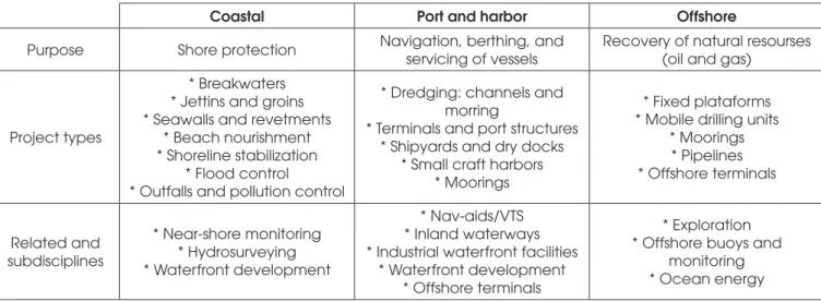
The engineering of maritime facilities includes planning, design-ing, and constructing ixed anchored structures and ixed loat -ing structures along oceanic and large river and lake shores and coasts, in addition to those works included in the ofshore cat -egory. Table 1 provides an overview of the types of structures involved in this context.
Ports are one of the most important strategic points of a country’s economy, since much of its mass production is usually shipped through them (Amador Júnior, 2006, p. 4). Maritime facilities are the vital connection between land, road, or rail transport and the waterways, and it is necessary that ships and vessels be loaded and unloaded quickly and eiciently at these sites. Some techni -cal professionals say that, generally, there is no railway without a port, especially in the case of railways designed predominantly for carrying cargo.
In the design of a port structure, a lot of information is needed to design a solution that will be able to meet the cargo handling demands, for which this structure is being designed, in an eicient manner that is also technically and economically feasible. Initially, this information depends on some general characteristics, of which the most relevant are: (i) the type of cargo to be handled in the port/ terminal; (ii) the types of ships that will operate in the area, and (iii) the local environmental conditions.
For a better understanding and in order to cover all types of mari-time structures, whether for organized ports, specialized, or gen-eral cargo terminals, we will henceforth use the term “maritime fa-cilities” to refer to the structures mentioned thus far.
The maritime facilities design criteria should be established after careful consideration of various operational, functional, and navi-gation requirements, in addition to the environmental conditions on the site, and physical and legal restrictions. Table 2 presents a summary of these considerations.
Figure 1 presents a generalization of the demands to which the structure of a maritime facility is subjected to, with an example of a pier. Among the elements listed in Table 2, we should point out the importance of evaluating the actions that ships and vessels can have on these structures, which are the object of this study and are mainly characterized by the forces that ships exert on the facilities during docking maneuvers and the forces used to secure them after berthing.
First, one must consider the impact that ships physically exert upon maritime facilities with the subsequent transmission of kinetic ener-gy from the ship to the structure, and its transformation into strain-ing energy on the structures and fenders. From the equivalence between the kinetic energy of the ships impact and the straining energy, after computing various losses and other factors that inlu -ence the process, one can infer the impact forces for scaling works and fenders (Mason, 1982, p. 88).
Second, regarding the securing forces or ship’s mooring to mari-time facilities, one should take into account the action that winds, currents, and waves may have on them, determining and evaluat-ing the resultant forces transmitted by moorevaluat-ing cables and their fastening devices. Such forces can serve as a basis for assessing the stability and scaling of mooring structures.
Mooring and berthing forces are essentially horizontal forces, sometimes with small gradients to the horizontal plane. In the case of maritime facilities, such forces are absorbed by their respective infrastructure, which are mostly composed of piles or gravity struc-tures. It can be seen that the forces due to berthing and mooring
Table 1
Marine civil engineering disciplines
Coastal Port and harbor Offshore
Purpose Shore protection Navigation, berthing, and
servicing of vessels
Recovery of natural resourses (oil and gas)
Project types
* Breakwaters * Jettins and groins * Seawalls and revetments
* Beach nourishment * Shoreline stabilization
* Flood control
* Outfalls and pollution control
* Dredging: channels and morring
* Terminals and port structures * Shipyards and dry docks
* Small craft harbors * Moorings
* Fixed plataforms * Mobile drilling units
* Moorings * Pipelines * Offshore terminals
Related and subdisciplines
* Near-shore monitoring * Hydrosurveying * Waterfront development
* Nav-aids/VTS * Inland waterways * Industrial waterfront facilities
* Waterfront development * Offshore terminals
* Exploration * Offshore buoys and
Table 2
General design considerations for marine facilities
Site conditions
• Topography
• Bathymetry: soudings
• Subsurface data: geologic history, soil properties, depth to rock, etc • Seismicity
Environmental conditions
• Meteorology: normal and extreme, wind, rainfall, temperature
• Oceanography: normal and extreme waves, tide, current, ice, water chemistry, seiche or harbour surge, etc.
• Frequency and probability of storm conditions
Operational considerations
• Vessel data, sizes, types, frequency, berth occupancy time, loading and servicing requirements • Vehicle data, sizes, types, capacities, operating dimensions (turning radii, etc.)
• Trackage, cranes, loaders, railroad, capacity, weights, windage, gauge, speed, reach and swing, etc.
• Special equipment, mooring hardware, capstans, loading arms, product lines, etc.
• Services and utilities , shore connections, ire protections and safety equipment, lighting and security, eletrical power, piping
• Cargo storage area
Functional considerations
• Dredging, scour and siltation, propeller wash • Vessel trafic and trafic control systems (VTS)
• Land-side access, remoteness, roadways, airports, etc.
• Maintenance practices: cathodic protection, damage rapair, etc.
Navigational considerations
• Channel depths and widths • Vessels approach conditions • Nav-Aids
• Availability of tugs
Constraints
• Harbor and pier-head line
• Regulatory: water quality standards, oily ballast, dredge disposal, ill, etc. • Permits and licensing
• Availability of materials and equipment
• Existing facility: changed usage or upgrading limitations
Figure 1
of ships directly depend on the characteristics and dimensions of those ships, and therefore, establishing the type and size of the design ship is of vital importance.
As soon as the criteria to be used in project development of a maritime facility have been established, it must be deined which legal code should be followed in the calculations and sizing of the respective structure. With so many variables, uncertainties, and extreme variations of forces to be considered in the design of such structures, it becomes evident that the choice of the legal code to be used as a reference for the elaboration of the project is of vital importance.
Brazilian ports are part of the infrastructure needed for economic development. Brazil has 7,367 km of shoreline facing the Atlantic Ocean, which extends for more than 8,500 km when considering the coastal indentations (bays, coves, etc.) (Alfredini and Arasaki, 2009, p. 3), and approximately 40,000 km of waterways (Moraes, 2008, p. 4). The unit index of energy costs for water transportation is much lower than those of other transport means, showing a clear advantage, and also contributes to the reduction of CO2 emissions (see Table 3). However, the waterways are still largely unexplored in Brazil, despite their higher cost eiciency and prevalence. In this context, the demand for maritime facilities within the coun-try becomes evident, taking into account the extensive network of waterways that have yet to be explored. The Growth Acceleration Program PAC2 of the Federal Government provides for investment in 71 projects located at 23 Brazilian ports, with the purpose to expand, recover, and modernize the structures, in order to reduce logistics costs, improve operational eiciency, increase export competitiveness, and encourage private investment. A study by the University of Sao Paulo, published in 2014 (Urban Infrastructure, 2014), showed that the amount of estimated investments required to adjust Brazil’s transport infrastructure through 2030 is equivalent to 1 trillion Reals.
Although the country requires a high number of investments in the port and harbor sector and within the present economic scenario, the national technical literature on the ports infrastructure project is very poor, as presented in the next chapter, and it can be easily seen that existing textbooks are only concerned with the hydro-dynamic aspects of the shoreline engineering or with operational, logistical, and environmental aspects of the ports. To reinforce this argument, it should be mentioned that the Brazilian standard on the subject, NBR 9782:1987 - Actions on Port, Maritime and River Structures, has not been through any review since 1987, as men-tioned in the description itself, and the only technical book that spe-ciically addresses the design of structures for maritime facilities in Brazil is one by Prof. Jayme Mason under the title “Port Works” for which the last edition was published in 1982.
With such a lack of national literature on the subject and so many international normative references, a study presenting an analysis of the design criteria of maritime facilities would be of great value, and would contribute to the development of studies in this area. The aim of this study was to present a work on the design actions to be considered in the scaling and analysis of maritime facilities, with emphasis on the demands stemming from mooring and berth-ing of ships, by analyzberth-ing the technical literature focused on the design of these type of works in two stages; the irst is national publications, and the second is the study of international literature, with emphasis on normative codes. Of course there was no pre-tense to cover every aspect of all the publications on this topic, especially in the international literature, which is very extensive. We also analyzed technical-scientiic articles and academic papers on the indings of maritime facilities projects. Among the norma -tive codes not analyzed in this work are the Japanese Technical
Standards for Port and Harbour Facilities in Japan of 1991 and the Spanish standard “Recomendaciones para Obras Marítimas (Programa ROM)” (Recommendations for Marine Works - ROM Program) of 1990 among other works on the subject.
The speciic purposes of this study included the following:
n Present the main indings of calculations covered by existing
normative criteria for the design of maritime facilities, study-ing the methods proposed by (i) NBR 9782:1987 - Ações em Estruturas Portuárias, Marítimas ou Fluviais (Actions on Port, Maritime or River Structures), (ii) BS 6349-1:2000 - Maritime structures - Part 1: Code of practice for general criteria and BS 6349-4: 2014 - Maritime structures - Part 4: Code of prac-tice for design of fenders and mooring systems (English), (iii) Recommendations of the Committee for Waterfront Structures Harbors and Waterways - EAU 2004 (Germany), and (iv) the Permanent International Association of Navigation Congress-es - PIANC 2002, bCongress-esidCongress-es the (v) method proposed by Mason (Jaime, 1982) in his publication Ports Works, restricted to the analysis of loads induced by the mooring and berthing of ships, but excluding the study on eforts due to vehicles, and loads induced by ice, earthquakes, etc.;
n Perform calculations in a case study of maritime facilities. The
case study consisted of a dolphin’s line designed to operate with vessels of 60,000 DWT for solid vegetable bulks, com-posed of a reinforced concrete block, and pre-stressed con-crete piles with circular hollow sections, where the results were analyzed with emphasis on the comparison between the meth-ods. The resulting forces are shown in the infrastructure of the dolphins due to the demand calculated by various methods, in order to allow the inluence analysis of each one;
n Calculate the mooring and berthing forces for bulk carriers from
5,000 DWT to 250,000 DWT to create curves of the Ship’s Deadweight Tonnage X Forces for each normative reference in order to better perceive the dispersion of results obtained by each method;
n Present, at the end of the study, references that provide
assis-tance in choosing the best method of calculation for use in a mari-time facility project with respect to mooring and berthing forces.
2. Study methodology
The study was carried out for the calculation of mooring and berth-ing forces accordberth-ing to the references mentioned above, that is, the study proposed by Mason (1982), the methods of NBR 9782:1987, BS 6349-4:1994, and EAU 2004, and the PIANC recommenda-tions. Then, an analysis was conducted using the main aspects of each method. Lastly, one of these was applied to a case study of maritime facilities.
The case study consisted of a dolphin’s line designed to operate with vessels of 60,000 DWT for solid vegetable bulks, composed of
Table 3
Comparison between the main means
of transportation
Means of transportation
Unit index of energy cost
Emission of CO2/ ton/km (g)
Waterways 1 3
Railways 3 20
Road transport 6 to 9 50
a concrete block and pre-stressed concrete piles with circular hollow sections. We presented the resulting forces and their corresponding infrastructure due to the demands calculated by several methods. Then, an analysis was conducted using the obtained results, empha-sizing the comparison between methods, in an attempt to provide references that help in selecting a calculation method to use in the design of a maritime facility in terms of mooring and berthing forces. Subsequently, calculations of the mooring and berthing forces were performed for bulk carriers from 15,000 DWT to 280 DWT to create curves of the Ship’s Deadweight Tonnage X Forces for each normative reference, in order to better perceive the dispersion of the results obtained by each method.
3. Results and discussions
The case study of this work employed a river port facility, part of a terminal designed to handle carriers of solid vegetable bulks (soy and corn), that received the product by road transport and shipped it by boat. The facility was built along the shores of the Amazon
River in the city of Santarém - PA.
According to the design of cargo arrivals to the terminal, this facility was to have 1 (one) berth for mooring bulk carriers of the Pana-max type with 60,000 DWT and 12.00 m draught, composed of 4 (four) mooring dolphins and 2 (two) berthing dolphins arranged in series (see Figure 2). For this coniguration, the conceptual design included the use of 3 (three) loading towers with a nominal capac-ity of 3,000 tons/h.
The direction of the Amazon River low is aligned with the dolphin’s line; however, to obtain the mooring forces, a gradient of 20º in the direction of the current low with respect to the longitudinal axis of the ship was adopted as a minimum recommendation of NBR 9782. For that, we established 5 (ive) cases of diferent loads, for which we considered the various possibilities of occurrence of wind and current combinations.
The wind was considered to blow from the longitudinal and trans-verse directions of the ship at diferent times. As for the current, its incidence was considered in two diferent moments; namely, (i) in the longitudinal direction of the ship and (ii) at a 20° gradient to
Figure 2
Location of the dolphin’s line – detail of distances
Figure 3
the longitudinal axis of the vessel. When the current acted in the direction inclined at a 20° angle with respect to the longitudinal axis of the vessel, the transverse and longitudinal components of the force due to the current were considered in the calculations of the resulting forces.
A reference mooring system was established for ships that moor into the dolphins, which in turn, allowed the derivation of the hori-zontal and vertical gradients of the mooring cables. The horihori-zontal gradients of the cables depended on this adopted mooring scheme, and the vertical gradients depended on this mooring scheme, on the river’s water level and on the ship’s loading condition. Below we present those obtained gradients. For the vertical gradients, we considered the situations of an empty ship and a fully loaded ship, combined with the maximum and minimum water level of the river. Figure 3 presents Mooring Case 1, in which we considered the force of the wind acting in a cross direction with respect to the ship
and the force of the current acting at a 20º gradient in relation to the ship’s longitudinal axis. In this case, the force of the wind and the cross-sectional component of the current was divided into six bol-lards, and the longitudinal component of the current was imposed on a cable only, namely the bow cable, tied to a mooring dolphin. Figure 4 shows mooring Case 2, considering the wind and cur-rent forces acting in the longitudinal direction of the ship imposed on 1 (one) bollard in Coniguration 1, which considers the forces exerted on the head of a mooring dolphin.
Figure 5 presents Mooring case 2 in Coniguration 2, which consid -ers the forces imposed on the head of a mooring dolphin.
Figure 6 shows mooring Case 3, considering the wind force in the cross direction to the ship, divided into 6 (six) bollards, and the force of the current acting in the longitudinal direction to the ship, imposed on 1 (one) head of a mooring dolphin.
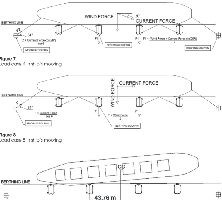
Figure 7 presents Mooring Case 4, which considers the force of the
Figure 4
Load case 2 in ship’s mooring – Coniguration 1
Figure 5
Load case 2 in ship’s mooring – Coniguration 2
Figure 6
wind acting in the cross direction to the ship, in the reverse direc-tion (pushing the dolphins), and the force of the current acting in the direction at 20º gradient with respect to the ship’s longitudinal axis. In this case, the force of the wind and the cross-sectional component of the current (that pushes the dolphins) were divided into 2 (two) mooring dolphins, and the longitudinal component of the current was imposed exclusively on a cable, namely the bow cable, tied to a mooring dolphin.
Figure 8 shows mooring Case 5, considering the wind force acting in the cross direction of the ship, in the reverse direction (pushing the dolphins), divided in 2 (two) bollards, and the force of the cur-rent acting in the longitudinal direction to the ship, imposed on 1 (one) head of a mooring dolphin.
To obtain the berthing forces, a simulation of the ship’s berthing to the dolphins line was used, which served as a basis for calculating the eccentricity coeicient CE used in berthing power calculations, as presented in Figure 9.
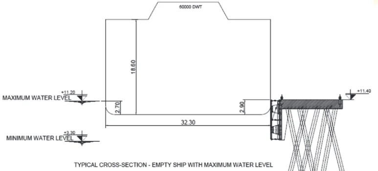
Figure 10 and Figure 11 feature views of the cross sections for critical situations involving the fenders such as an empty ship
with a maximum water level and a loaded ship with a minimum water level.
3.1 Mooring forces
Figures 12 and 13 present the resulting mooring forces for each method studied, by load case and dolphin type. The calculations were performed for two extreme situations, including the maxi-mum and minimaxi-mum water level of the river. The horizontal axis of these igures identiies the mooring case of interest (e.g., Case 1, Case 2, etc.) followed by the identity of the analyzed dolphin, or the mooring and berthing dolphin.
These results represent the force exerted on the mooring cable, considering the horizontal and vertical gradients, with exception of the columns named “Case 4-Mooring” and “Case 5-Berthing”, where the results represent the force applied di-rectly to the berthing dolphin in the opposite direction as that of the forces in the cables, hence why they are represented with a negative sign.
Figure 7
Load case 4 in ship’s mooring
Figure 8
Load case 5 in ship’s mooring
Figure 9
Analyzing Figure 12 and Figure 13, it can be observed that the method of NBR 9782 leads to greater mooring forces in terms of maximum force for each load case, with the greatest force ob-tained for the mooring cable of Case 2, in the Mooring Dolphin under conditions of a minimum water level with an empty ship. The results provided by the method proposed by Mason (1982) were generally very close to the results obtained by the method of the NBR 9782. However, the results obtained by the method of the BS 6349 led to lower values, with the exception of Case 5 for the mooring dolphin in the situation of an empty ship,
be-cause this reference standard did not diferentiate the situations of an empty ship and a loaded ship when calculating the force due to the current.
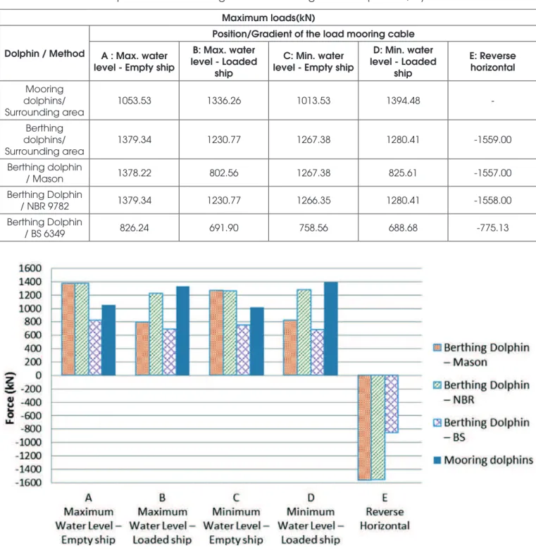
Table 4 and Figure 14 show the results of the maximum loads obtained for each position situation of the specific load stud-ied, for each method, in mooring dolphins, i.e., the greatest force obtained among the five load cases studied for ship mooring, for each position of load action considered (max. wa-ter level with an empty ship, max. wawa-ter level with loaded ship, etc.), and the maximum load obtained by the three methods
Figure 10
Cross section of an empty ship with a maximum water level
Figure 11
for the mooring dolphin. It can be seen that in all cases the results obtained by the method of the BS 6349 were the low-est. The method of NBR 9782 led to higher values for ship’s load situations, followed by the results obtained by the method proposed by Mason (1982). As for the cases of an empty ship and reverse horizontal, the results obtained by the method of the NBR 9782 and that proposed by Mason (1982) were virtu-ally equal.
3.2 Berthing forces
Figure 15 presents the results of the berthing power calculated for each studied method.
To absorb the maximum rated power, a system of fenders of the Taper type was chosen, SCN 1300H - E1.9 (Er = 1023 kN.m; Rr = 1522 kN), and for the maximum increased power, a fender system of the Taper type was chosen, SCN 1400H - E2. 7 (Er = 1554 kN.m; Rr = 2141 kN).
Figure 12
Mooring forces for a maximum water level, by method
Figure 13
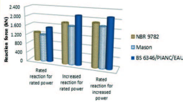
Figure 16 shows the reaction forces resulting from each power calculated for three situations, namely, the Nominal Reaction for Rated Power, Increased Reaction for Rated Power, and Rated Re-action for Increased Power.
Analyzing the results of the berthing forces shown in Figures 15 and 16, the following observations can be noted.
The calculation method of BS 6349 (PIANC/EAU 2004) resulted in a mooring power rated higher than other methods, namely 45.2% higher than the results provided by NBR 9782, and 35% higher than those proposed by Mason (1982), for rated mooring powers. For berthing powers increased by the respective coeicients for each reference, the diferences between the results provided by
BS 6349 and those provided by the NBR 9782 and by Mason (1982) were 55.6% and 44.6%, respectively.
In terms of the reaction forces, considering those arising from the fenders system chosen for this work and its corresponding power diagram, the diferences between the results of the BS 6349 and those of the NBR 9782 and Mason (1982) were 19.0% and 28.2%, respectively, with respect to rated power.
For the reaction due to increased power, the diferences fell to 13.6% with respect to NBR 9782, and 22.0% with respect to Ma-son (1982).
Considering the values obtained in both situations as fol-lows: (i) increased reaction of the coefficient chosen by the
Table 4
Maximum loads on dolphins due to mooring for each cable gradient or position, by method
Maximum loads(kN)
Dolphin / Method
Position/Gradient of the load mooring cable A : Max. water
level - Empty ship
B: Max. water level - Loaded
ship
C: Min. water level - Empty ship
D: Min. water level - Loaded
ship
E: Reverse horizontal
Mooring dolphins/ Surrounding area
1053.53 1336.26 1013.53 1394.48
-Berthing dolphins/ Surrounding area
1379.34 1230.77 1267.38 1280.41 -1559.00
Berthing dolphin
/ Mason 1378.22 802.56 1267.38 825.61 -1557.00
Berthing Dolphin
/ NBR 9782 1379.34 1230.77 1266.35 1280.41 -1558.00
Berthing Dolphin
/ BS 6349 826.24 691.90 758.56 688.68 -775.13
Figure 14
reference, derived from rated berthing power, and (ii) rated reaction arising from the berthing energy increased by the coefficient chosen by the specific reference; it can be seen that the difference between these values when using the BS 6349 method was 0.479%, the NBR 9782 method was 5.263%, and the Mason (1982) method was 5.631%. Keep-ing in mind these resultKeep-ing small differences, we note that it was more interesting to choose the fender that was selected for its increased berthing power, since the safety factor could be guaranteed on the scaling of the fender and also on the design of the maritime facility structure.
It is noteworthy that although the berthing power obtained by the NBR 9782 method was the lowest of the three, the reaction force arising from that power was the second largest, remaining above the value obtained by the method proposed by Mason (1982). This can be attributed to the power diagram of the chosen fender, which led to higher reactions for the power level obtained by the method of the NBR 9782 than for those obtained from the power derived from the method proposed by Mason (1982).
3.3 Mooring Forces and Berthing Power X Ship’s
Deadweight Tonnage
In this section the graphs with information about berthing power and rated mooring forces were calculated according to each method, depending on the ship’s tonnage, for bulk carriers of 5,000 DWT to 250,000 DWT, to allow for a better view of the results obtained for each method. These forces were obtained from the calculation for each ship studied, applied to the same case study of the dolphin’s line.
Figure 17 shows the results of mooring forces obtained in the calculations. The results presented here represent the highest value obtained of the 4 (four) studied combination conditions of the river’s water level and the loading condition of the ship, excluding the results of the case where the ship pushed the dolphin, and keeping in mind that the reaction resulting from berthing exceeded this value.
It can be noted that the method of NBR 9782 led to the best results of the three methods studied, followed by the method
Figure 16
Reaction forces due to berthing, by method
Figure 15
Berthing power calculated by method
Figure 17
proposed by Mason (1982), which provided results on average 11% lower than those of NBR 9782. The method of BS 6349 pro-vided even lower results, which were, on average, 33% lower than those provided by the method of NBR 9782.
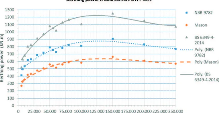
Figure 18 presents the results of rated berthing power calcu-lated for each method, in each ship studied.
For the berthing power, it can be observed that the calculation method of BS 6349 provided better results, which were on av-erage 36% higher than those provided by NBR 9782 and 93% higher than Mason ( 1982).
It is noteworthy that increasing the deadweight tonnage of the ship did not necessarily increase the berthing power, since in-creasing the tonnage of the ship should theoretically reduce the berthing speed up to the limit of 0.08 m/s for ships above 240,000 DWT. This can be seen from the powers obtained for ships above 40,000 DWT.
One reason that may justify the diference obtained between the results provided by the European standards and those pro-vided by the method of NBR 9782 and that of Mason (1982) is the fact that the European standards were updated and have considered the progress in the shipping industry, which has al-lowed, in turn, the building of ships with larger cargo capacities than those existing at the time of the preparation of the Brazilian Standard and Mason’s (1982) study.
t is noteworthy that, in the calculations made to obtain the graph shown in Figure 18, the same parameters were used for all three methods, in order to analyze them without the inluence of a pa -rameters change external to the method such as the approaching speed of the ship. This comment is intended to clarify the difer -ence in the results of the berthing power calculated by the meth-od proposed by Mason (1982), shown in the graph for the ship with 60,000 DWT, from that presented in Figure 15, since for the calculations shown in the above item, the author’s recommen-dations were used for the approaching speed and the reduction coeicient, which led to higher results than those presented here.
4. Conclusions
For mooring forces, we observed a large dispersion in the results of the studied methods. The results obtained in the case study for these types of forces by using the methods of NBR 9782 and Mason (1982) provided results similar to each other. The results obtained by the method of BS 6349 provided results an average of 44% lower than those obtained by other methods, for the case study. In the study of the curve related to mooring forces of X Ship’s DWT, the results obtained according to the method of NBR 9782 were the highest, at an average of 12% higher than those obtained by the method proposed by Mason (1982) and 51% higher than the results provided by the method of BS 6349, which provided the lowest results.
It was deemed necessary to calculate the mooring eforts accord -ing to the 3 (three) reference documents and to choose the high-est results in a more conservative analysis, as the consideration of shape coeicients for wind forces and current may have varied over a range of values, which could produce results up to two times lower. The Brazilian standard NBR 9782 proved to be the most conserva-tive, providing the highest results for the mooring forces and be-ing evaluated as the most appropriate when intendbe-ing to develop a project considering reduced risk of accidents. It was also thought necessary, where possible, to study reduced models to estimate the mooring forces and adjust the resulting shape coeicients.
For berthing forces, it could be seen that the method proposed by the European standards (BS 6349, PIANC, and EAU 2004) led to signiicantly higher values than those proposed by NBR and Mason; the value obtained by NBR method was the small-est of the three in the case study. In the study of the curve Berth-ing Power X Ship’s DWT, the results obtained by the NBR 9782 method were on average 26% lower than those obtained by the European standards, while the results obtained by the method pre-sented by Mason (1982), the diference was 48% on average, in terms of berthing power. It could be concluded that it was more
Figure 18
interesting to choose the fender that was selected for increased berthing power, as a safety factor could be guaranteed on the scal-ing of the fender and also on the design of the maritime facility structure. Thus, it was deemed more appropriate to use European standards for calculating the berthing force and for the scaling of the fenders system, in view of the results obtained and the fact that they are updated standards, i.e., the British standard BS 6349-4 of which the latest version is from 2014.
In terms of internal forces in the structural elements, it was not-ed that although the method of the British Standard BS 6349 led to lower calculated mooring forces, due to the geometry of the dolphins and the direction of the mooring and berth-ing loads, the larger axial compression forces were caused by the reaction coming from the berthing power calculated by the method of BS 6349, and the resulting mooring forces cal-culated by the method of the standard NBR 9782 and by the method presented by Mason (1982) caused the greatest ten-sile stresses on piles, almost equivalent to the forces caused by the reaction coming from the berthing power calculated by the method of BS 6349.
5. Literature references
[1] ABNT (Associação Brasileira de Normas Técnicas). NBR 9782:1987 – Ações em Estruturas Portuárias, Marítimas ou Fluviais. Rio de Janeiro, 1987.
[2] ABNT (Associação Brasileira de Normas Técnicas). NBR 8800:2008 – Projeto de estruturas de aço e de estruturas mistas de aço e concreto de edifícios. Rio de Janeiro, 2008. [3] ABNT (Associação Brasileira de Normas Técnicas). NBR
6118:2014 – Projeto de estruturas de concreto — Procedi-mento. Rio de Janeiro, 2014.
[4] Alfredini, Paolo. Obras e gestão de portos e costas: a téc-nica aliada ao enfoque logístico e ambiental / Paolo Alfredini, Emilia Arasaki – 2ª ed. – São Paulo: Blucher, 2009.
[5] Amador Júnior, Wellington José. Projeto do Píer de um Ter-minal de Contêineres – Estudo de Caso. 2006. 49 f. Trab-alho de Conclusão de Curso – Escola Politécnica, Universi-dade Federal do Rio de Janeiro. Rio de Janeiro, 2006. [6] Amendola, Guilherme Guerra. Projeto Conceitual e Análise
do Estaqueamento de um Píer. 2010. 76 f. Trabalho de Con-clusão de Curso – Escola Politécnica, Universidade Federal do Rio de Janeiro. Rio de Janeiro, 2010.
[7] Blok, J.J.; Brozius, L.H.; Dekker, J.N. The Impact Loads of Ships Colliding With Fixed Structures. In: 15th Annual OTC in Houston, Texas, 1983. Proceedings. Ofshore Technology Conference, 1983. p. 231-240.
[8] British Standard. BS 6349-4:2014 - Maritime structures — Part 4: Code of practice for design of fendering and mooring systems (Reino Unido).
[9] Christan, Priscila de. Estudo da interação solo-estaca su-jeito a carregamento horizontal em ambientes submersos. 2012. 192 f. Dissertação de Mestrado - Programa de Pós-Graduação em Engenharia Civil, Universidade Tecnológica Federal do Paraná - UTFPR. Curitiba, 2012.
[10] CopaboInfra. Catálogo técnico de defensas, 2013.
[11] Costa, Vasco. The berthing ship. The efect of impact on the design of fenders and other structure. The Dock and Harbour Authority, 1964.
[12] Davisson, M. T.; Robinson. K. E. Apud Veloso, Dirceu Alen-car. Fundações, volume 2 : fundações profundas / Dirceu de Alencar Veloso, Francisco de Rezende Lopes. – Nova Ed. – São Paulo : Oicina de Textos, 2010.
[13] Dynamis Techne, Acervo Técnico, 2013.
[14] Fanti. Fábio Dollinger. Concepção, métodos construtivos e dimensionamento de terminais para contêineres. 2007. 171 f. Dissertação de Mestrado – Escola Politécnica da Universi-dade de São Paulo. São Paulo, 2007.
[15] Gaythwaite, John. Design of marine facilities for the berthing, mooring, and repair of vessels / John W. Gaythwaite. – [2nd ed.]. Reston: American Society of Civil Engineers, 2004. [16] Governo Federal. PAC2. Disponível em <http://www.pac.
gov.br/transportes/portos>. Acesso em 03/12/2014.
[17] Huang, Erick T.; Chen, Hamm-Ching. Ship Berthing at a Floating Pier. In: The Thirteenth (2003) International Of -shore and Polar Engineering Conference, 2003, USA. Pro-ceedings. Honolulu, Hawaii, USA, 2003. p. 683-690. [18] Jiang, Chen-wen; Javana, Richard C. An Analytical
Tech-nique for Ship-Fender Interaction. Report of Oice of Naval Research. Arlington, Virginia, 1983.
[19] Leal, Miguel de Mira Godinho Grego. Dimensionamento de Defensas Marítimas. 2011. 151 f. Dissertação de Mestrado – Universidade do Porto, Porto – Portugal, 2011.
[20] Ligteringen, H. Ports and Terminals / H. Ligteringer, H. Vel-sink – 1st ed. – Delf: VSSD, 2012.
[21] Mason, Jayme. Obras portuárias / Jayme Mason. – 2ª ed. – Rio de Janeiro: Campus, 1982.
[22] Natarajan, R.; Ganapathy, C. Analysis of Moorings of a Berthed Ship. In: Marine Structures 8 (1995). p. 481-499. Elsevier Science Limited. ISSN 0951-8339/95.
[23] PIANC - Permanent International Association of Navigation Congresses. Guidelines for the Design of Fender Systems: 2002. Report of Working Group 33 of the Maritime Naviga-tion Commission, 2002.
[24] Pulsar Marine. Catálogo técnico de defensas, 2014. [25] Recommendatios of the Committee for Waterfront Structures
Harbours and Waterways – EAU 2004 (Alemanha), 2004. [26] Revista Infraestrutura Urbana. PINI. Disponível em <http://
www.nfraestruturaurbana.pini.com.br/solucoes-tecnicas/ Transporte/estudo-da-usp-aponta-que-brasil-deve-investir-r-1-327071-1.aspx>. Acesso em 22/09/2014.
[27] Sakakibara, Shigeki; Kubo, Masayoshi. Ship berthing and mooring monitoring system by pneumatic-type fenders. Ocean Engineering 34 (2007) 1174–1181.
[28] Santos, Paulo Rosa; Pinto, Francisco Taveira; Gomes, Fernando Veloso. Experimental evaluation of the tension mooring efect on the response of moored ships. Coastal Engineering 85 (2014) 60–71. Contents lists available at ScienceDirect.
[29] Schellin, T. E.; Östergaard, C. The Vessel in Port: Mooring Problems. Marine Structures 8 (1995) 451-479. Elsevier Sci-ence Limited. ISSN 0951-8339/95.
[30] Sumitomo. Rubber Marine Fenders. Catálogo técnico de de-fensas, 2013.
[31] Thoresen, Carl A. Port designer’s handbook / Carl A. Thore-sen. - [2nd ed.]. – London: Thomas Telford Limited, 2010. [32] Trelleborg Marine Systems. Section 12 – Fender Design.