Finite element model for nonlinear analysis
of reinforced concrete beams and plane frames
Modelo de elementos initos para análise não linear
de vigas e pórticos planos de concreto armado
Abstract
Resumo
In this work, a two-dimensional inite element (FE) model for physical and geometric nonlinear analysis of reinforced concrete beams and plane frames, developed by the authors, is presented. The FE model is based on the Euler-Bernoulli Beam Theory, in which shear deformations are ne-glected. The bar elements have three nodes with a total of seven degrees of freedom. Three Gauss-points are utilized for the element integration, with the element section discretized into layers at each Gauss point (Fiber Model). It is assumed that concrete and reinforcing bars are perfectly bonded, and each section layer is assumed to be under a uniaxial stress-state. Nonlinear constitutive laws are utilized for both concrete and rein -forcing steel layers, and a reined tension-stifening model, developed by the authors, is included. The Total Lagrangean Formulation is adopted for geometric nonlinear consideration and several methods can be utilized to achieve equilibrium convergence of the nonlinear equations. The developed model is implemented into a computer program named ANEST/CA, which is validated by comparison with some tests on RC beams and plane frames, showing an excellent correlation between numerical and experimental results.
Keywords: nonlinear analysis, inite element, reinforced concrete, beams, plane frames.
Neste trabalho apresenta-se um modelo de elementos initos de barra bidimensional, desenvolvido pelas autoras, para análise não linear física e geométrica de vigas e pórticos planos de concreto armado. A formulação do elemento é baseada na teoria de Euler-Bernoulli, em que se desprezam as deformações por cisalhamento. Os elementos de barra possuem três nós e um total de sete graus de liberdade, sendo utilizados três pontos de Gauss para integração do elemento, com a seção transversal discretizada em camadas em cada ponto de Gauss (Método das Lamelas). Admite-se que o concreto e as barras de armadura têm uma aderência perfeita entre si e considera-se que cada camada da seção está submetida a um estado uniaxial de tensões. São utilizadas leis constitutivas não lineares para as camadas de concreto e de armaduras de aço, incluindo-se um modelo reinado de tension-stifening desenvolvido pelas autoras. Adota-se a formulação Lagrangeana Total para conside-ração da não-linearidade geométrica e podem-se utilizar vários métodos para convergência de equilíbrio das equações não lineares. O modelo desenvolvido é implementado em um programa computacional denominado ANEST/CA, o qual é validado em comparação com alguns ensaios de vigas e pórticos planos de concreto armado, observando-se uma ótima correlação entre resultados numéricos e experimentais.
Palavras-chave: análise não linear, elementos initos, concreto armado, vigas, pórticos planos.
a Departamento Acadêmico de Construção Civil, Universidade Tecnológica Federal do Paraná, Curitiba, PR, Brasil; b Departamento de Egenharia Civil, Universidade Federal de Santa Catarina, Florianópolis, SC, Brasil.
Received: 09 Dec 2015 • Accepted: 20 Jun 2016 •Available Online: 17 Apr 2017
1. Introduction
Due to the advance in technology combined with the use of more resistant materials, more complex and slender structures are cur-rently being designed, arising thus the necessity of more elabo-rated computational methods for structural analysis and design. In structural analysis of reinforced concrete (RC) structures, the more reined methods should account for the structure nonlinear behavior, due to material nonlinearities (physical nonlinearity), as well as to changes in the deformed shape of the structure (geometric nonlin-earity). Among the more reined methods, the Finite Element Method (FEM) stands out as one of the most utilized nowadays, which, for the case of plane structures, can be employed by using either bar or plane elements. Yet only a few computer programs are available for nonlinear inite element analysis of RC structures, and their cost is high in comparison with other programs. Due to this fact, reined i-nite element (FE) models have been mostly used by researchers, and many researchers opt in developing their own models and computer programs. Although several nonlinear FE models have already been developed, this is still an advanced topic in the scientiic-technical community, in view of the diiculty on accurately model the reinforced concrete material, due to cracking of concrete, yielding of steel and the interaction between these materials. Hence, the development of models that combine computational eiciency and good accuracy needs to be more and more incentivized (Silva and Matos [1]). In this work, emphasis is given to the bar element model, as it yields a re-duced number of degrees of freedom as compared to plane element models, making viable the analysis of large structures, which is the aim of the research project under way at the Federal University of Santa Catarina (UFSC), with participation of the authors.
The early FE bar models were developed in the 60’s, and were limited to the analysis of small members and small structures, using simpli-ied constitutive models. One of the irst bar models was the one by Giberson [2], which consisted of a linear elastic element connected by nonlinear springs at its ends, in which predeined moment-rotation relations were utilized. Since then the bar models evolved, particularly with the introduction of the Fiber Model (Kaba and Mahin [3]), which subdivides the element section into overlaid concrete and reinforce-ment layers, by considering nonlinear constitutive laws for the ma-terials in each layer. Another important contribution to the evolution of this kind of model was the introduction of an internal node at the element midpoint with only one axial degree of freedom. As demon-strated by Chan [4], the inclusion of this third node allows a proper representation of the element lexural stifness with variation of the neutral axis position, caused by material nonlinearities. Not including this third node imposes a constraint on the element, making it artii-cially stifer. Holzer et al [5] have used this kind of model for physical
and geometric nonlinear analysis of RC beams/columns. Marí [6] has extended this model to a three-dimensional bar element, with a total of thirteen degrees of freedom (six in each external node and one axial degree of freedom in the internal node), by discretizing the element section into ilaments, and by taking into account long term efects caused by creep and shrinkage. In the model two Gauss points are utilized to integrate the stifness matrix and the internal forces vec-tor of the element, with the constitutive matrix being evaluated only at the element midpoint, and by neglecting the tensile contribution of the intact concrete between cracks (tension-stifening). The geometric
nonlinearity is also considered, by means of the Updated Lagrang-ian formulation. More recently Marí [7] has improved this model, by including a tension-stifening model developed by Carreira and Chu [8]. In Brazil, Schulz and Reis [9] have utilized a model similar to the one by Marí [6] to analyze three-dimensional RC frame structures, by considering physical nonlinearity by means of constitutive equations recommended by Design Codes (NBR-6118 and CEB 90), disregard-ing the tension-stifendisregard-ing efect, and by considerdisregard-ing the Total Lagrang-ian formulation for geometric nonlinearity. There is also another kind of FE bar model that uses a formulation in terms of forces instead of displacements, as the model by Taucer, Spacone and Filippou [10]. In Brazil this kind of model was utilized by Teixeira and de Souza [11] in the three-dimensional analysis of a reinforced concrete building, by using a computer program named OpenSees from the University of California in Berkeley. This model was validated by comparison with a model that uses a co-rotational formulation and with the method known as P-delta. The concept of co-rotational formulation, which al-lows that nodes undergo large displacements and rotations, as well as bars display large elongations and curvatures, has been presented by Pimenta [12]. Pimenta and Soler [13] applied this formulation to analyze one RC beam and two RC plane frames, by adopting a com-pressive constitutive law for concrete similar to the one given in NBR-6118, by neglecting the concrete tensile strength, and by considering the steel as an elastic-perfectly plastic material. A similar model, with a co-rotational coordinate system attached to the element, was utilized by Silva and Matos [1]. The authors utilized the Fiber Model and con-sidered the contribution of concrete between cracks by means of the tension-stifening model developed by Vecchio and Collins [14]. Pinto [15] and Carvalho [16] have also utilized a co-rotational formulation for physical and geometric nonlinear analysis of RC structures. Further details on the literature review of FE models for the analysis of RC structures can be consulted in Stramandinoli [17].
points), which allows the use of coarser FE meshes to capture the spread of nonlinearities along the structure. At each Gauss point the element section is discretized into layers, and it is assumed that each layer is under a uniaxial stress-state. The model does not take creep and shrinkage efects into account and it is limited to RC structures with a dominant lexural behavior, where shear deformation is neglected. It should be pointed out that, in those structures where shear efects become important, bar models based on Timoshenko Beam Theory should be used, as for instance the one developed by the authors in Stramandinoli and La Rovere [19], and Stramandinoli [17], or, alterna-tively, plane inite element models, as, for example, the ones developed by d´Avilla [20], should be employed.
The FE model developed by the authors is presented in Section 2, in the following, and the constitutive equations of the materi-als utilized are described in Section 3. The model is implemented into a computer program named ANEST/CA, which is validated in comparison with an analytical model developed by another author for the case of geometric nonlinearity for large displacements, and in comparison with experimental tests on beams, by considering physical nonlinearity only, and on plane frames, by considering both nonlinearities, as presented in Section 4. At the end of the work, in Section 5, a few conclusions are extracted.
2. Finite element model
A nonlinear model based on the Finite Element Method with isopara-metric formulation where the structure is discretized into bar inite ele-ments, is developed. The Euler-Bernoulli assumption, in which shear deformation is disregarded, is adopted.
The bar inite element utilized has three nodes and a total of seven degrees of freedom (Figure [1]). The two external nodes have three degrees of freedom each: two translations (axial and transversal) and one rotation. The internal node at the element midpoint has only one
axial degree of freedom, similar to the one utilized by Chan [16] and by Mari [2]. Upon inclusion of this node, the horizontal displacement ield in the element becomes compatible (see equation 1 ahead, the irst term shows a parabolic variation with x, the horizontal axis, as well
as the second term due to bending, since v(x) varies cubically with x). This allows the axis x to have an arbitrary position, ixed during the
analysis but not necessarily coincident with the line passing by the sec-tion centroids, in such a way that the element stifness can be prop-erly represented upon variation of the neutral axis position, caused by cracking and other material nonlinearities (further details can be found in Stramandinoli [17]).
The numerical integration of the element is performed by means of three Gauss points, and at each point the section is discretized into concrete layers overlaid to longitudinal reinforcement layers (Fiber Model). It is assumed that concrete and reinforcing steel are perfectly bonded, and that each layer is under a uniaxial stress-state. Nonlinear constitutive laws are utilized for the materials, as described in Section 3. Regarding the geometric nonlinearity, the Total Lagrangian Formula-tion, considering moderate rotations, is utilized.
The element formulation is described in the following, by considering initially linear-elastic material, and in the sequence including physical and geometric nonlinearities.
In all equations along the text, bold-faced characters represent either a vector or a matrix.
2.1 Formulation for linear-elastic material
By considering the Euler-Bernoulli Beam Theory, the displacement ield along the element is given by:
(1)
where
u
is the longitudinal displacement,u
0 is the longitudinalFigure 1
Bar element with 3 nodes and 7 degrees of freedom; cartesian coordinates (x,y,z) and natural
displacement along the reference axis x,
v
is the transversal dis-placement andθ
is the rotation of the cross-section.The longitudinal strain and stress in the element are:
(2)
(3)
where
E
is the longitudinal modulus of elasticity of the linear-elastic material.By introducing the natural coordinate
=
x
L
ξ
, the displacementield in terms of nodal displacements can be written as:
(4)
(5)
(6)
(7)
in which:
and where
α
1 is related to the displacement of the internal node,u
3:(8)
and the interpolation functions
N
( )
ξ
are given in the Annex. From the displacement ield, the strain in the element can be determined (see details in the Annex). The strain and stress vectors are given by:and
(9)
where is the nodal displacement vector; is the linear matrix that relates strain to nodal displacements, which is obtained from equations (2) and (4) to (7):
(10)
and is the constitutive matrix for linear-elastic material, in t h e uniaxial case.
By applying the Principle of Virtual Work and after some algebraic manipulations (Stramandinoli [17], Cook [21]), the equation that deines the stifness matrix can be found:
(11)
and also the internal forces vector in the element:
(12)
The integrals in equations (11) and (12) can be obtained by means of numerical integration, and, in this work, the Gauss integration rules with three integration points are utilized.
Next, a static-condensation procedure is applied to condense out the seventh degree-of-freedom in the element stifness ma-trix and in the element force vector, from which the global stif-ness matrix and the global internal forces vector of the structure are assembled.
2.2 Formulation including physical nonlinearity only
In order to include physical nonlinearity, besides the Euler-Bernoulli assumption, it is assumed that: the element undergoes small strain and displacements; concrete and steel are homogeneous materi-als and there is a perfect bond between them; the element cross-section is discretized into layers, by considering that each layer is under a uniaxial stress-state; the tension-stifening efect occurs in the concrete after cracking; the reinforcing steel is an elastic-plastic material with strain-hardening; the total internal forces at each section are obtained upon superposition of the forces derived from the stresses in the concrete layers to those arising from the stresses in the reinforcement layers.
Upon inclusion of physical nonlinearity, equations (11) and (12) need to be modiied, since the stresses and the constitutive matrix
vary along the element, and , therefore an
it-erative procedure becomes necessary to achieve force equilibrium at each load step. Solution of the nonlinear equilibrium equations can be obtained by means of either the Newton-Raphson methods or the Arc-length method (Stramandinoli [17]). Loads are applied incrementally, and for each load step the internal forces vector and the tangent stifness matrix of the element are calculated at each iteration of the iterative procedure:
(13)
where is the secant constitutive matrix of the material.
It can be demonstrated that the tangent stifness matrix is given by (Stramandinoli [2]):
(14)
where is the tangent constitutive matrix of the material. For comparison with the well-known stifness matrix (6 × 6) of a linear-elastic plane frame element, the secant stifness matrix (7 × 7) of the element considering only physical nonlinearity, which contains coupling terms between axial and bending stifness, is presented in the Annex. In the initial elastic stifness matrix, these terms become null for the case that the longitudinal axis x of the
2.3 Formulation including both physical
and geometric nonlinearities
Regarding the geometric nonlinearity, the Total Lagrangian Formu-lation, with the simpliication for moderate rotations, is utilized. By considering moderate rotations, equations (1) remain valid, how-ever the strain becomes:
(15)
This strain can be separated into two parts, a linear one,
ε
L , equivalent to the one given by equation (2), and another one non-linear,ε
NL. Rewriting the strain in matrix notation, it follows:(16)
where:
which is equation (2) presented previously and
(17)
By rewriting equation (6) using matrix notation, it follows:
(18)
and its derivative with relation to x becomes:
where
; .
Equation (17) can then be written in the following way:
(19)
The incremental form of strain is given by:
(20)
By replacing the expressions that deine
ε
L, equation (9), andNL
ε
, equation (19), into the equation (20) above, yields:(21)
or else:
(22)
and where is the matrix that relates strain with displacements (linear), equivalent to equation (10).
For this case, with both nonlinearities considered in the model, the internal forces vector becomes:
(23)
The tangent stifness matrix is still given by the expression:
(24)
But in this case, upon derivation of the terms in equation (24), it leads to:
(25)
Hence, it follows that the tangent stifness matrix is composed of three matrices:
- One matrix obtained considering physical nonlinearity, ex-pressed as:
(26)
- Another matrix, usually deined as geometric matrix, , given by:
(27)
- And one matrix caused by initial displacements by consider-ing the structured deformed, which is given by the addition of three components:
(28)
If instead of the Total Lagrangian Formulation, the Updated La -grangian Formulation were utilized, this last matrix would not enter in the formulation, however it would become necessary to update the coordinates in all steps.
For both this case, in which both nonlinearities are considered, and the case of physical nonlinearity only (section 2.2), the stif-ness matrix and the internal forces vector are obtained by means of numerical integration, using the Gauss Rules with three inte-gration points along the longitudinal axis. At each Gauss point the constitutive matrix and the stress vector are obtained upon addition of values arising from the concrete and from the rein-forcement layers, which in turn are obtained from the nonlinear constitutive equations for uniaxial state, as described in the fol-lowing Section 3.
phenomenon. This nonlinear FE model using bar elements was implemented into a computer program called ANEST/CA, previ-ously named ANALEST (Stramandinoli [17]), developed in FOR-TRAN 90 language.
3. Uniaxial constitutive equations
3.1 Concrete under compression
For concrete subjected to compression, both the modiied Hog-nestad model and the CEB model can be utilized in the ANEST/ CA program, but in this work only the modiied Hognestad model, described in the following, was utilized.
The Hognestad [24] model has already been utilized by several au-thors, showing good results in comparison with experimental tests. In this work this model is modiied, using a parabola to describe the compressive stress-strain curve for both the ascending and the descending branch, after the peak:
(29)
where
cm
f
is the compressive strength of concrete andε
0 is thecor-responding strain.
3.2 Concrete under tension
For concrete under tension, the model proposed by the authors in Stramandinoli and La Rovere [18] is utilized in this work for all examples. In this model, the material is assumed to behave linear-elastically until the tensile strength of concrete is reached, and, beyond cracking, the tension stifening efect, described by the fol-lowing equation, is considered:
(30)
(31)
where:
ct
f
is the tensile strength of concrete andε
cr is the correspond-ing strain;ε
y is the strain value corresponding to yielding of the reinforcement, after which the stressσ
ct drops abruptly to zero;α
is an exponential decay parameter, which is a function of the reinforcement ratio( )
ρ
and of the steel-to-concrete modular ratio( )
n
, deined by the equation:(32)
This equation was derived for bars, where the entire member is subjected to tension, and it was validated by comparison with ex-perimental results from reinforced concrete bars subjected to direct tension, using diferent reinforcement ratios, showing an excellent correlation (Stramandinoli and La Rovere [18]). In order to apply this model to beams, the efective area that corresponds to the
tensile zone in the member section needs to be obtained, which can be estimated using the equation given in the CEB-FIP Model Code 1990 [25]:
(33)
where
h
is the nominal depth of the beam,d
is the efective depth, andx
k
is the neutral axis depth.Recalling that in RC beams under bending, the relationship be-tween nominal and efective depth is usually given by
h d
− ≅
0,1
h
, the efective area can then be expressed, approximately, as:(34)
This approximate equation will be utilized in this work to calculate the reinforcement ratio in all examples of beams and plane frames, by considering the tension-stifening efect only in this efective area. In the numerical analyses where the tension-stifening efect is not considered, the stress drops abruptly to zero in the stress-strain curve, after the tensile strength limit,
f
ct, is reached. It should be noted that the tension-stifening efect is more accentu-ated for smaller values of theα
parameter, which means smaller values of reinforcement ratios, since theα
parameter increases with increasing values ofρ
and/orn
. In order to illustrate this ef-fect and show the inluence of the reinforcement ratio on the tension-stifening model proposed by the authors, a graph of the proposed model upon variation of( )
n
ρ
is shown in Figure 2b, in comparison with other tension-stifening models – the one by Vecchio and Col-lins [14] and the bilinear model from Figueiras [26], both displayed in Figure 2a, which are independent of the reinforcement ratio.3.3 Reinforcing steel
It is assumed that the reinforcing steel, under tension and com-pression, is an elastic-plastic material, modeled by a bilinear stress-strain curve. In order to avoid convergence problems and oscillations in the iterative process, a parabolic curve is itted between the elastic and plastic branches of the bilinear stress-strain curve, between 0.8 and 1.2
ε
y (La Rovere [27]). Strain hardening of the reinforcing steel may or may not be considered, through the use of a coeicientsh
, which is the plastic-to-elastic modular ratio (sh
= 0 for horizontal threshold, perfectly plastic steel). The ultimate strain is calledε
u and the corresponding stress,f
u.4. Comparison of results given by
the proposed model with analytical
and experimental results obtained by
other authors
giving emphasis to structures with dominant lexural behavior. Only one example of plane frame subjected to large displacements was chosen, by considering only geometric nonlinearity, and it will be compared to another analytical model in section 4.3. The other ex-amples – RC beams considering only physical nonlinearity, and RC plane frames considering both nonlinearities, physical and geometric, will be compared to experimental tests.
Regarding the choice of the FE mesh, parametric studies conducted by Stramandinoli [17] in simply-supported beams have shown that, under 4-point bending, in which the central span is subjected to pure bending, the solution obtained using a mesh of 4 elements basi-cally coincided with the one obtained using 24 elements, showing that the model is objective, without mesh dependency. As for the case of beams under a concentrated load applied at mid-span, con-vergence of the solution was obtained for meshes with at least 10 elements. On the other hand, for a plane frame of one span and one story, fully ixed at the base, a certain mesh dependency was observed, though the load-displacement curves were basically coin-cident until the peak, the values of ultimate load and corresponding displacement varied a little by reining the mesh up to 20 elements. The author thus recommends that a iner mesh be utilized for plane frames, but imposing a restraint of not employing elements of length less than its cross-section depth, as recommended by Bazant et al.
[28]. Stramandinoli [17] has also investigated, for several examples, the efect of number of layers used to discretize the element sec-tion, concluding that for 10 layers or higher there was no change in the numerical solution, hence in this work 20 concrete layers were adopted in all examples.
In all numerical analyses, the modiied Hognestad model was utilized for concrete under compression and the Newton-Raphson method was applied for solution of the nonlinear equations, except for the ex-ample in section 4.3, where the Arc-length method was employed. In the examples of beams and frames tested experimentally, the material properties for concrete and steel measured experimental-ly were utilized in the numerical model, whenever available (shown in highlight in Tables 1 and 2), otherwise they were estimated using the values and equations recommended by the Brazilian Code for concrete structures, NBR-6118.
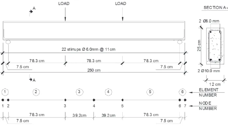
4.1 Simply-supported beams tested by Beber
Among the simply-supported beams tested under 4-point bending by Beber [29], two of them, VT1 and VT2, are initially utilized for comparison with the results generated by ANEST/CA program, considering only physical nonlinearity. The two beams are identical, and their geometry and reinforcement, the applied loading, and the mesh utilized in the inite element analysis are all displayed in Figure 3, with dimensions given in cm. The ma-terial properties are presented in Table 3. In order to demon-strate the importance of the tension-stifening efect, a numeri-cal analysis without considering this efect was also performed. Comparison between numerical and experimental results is pre-sented in Figure 4 in terms of a graph “total applied load versus
vertical displacement at mid-span”. It can be observed that the FE model could capture very well the ascending branch of the experi-mental curve obtained in the experiexperi-mental tests, showing a good
Figure 2
Comparison of tension-stiffening models: (a) Collins and Vecchio [14] and bi-linear model [26]; (b)
approximation even after the onset of cracking when the tension-stifening efect is considered. When such efect is not considered, the numerical model displays a much more lexible behavior than the experimental one, as expected, since this efect is more accen-tuated in beams with low reinforcement ratio. The onset of yield -ing of reinforcement was accurately captured by the numerical model, corresponding to a total applied load of 44 kN. However, beyond that, the post-yielding response of the specimens could not be measured experimentally since the instruments have been re-moved to avoid damage. The ultimate total load measured experi-mentally was 47 kN, while the numerical value obtained at failure by program ANEST/CA was a bit lower, 46 kN.
4.2 Simply-supported beams tested by Juvandes
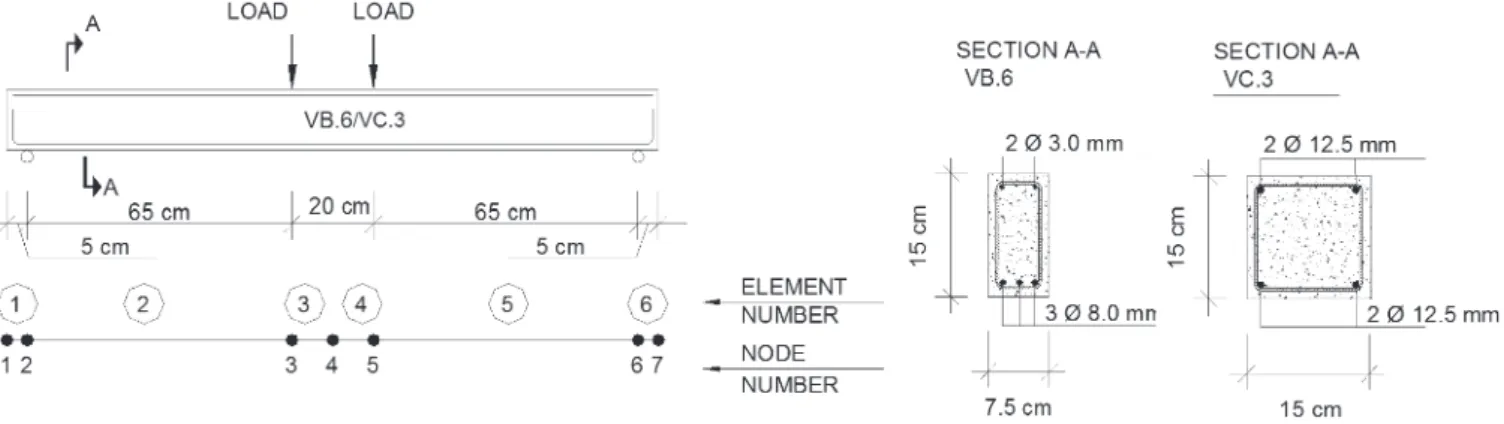
Among the beams tested in the experimental program conduct-ed by Juvandes [30], two simply-supportconduct-ed beams under 4-point bending (VB6 and VC3) were selected to be analyzed with ANEST/ CA program, by considering only the physical nonlinearity. Beam geometry and reinforcement, loading and FE mesh used in the analyses are shown in Figure 5 (dimensions given in cm), while the material properties are given in Table 1. The numerical analyses were performed with and without considering the tension-stifening efect, to illustrate the importance of such efect.
Comparison between numerical and experimental results is presented in terms of “total applied load versus vertical displacement
at mid-span” graphs in Figures 6 and 7. For beam VB6, it can be
observed from Figure 6 an excellent approximation of the numerical model, considering tension-stifening, with respect to the experimental test, with the curve obtained numerically basically coinciding with the one obtained experimentally, in the post-cracking and post-yielding ranges. The numerical model was only a little stifer at the beginning of the elastic range, before the onset of cracking, region more sus-ceptible to instrumentation imprecision, and it predicted very well the ultimate load, with a slightly smaller corresponding displacement. A more lexible behavior of the numerical model is again observed when the tension-stifening efect is not considered in the analysis (NO T.S.). For the other beam, VC3, the numerical model consider-ing tension-stifenconsider-ing reproduced very well the experimental model in the elastic range but, beyond that, for a total load higher than 25 kN, it became slightly stifer than the experimental model (see Fig-ure 7). The numerical model also predicted well the ultimate load, but showed a corresponding displacement smaller as compared to the experiment. For this particular beam VC3, the diferences in the analyses with and without tension-stifening consideration are smaller because, besides its higher reinforcement ratio, the elastic modulus of concrete is low, resulting in a high value for the modu-lar ratio
n
, which consequently results in a high value for theα
parameter (see Table 1); therefore there is less tension-stifening efect as compared to the beams analyzed before.4.3 Plane frame studied by Williams
In order to verify in this work the geometric nonlinearity formulation
Table 1
Material properties used in numerical analysis of beams VT1/VT2/VB6/VC3 (experimental values in bold,
calculated or estimated values without bold)
Table 2
Material properties used in numerical analysis of frames (experimental values in bold, calculated or
estimated values without bold)
Beam
Concrete Tension – stiffening Reinforcing steel
fcm (MPa)
ftm
(MPa) ε0 n ρeff nρeff
α
(5 layers) φ
fy (MPa)
Es
(GPa) sh
VT1 / VT2 33.58 2.62 0.0020 6.39 1.50 % 0.096 0.040 6 mm 738 214.83 0.016
VT1 / VT2 33.58 2.62 0.0020 6.39 1.50 % 0.096 0.040 10 mm 565 214.83 0.000
VB6 37.9 2.90 0.0020 5.15 4.60 % 0.240 0.072 3 mm 192 174 0.001
VB6 37.9 2.90 0.0020 5.15 4.60 % 0.240 0.072 8 mm 497 195 0.0042
VC3 20.7 1.60 0.0020 9.00 3.80 % 0.342 0.093 12.5 mm 507 184.6 0.0014
Frame
Concrete Reinforcing steel
fcm (kN/m2)
ftm
(kN/m2) nρeff
α (5
layers) ε0
fy (kN/m2)
Es
(kN/m2) εu sh
P2 36500 2814 0.464 0.113 0.0023 293000 200000000 0.01 0.01
A40 29096 2303 0.443 0.110 0.002 353000 189791000 0.015 0.029
of the proposed model, and in view of the lack of examples of experi-mental testing on RC structures subjected to large displacements (since such tests are of diicult execution), an example of a plane frame composed of two bars slightly inclined and made of hypotheti-cal material is analyzed. This frame was studied by Williams apud Peterson and Petersson [31], and is referred in several works relat -ed to this topic. The frame geometry is display-ed in Figure 8 and the element properties are: modulus of elasticity E = 70.735 GPa; cross-sectional area A = 1.18 cm²; and moment of inertia I = 0.0374 cm4.
In the numerical analysis the structure was discretized into 20
ele-ments of equal length and the material was assumed to be linear-elastic. Firstly the model was applied using the matrices
k
g andk
u , and secondly just using thek
g matrix. For solving the nonlinear equations, the Arc-length method was utilized, since the structure presents a critical point. Comparison of both numerical analyses with the one obtained from the analytical model used by Petersson and Petersson [31], expressed in terms of a graph - “load versus verticaldisplacement at the center of the frame”, is shown in Figure 9. The model with both matrices
k
g andk
u could capture the entire response of the structure, including the post-critical range, captur-ing also the efect known as snap-through, with the curve obtainedby the numerical model coinciding with the one from the analytical model of Petersson and Petersson [31]. However, when the matrix
u
k
was not included in the formulation, converge problems arose in the analysis close to the response peak, and it was not possible to capture the response for the complete load history. It should be pointed out, however, that, in many examples of RC plane frames, the model with just the geometric matrix,k
g, is suicient to obtain good results (Stramandinoli [17]).4.4 Plane frame tested by Cranston
Cranston, apud Bazant et al. [28], has conducted several
experi-mental testing on RC frames hinged at the base, from which one, P2, was selected here for comparison with ANEST/CA program. Several researches have analyzed this frame; besides Bazant et al. [17], it can be quoted: Lazaro and Richards [32], Sun et al. [33],
and Bratina et al. [34].
Figure 10 shows the frame geometry, the cross-section of the members, the load application points, the supports, and the mesh utilized to discretize the structure (18 elements) in the numerical analysis. The material properties used in the numerical analysis are given in Table 2.
Figure 3
Tested beams (VT1 and VT2) geometry and reinforcement; load application and support positions
(Beber [29])
Figure 4
Figure 11 illustrates the graph of “total load (kN) versus vertical
displacement at mid-span (mm)” for frame P2. From the graph one can realize that the curve obtained using the numerical model basi-cally coincided with the one obtained experimentally until the load peak was reached; the numerical model just showed to be a little stifer in the post-yielding range of the reinforcement. After reaching the peak resistance of the frame, the experimental curve showed a descending branch, efect known as softening. In the numerical
analysis (considering tension stifening), the onset of yielding of the reinforcing steel occurs at mid-span of the horizontal bar for a load P = 15.7 kN, whereas, for P=20.4 kN, yielding of the rebars initiates at the ends of the horizontal bar and also at the top of the columns. Close to the ultimate load (between 22.2 and 22.3 kN), started the convergence problems, and it was not possible to con-tinue the analysis and capture the post-peak branch, by either us-ing the Arc-length method or the Newton-Raphson method under
displacement control. Such convergence problems are commonly found in analyses considering physical nonlinearity when one or more coeicients in the diagonal of the global stifness matrix of the structure are close to zero.
4.5 Plane frames tested by Ernst et al.
Ernst et al. [35] perform a study on the behavior of RC plane frames,
testing several frames hinged at the base, of one span and one story. Among the tested frames, two of them (A40 and A60) were selected for comparison with the numerical model. The frame ge-ometry, the cross-section of the members, and the load application points are displayed in Figure 12. A total of 36 bar elements were used in the structure discretization for the numerical analysis, and the material properties and parameters utilized are shown in Table 2. Figure 13 illustrates the graph of “total load (kN) versus
verti-Figure 5
Tested beams (VB6/VC3) geometry and reinforcement; load application and support positions
(Juvandes [30])
Figure 6
Comparison between numerical (ANEST/CA)
and experimental results for beam VB6 tested by
Juvandes [30]
Figure 7
cal displacement at mid-span (mm)” for frame A40 and Figure 14 for frame A60. It can be observed from both graphs that the numerical model could capture satisfactorily the behavior of the frames observed in the tests. The numerical model showed to be a little stifer since the initial elastic range, and this dif-ference increased a little in the post-cracking range. For both frames, the ultimate load obtained numerically was larger than the one obtained experimentally, and for frame A40 the ultimate displacement was somewhat smaller in comparison with the ex-perimental value.
5. Conclusions
A 2D inite element model, using bar elements with seven degrees of freedom for physical and geometric nonlinear analysis of rein-forced concrete structures, was presented in this work. The model was implemented into a computer program named ANEST/CA and
it was veriied in comparison with analytical and experimental re-sults obtained by other authors.
Regarding the geometric nonlinearity, the model could capture very well the behavior of linear-elastic structures under large displace-ments, by using the formulation with matrices
k
g andk
u. As far as physical nonlinearity is concerned, comparison between the nu-merical model and experimental tests for structures with dominantFigure 8
Load application and support positions for
Williams’ frame (Petersson and Petersson [31])
Figure 9
Comparison between numerical (ANEST/CA) and
analytical results (Petersson e Petersson [31]) for
Williams’ frame
Figure 10
lexural behavior, in terms of load-displacement curves, showed very good agreement for the case of beams and good agreement for the case of plane frames. This work also demonstrated the im-portance of considering the tension-stifening efect, especially in beams. Besides the numerical results presented here, the ANEST/ CA program can also provide other important information in struc-tural analysis, such as the evolution of cracking and of stress in the concrete and in the reinforcement layers, along the load history (Stramandinoli [17]).
When shear efects become important, in the presence of inclined cracks, another model that takes that into consideration should be employed, as, for instance, the bar model developed by Straman-dinoli and La Rovere [19], based on Timoshenko Beam Theory, or, alternatively, plane inite element models using bi-axial constitutive models, as, for example, the ones developed by d´Avilla [20]. The ANEST/CA program was also used for comparison with simpli-ied methods by Junges [36] for the case of beams, by Gelatti [37] for plane frames, and by Junges and La Rovere [38] for the case of continuous beams. The numerical model described here is cur -rently being extended and implemented into ANEST/CA program to allow for the analysis of three-dimensional reinforced concrete structures, by including also the efect of coninement in concrete provided by the stirrups.
6. References
[1] SILVA, R. M.; MATOS, E. F. Análise não-linear de pórticos planos de edifícios altos em concreto armado considerando a contribuição do concreto tracionado. In: Jornadas
Su-damericanas de Ingeniería Estructural, Punta del Este, p. 1-15 Anais CD-ROM, 2000.
[2] GIBERSON, M. F. The response of nonlinear multi-story structures subjected to earthquake excitation. PhD Thesis. 1967. 232 p. California Institute of technology, Pasadena, California, USA, 1967.
[3] KABA, S.; MAHIN, S. A. Reined modeling of reinforced concrete columns for seismic analysis. EERC Report 84-03. Earthquake Engineering Research Center, University of California, Berkeley, USA, 1984.
[4] CHAN E. C. Nonlinear geometric, material and time depen-dent analysis of reinforced concrete shells with edge beams. 1982. 361 p. Ph.D. Dissertation (Structural Engineering and Structural Mechanics). University of California, Berkeley, USA, 1982.
[5] HOLZER, S.M.; SOMERS, A.E.; BRADSHAW, J.C. Finite re-sponse of inelastic RC structures. Journal of the Structural Division (ASCE), v. 105, n. ST1, p. 17-33, 1979.
[6] MARÍ A.R. Nonlinear geometric, material and time depen-dent analysis of three dimensional reinforced and pre-stressed concrete frames. Report, no. UCB/SESM – 84/12.
Department of Civil Engineering, University of California, Berkeley, USA, 1984.
[7] MARÍ A.R. Numerical simulations of the segmental con-struction of three dimensional concrete frames. Engineering Structures, v. 22, p. 585-596, Ed. Elsevier, 2000.
[8] CARREIRA, D. J.; CHU, K.H. Stress-strain relationship for reinforced concrete in tension. ACI Journal, v. 83, n.3, p. 21-28, 1986.
Figure 11
Comparison between numerical (ANEST/CA)
and experimental results for frame P2 tested by
Cranston (apud Bazant et al. [28])
Figure 12
Tested frames (A40/A60) geometry and
reinforcement; load application and support
positions (Ernst et al. [35])
Figure 13
[9] SCHULZ, M.; REIS, F.J.C. Estabilidade das estruturas de concreto para solicitações combinadas. In: V Simpósio EPUSP sobre Estruturas de Concreto. Anais CD-ROM, p. 1-18, São Paulo, 2003.
[10] TAUCER, F.F.; SPACONE, E.; FILIPPOU, F.C. A iber beam-column element for seismic analysis of reinforced concrete structures. EERC Report 91/17 - Earthquake Engineering Re-search Center, University of California, Berkeley, USA, 1991. [11] TEIXEIRA, M. R.; de SOUZA, R.M. Análise não linear física
e geométrica de um edifício de múltiplos andares em con-creto armado utilizando-se a plataforma OpenSees. In: V Simpósio EPUSP sobre Estruturas de Concreto, Anais CD-ROM, p. 1-19, São Paulo, 2003.
[12] PIMENTA, P. M. Análise não linear de pórticos planos. In: Anais EPUSP, v. 1, n. 1a, p. 563-582, São Paulo, 1988. [13] PIMENTA, P.M.; SOLER, J.G.M. Estabilidade de pórticos
pla-nos de concreto armado. In: Anais do Simpósio EPUSP sobre Estruturas de Concreto, 1, v.2., p. 501-527, São Paulo, 1989. [14] VECCHIO, F. J.; COLLINS, M. P. The modiied compression
ield theory for reinforced concrete elements subjected to shear. ACI Journal, v. 83, n. 2, p. 219-231, 1986.
[15] PINTO, R. S. Análise não-linear das estruturas de contra-ventamento de edifícios em concreto armado. 2002. 155 p. Tese (Doutorado) - Curso de Engenharia Civil, Escola de Engenharia de São Carlos - USP, São Carlos, 2002. [16] CARVALHO, M. F. M. S. Formulação corrotacional para
análise de vigas com elementos initos. 2010. 71 p. Disser-tação (Mestrado) - Curso de Engenharia Mecânica, Univer-sidade Nova de Lisboa, Lisboa, 2010.
[17] STRAMANDINOLI, R.S.B. Modelos de elementos initos para análise não linear física e geométrica de vigas e pórti -cos planos de concreto armado. 2007. 189 p. Tese (doutora-do) – Universidade Federal de Santa Catarina, Florianópo-lis, Brasil, 2007.
[18] STRAMANDINOLI, R.S.B. e LA ROVERE, H.L. An Eicient Tension-Stifening Model for Nonlinear Analysis of Rein-forced Concrete Members. Engineering Structures v.30, n.7, p.2069-80, Ed. Elsevier, 2008.
[19] STRAMANDINOLI, R.S.B. e LA ROVERE, H.L. FE model for nonlinear analysis of reinforced concrete beams considering shear deformation. Engineering Structures v. 35 p. 244–253, Ed. Elsevier, 2012.
[20] D’AVILA, V. M. R. Estudo sobre modelos de issuração de peças de concreto armado via método dos elementos ini-tos. 2003. 259 p. Tese (Doutorado) - Universidade Federal do Rio Grande do Sul, Porto Alegre, 2003.
[21] COOK, R. D.; MALKUS, D. S.; PLESHA, M.E. Concepts and Applications of Finite Element Analysis. 3rd. ed. Ed. Jonh
Wi-ley & Sons, Inc., 1989.
[22] RIKS, E. The application of Newton’s method to the prob-lem of elastic stability. Journal of Applied Mechanics, v. 3, p.1060-1065, 1972.
[23] WEMPNER, G. A. Discrete approximation related to non-linear theories of solids. International Journal of Solids and Structures, v. 7, p.1581-1599, 1971.
[24] HOGNESTAD, E. A study of combined bending and ax-ial load in reinforced concrete members. Bulletin Series, 399:128 - University of Illinois, Urbana, USA, 1951. [25] COMITÉ EURO-INTERNATIONAL DU BÉTON. CEB-FIP
Model Code 1990. London, Thomas Telford, 1993.
[26] FIGUEIRAS, J. A. Practical approach for modelling the non-linear response of RC shells. Computational Modeling of Re-inforced Concrete Structures, p. 217-253, 1986.
[27] LA ROVERE, H. L. Nonlinear analysis of reinforced concrete masonry walls under simulated seismic loadings. 1990. 200p. Ph.D. Dissertation (Structural Engineering) - Univer-sity of California, San Diego, USA, 1990.
[28] BAZANT, Z. P.; PAN, J.; CABOT, G. P. Softening in reinforced concrete beams and frames. Journal of Structural Engineer-ing (ASCE), v. 113, n. 12, p. 2333-2347,1987.
[29] BEBER, A. J. Avaliação do desempenho de vigas de con-creto armado reforçadas com lâminas de ibra de carbono. 1999. 108p. Dissertação (Mestrado em Engenharia Civil) – Universidade Federal do Rio Grande do Sul, Porto Alegre, Brasil, 1999.
[30] JUVANDES, L. F. P. Reforço e reabilitação de estruturas de betão usando materiais compósitos de “CFRP”. 1999. 400p. Tese (Doutorado) – Faculdade de Engenharia, Universidade do Porto, Portugal, 1999.
[31] PETERSON, A.; PETERSSON, H. On inite element analysis of geometrically nonlinear problems. Computer Methods in Applied mechanics and Engineering, v. 51, p. 277-286, 1985. [32] LAZARO, A.L. e RICHARDS JR, R. Full-range analysis of concrete frames. Journal of the Structural Division (ASCE), v. 99, n. 8, p. 1761-1783, 1973.
[33] SUN, C. H.; BRADFORD, M. A.; GILBERT, R. I. A reliable numerical method for simulating the post-failure behaviour of concrete frame structures. Computers & Structures, v. 53, n. 3, p. 579-589, 1994.
[34] BRATINA, S.; SAJE, M.; PLANINC, I. On materially and geo -metrically non-linear analysis of reinforced concrete planar
Figura 14
frames. International Journal of Solids and Structures, v. 41, n. 24-25, p. 7181-7207, 2004.
[35] ERNST, G. C., et al.. Basic reinforced concrete frame
perfor-mance under vertical and lateral loads. ACI Journal, v. 70, n. 4, p. 261-269, 1973.
[36] JUNGES, E. Estudo comparativo entre métodos simpliica-dos e modelos de elementos initos não lineares para o cál-culo de lecha imediata em vigas de concreto armado. 2011. 360p. Dissertação (Mestrado) – Universidade Federal de Santa Catarina, Florianópolis, Brasil, 2011.
[37] GELATTI, F. Análise não linear física e geométrica de pórti-cos planos de concreto armado: modelagem por elementos initos de barra. 2012. 226p. Dissertação (Mestrado) – Uni-versidade Federal de Santa Catarina, Florianópolis, Brasil, 2012.
[38] JUNGES, E.; LA ROVERE, H. L. Comparison between sim-pliied and FE models for short-term delection in continu-ous RC beams. Ibracon Structures and Materials Journal, Volume 10, Number 2 (April 2017), p. 315 - 450.
7. Annex
The interpolation functions
N
( )
ξ
, as used in section 2.1, are given by:From the displacement ield, the strain in the element can be deter-mined, by considering equation (2):
where:
and:
in which: and is the curvature.
Hence the curvature can be written as follows:
And thus equation (2) can be rewritten as:
��= 1 −�
��0
�� �
or: