This paper examines the structural design aspects related to vibrations on loors of urban buildings, induced by human activities that can motivate some discomfort for the users thereof. It presents the Brazilian normative regulations concerning human comfort in structures in the presence of vibrations induced by the users in their daily activities, like walking in places such as houses or ofices, and aerobic activities such as dancing, jumping and running. The paper concludes by offering relevant and eminently practical information ready to be used manually or with minimal computer resources by the professionals involved, allowing for veriication in the initial design phase regarding the eventual need of careful verii-cations in the structural design of loors subject to vibrations due to human activities.
Keywords: vibrations on loors, human comfort, normative aspects.
Este trabalho examina a veriicação estrutural referente às vibrações em pisos de edifícios urbanos induzidas pelas atividades humanas que possam motivar algum sentimento de desconforto aos usuários. Apresenta as recomendações normativas vigentes no país relativas ao con -forto humano em estruturas na presença de vibrações induzidas pelo próprio usuário em suas atividades cotidianas tais como a prática do caminhar em ambientes residenciais ou comerciais e de atividades aeróbicas em ambientes diversos, como dançar, saltar e correr. Finaliza oferecendo informações relevantes e eminentemente práticas, possíveis de serem exercitadas manualmente ou com o mínimo de recursos computacionais pelos proissionais envolvidos, permitindo veriicar na fase inicial de projeto a eventual necessidade de maiores cuidados no dimensionamento estrutural de pisos sujeitos as vibrações devidas às atividades humanas.
Palavras-chave: vibrações em pavimentos, conforto humano, aspectos normativos.
Vibrations due to walking and aerobics activities:
a theoretical veriication
Vibrações devidas ao caminhar e às atividades
aeróbicas: uma veriicação teórica
L. A. PRETTI a [email protected]
W. G. FERREIRA a [email protected] A. F. G. CALENZANI a [email protected]
a Centro Tecnológico, Universidade Federal do Espírito Santo, Vitória, ES, Brasil.
Received: 11 Nov 2013 • Accepted: 19 Feb 2014 • Available Online: 03 Apr 2014
Abstract
1. Introduction
Examining the Brazilian Standards relating to the development of designs for reinforced concrete structures (ABNT NBR 6118:2007) as well as steel or composite steel/concrete structures (ABNT NBR 8800:2008), one can see that these standards do not speciically address the issue of vibrations in such structures, in reference to veriication procedures for obtaining responses due to the dynamic loads induced by activities of human occupation.
Below is an excerpt of the content of each one of these standards regarding the recommended treatment for analysis of vibrations on loors due to the activities performed by the users thereof, followed by considerations compared with ISO 2631:1997/2003, with the ex-empliication of a numerical application, with an evaluation and con -clusion as to the validity of the theoretical proposal presented herein.
2. The approach under the brazilian
standards
2.1 ABNT NBR 6118-2007 – design of concrete
structures – procedure
This standard, in items 3.2.8 and 11.4.2.3, deines the limit state for excessive vibrations as that which occurs when “the structure, because of its conditions of usage, is subject to shocks or vibra-tions, the respective effects must be considered in determining the demands and possibility of fatigue must be considered in the design of the structural elements,” then refers to section 23 of the
same standard.
Later on, in section 13.3, paragraph a, it again refers to vibrations
and refers to section 23 as well, but showing – in this item – the data partially transcribed in Table 2.1 of this article, i.e., the effect of vibra -tions due to accidental loads on the sensory acceptance of users. In section 23, speciically in item 23.3 - Limit state of excessive vibration, ABNT NBR 6118:2007 recommends that the analyses relating to vibrations in concrete structures should be done in a lin-ear regime with the natural frequencies fnatbeing kept distant from
the structure’s critical frequency fcrit; this is a function of the use for
which the building is intended, specifying a minimum limit fnat > 1.2 fcrit, as recommended in Table 2.2.
To control these vibrations, it is suggested that the behavior of the structure should be changed by modifying certain factors, including the dynamic actions of excitation or the natural frequency of the structure with the change of the structure’s rigidity or mass, or the damping characteristics.
Otherwise, the analysis is redirected to international standards in
cases where the dynamic analysis requires more speciic precau-tions, at the discretion of the analyst. (ABNT NBR 6118:2007)
2.2 ABNT NBR 8800:2008 – design and execution
of steel and composite steel/concrete
structures for buildings – procedure
This standard, in section 11 – Vibrations, speciically in item 11.4.1, explicitly refers to vibrations by recommending that “Floor systems subject to vibrations, such as those of large areas that have no
partitions or other damping elements, must be veriied in order to
avoid the appearance of unacceptable transient vibrations due to people walking or other sources, according to Annex L.”
Annex L of ABNT NBR 8800:2008, includes general introductory comments and refers to item 4.7.7.3.3: “- Frequent combinations of service,” which deines that “frequent combinations are those that repeat often during the lifetime of the structure, on the order of 105
in 50 years, or that have a total duration equal to a non-trivial part of the period, on the order of 5%.”
And these combinations may be used for reversible limit states, i.e. those that do not cause permanent damage to the structure or oth-er components of the building, including those related to the usoth-er comfort. It concludes by recommending that the natural frequency of the loor structure must never be less than 3 Hz.”
Below, we present general procedures that should be considered for what this standard admits as an accurate assessment. These are transcribed as follows; it states that in the case of vibrations on loors, at least the criteria transcribed below shall be considered in a dynamic analysis:
a) the characteristics and the nature of the dynamic excitations,
Table 2.1 – Limits for deflections
Type of effect
Reason for
the limitation
Example
Displacement
to consider
deflection
Threshold
Sensory
acceptability
Visual
Other
Total
Due to live loads
l/250
l/350
Visible displacements
in structural elements
Vibrations felt on floor
Source: ABNT NBR 6118:2007Table 2.2 – Critical frequency for some specific
cases of structures subjected to
vibrations by the action of people
Case
f (Hz)
critSports gymnasium
Dance or concert halls without fixed seats
Offices
Concert halls with fixed seats
Walkways for pedestrian or bicycles
8.0
7.0
3.0–4.0
such as (for example) those arising from people walking and rhythmic activities;
b) the acceptance criteria for human comfort as a function of the
use and occupation of the areas of the loor;
c) the natural frequency of the loor structure;
d) the modal damping ratio; e) the effective weights of the loor;
Finally, texts of international origin that may be of interest in this analysis are recommended, more precisely, in Annex S-4 thereof. (ABNT NBR 8800:2008)
3. The international approach
3.1 Standards ISO 2631-1:1997 and 2631-2:2003
International standard ISO 2631:1997/2003, consulted in order to support arguments of this technical article, deines the various methods applicable to the measurement of periodic, random and transient vibrations that may be observed in the human body in standardized positions such as standing, sitting and lying. In thisFigure 3.1 – Barycentric axes of the human body
Source: ISO 2631-1:1997
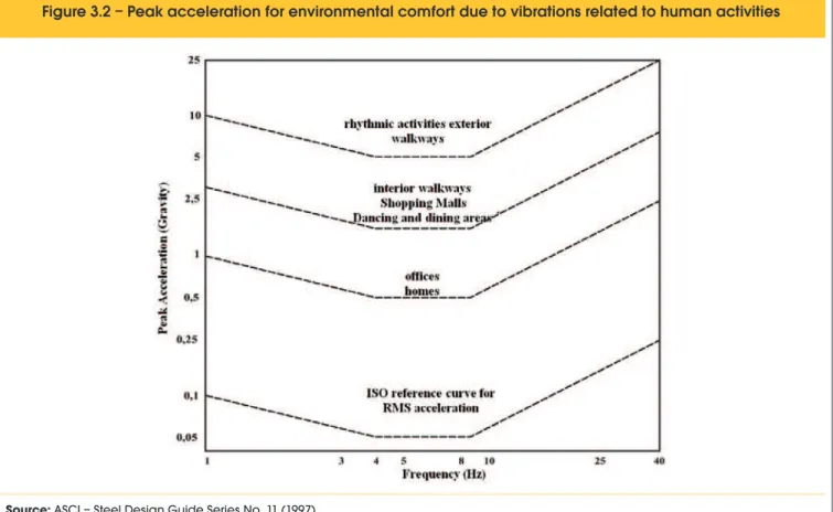
Figure 3.2 – Peak acceleration for environmental comfort due to vibrations related to human activities
situation, this standard addresses the key factors that in combined form can determine the level of exposure to vibrations acceptable by man.
Figure 3.1 shows the principal axes recommended for measur-ing the effects of vibration, in accordance with the plan of entry in the human body according to the position of interest admitted for analysis, according to that speciic standard.
This standard recommends that measurements be taken during a period of time that is suficient and necessary to ensure reasonable statistical accuracy, without any restriction on the duration thereof. (ISO 2631-1:1997, ISO 2631-2:2003)
Possibly, in occurrence of measurements in different periods with clear differences in characteristics there between, sepa -rate analyses should be made for each period and these facts must be reported; likewise it is essential that other factors be recorded, such as age, gender, size, physical capability, etc., of the users.
Moreover, the AISC (“American Institute of Steel Construction”) considers the abacus of Figure 3.2 with peak acceleration rates related to gravitational acceleration, whereby the various types of possible use for the loors are categorized with regard to vibrations due to human activities. (MURRAY et alii, 2003)
The areas of the abacus shown in Figure 3.2 located below the dashed lines correspond to the maximum acceptable limits for peak accelerations corresponding to the respective existing de -scriptions thereof, for the respective natural frequencies.
4. Aspects of the analysis
Brazilian standards ABNT NBR 6118:2007 and ABNT NBR 8800:2008 do not address the merits of theoretical formulations to develop dynamic analysis of problems involving structural vibra-tions, whatever their origin, leaving the suggestion that the design engineer research the topic in the relevant literature.
It is known that in order to ind the response in the ield of the dy -namic analysis of structure, the analyses can be performed both in the time domain and in the frequency domain. Dynamic analysis in the time domain is more suitable in structural projects, considering that all work is carried out only with the resources of mathematics of real numbers, while analysis in the frequency domain makes use of complex numbers, with no practical meaning for the engi -neer. (FERREIRA, W.G, 2002)
5. The theoretical sequence of calculation
5.1 Initial considerations
Manual veriication of the dynamic conditions of a particular loor slab begins by examining the physical characteristics thereof in or -der to better adapt it to a representative structural model regarding the aspect of the structural analysis.
The methodology shown below is based on the recommendations of the AISC (“American Institute of Steel Construction”) compiled from several published articles, and on Brazilian standards ABNT NBR 6118:2007 and ABNT NBR 8800:2008.
5.1.1 Unidirectional loor slab
In this case, the vibrations occur in a single direction of the loor, and the structural model can be conceived as a system supported in just one direction with secondary beams in steel hot rolled sec -tions or joists. This case applies most frequently to walkway de-signs intended for pedestrian trafic. They are designed with a loor slabs normally supported on longitudinal girders supported at the ends, as shown in Figure 5-1b.
5.1.2 Bi-directional loor slab
In this case, the vibrations occur in two directions of the loor, and the structural model is designed as a loor system supported in both directions, as shown in Figure 5.1a and supported by one of the following alternatives:
n On secondary beams n On secondary joists n On primary girders n On primary joists
n On rigid walls in the primary direction
This solution is regularly found in loor designs in multi-story build-ings intended for residential and/or business activity subject to movement of people, such as walking, jumping, and dancing. De-pending on the purpose of their use, they are designed with a slab normally supported on transversal secondary girders, and these in turn are supported at their ends on the primary girders or longitu -dinal rigid walls. Figure 5.1 shows two basic models for analysis.
Figura 5.1 – Modelos típicos para o projeto de pisos de edificações
Fonte: PRETTI (2012)
Piso bidirecional apoiado sobre vigas mistas Piso unidirecional apoiado sobre vigas mistas – (Passarela)
5.2 Structural model
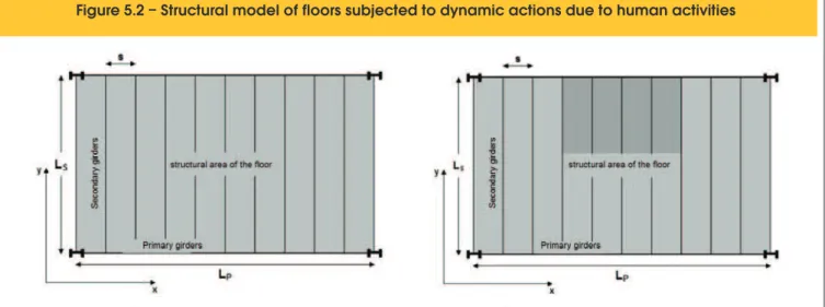
The loor slab examined in this article is speciied in the building plan as shown in Figure 5.2, where one can identify the various parts that comprise the model. In the model are listed the Carte-sian axes according to the directions of the secondary and primary support girders and the spacing between the secondary girders. The dimensions to be considered in this loor slab structural model are as follows:
Direction x – Main dimension LP [m] Spacing between girders
s
[m]Direction y – Secondary dimension LS [m]
5.3 Preliminary calculation and speciications
5.3.1 Effective height of loor slab
Solid slab
Slab thickness de [m] Ribbed slab
Slab thickness dm [m] Rib height dn [m]
Effective height dl =dm+dn [m] Average thickness dn2
m d e
d = + [m]
Center of gravity of the slab
y
CG [mm]5.3.2 Steel beams
Primary direction (x)
Area of cross-section Ax [mm2]
Inertia in relation to the x-x axis
I
x
[mm4]Nominal height of the girder dx [mm] Secondary direction (y)
Area of cross-section Ay [mm2]
Inertia in relation to the x-x axis Iy [mm4]
Nominal height of beams or joists dy [mm]
5.3.3 Modulus of elasticity of the materials
Modulus of elasticity of the concrete Ec [kN/m2] Modulus of elasticity of the steel Ea [kN/m2]
5.3.4 Dynamic modular ratio for obtaining the secondary section
The modular ratio is a proportion established between the modulus of elasticity of the concrete in relation to the modulus of elasticity of the steel, for the purposes of homogenization of the materials and obtainment of the equivalent composite section transformed into a single material, used in the various calculations. In this study, the sections are homogenized in relation to the steel and modular ratio is given as:
(5.1)
ca
E
E
n
35
1
,
=
Where 1,35 Ec refers to the dynamic modulus of elasticity of the
concrete. (MURRAY et alii, 2003)
5.3.5 Service loads per unit of loor area
The loads normally acting on loors can be classiied as follows. In the event that other loads occur, they must also be considered. Dead loads
Weight of the loor slab g1 [kN/m 2]
Weight of the incorporated form g2 [kN/m 2]
Weight of inishing material below the loor slab g3 [kN/m 2]
Weight of inishing material above the loor slab g4 kN/m 2]
Figure 5.2 – Structural model of floors subjected to dynamic actions due to human activities
Source: PRETTI and FERREIRA (2012)
Weight walls on the loor slab g5 [kN/m 2]
Weight of secondary beam per linear meter g6 [kN/m]
Weight of primary girder per linear meter g7 [kN/m]
Weight of people on the loor area g8 [kN/m 2]
Live loads
Weight of people on the loor area q1 [kN/m 2]
Weight of furniture on the loor area q2 [kN/m 2]
Weight of partitions on the loor area q3 [kN/m 2]
5.4 Analysis of the loor regarding secondary direction
Under this analysis criterion, the calculations will be developed irst by favoring the veriication with regard to the secondary direction of the loor, then by focusing on the primary direction, and inally consolidating them into a single step called consoli -dated calculations.
5.4.1 Effective beam panel width of the secondary section
(5.2)
s
Lcolab =
5.4.2 Transformed moment of inertia of the secondary section per unit of width of the loor slab
(5.3)
n
d
D
eLS
12
3
=
In this expression the term
d
e when the slab is solid, equals the effective height of the slabd
l and when it is ribbed, equals the average thickness thereof, as deined in item 5.4.1.5.4.3 Mode of vibration of the panel in the direction of the secondary girders
For the purpose of manual veriication on a slab loor regarding the dynamic load due to the action of people moving about on the loor, as characterized in item 5.3, in situations due to walking, only the lowest modes are of interest. Similarly in other situations such as those due to dynamic loads of the same origin, but with other characteristics, such as those due to aerobic activities like jump-ing, dancjump-ing, and physical exercise it is also suficient to check only the occurrences corresponding to the irst, second and third modes of vibration. (MURRAY et alii, 2003)
5.4.4 Position of the neutral axis in the secondary direction
In this script for manually calculating the position of the neutral axis of the secondary section obtained is referenced to the under-side of the slab when the loor is ribbed and the underunder-side face of the slab when it is solid. In both cases, the slab is supported on the secondary steel beams. For cases in which the loor is a ribbed slab or steel–concrete composite, the expression to be used is the following:
(5.4)
k Colab y m m Colab CG n y d L A d d n L y d A y øø ö çè æ + ÷ø ö çè æ ÷ø ö çè æ -+ = 0 2 ) ( . secFor cases in which the loor slab is solid, the expression to be used is the following:
(5.5)
m Colab y m m Colab CG y d L A d d n L y A y ÷ø ö çè æ + ÷ ø ö ç è æ ÷ ø ö ç è æ -= 2 2 . secExpression 5.5 is a particular case of the previous expres-sion 5.4, when the ribbing is nullified. Note that the calcu -lated value is positive when the position of the neutral axis is above the adopted reference, in this case, the underside of the slab, if ribbed or steel–concrete composite. The under-side is also used when the slab is solid. Otherwise, it will be negative, and the signal should be considered algebraically in the calculations.
5.4.5 Transformed moment of inertia
I
s of the secondary sectionThis transformed moment of inertia of the secondary section of the loor, or compound moment of inertia, is calculated by expression 5.6, where all of the terms have been deined previously. This re-fers to the moment of inertia of a section comprised of a beam and the effective part of the loor slab transformed into a single mate-rial, here steel is adopted.
(5.6)
2
sec 3
2
12
+
çè
æ
÷ø
ö
çè
æ
+
÷ø
ö
ú
ú
ú
ú
û
ù
ê
ê
ê
ê
ë
é
÷ø
ö
çè
æ
m m colab m colabd
y
d
n
L
d
n
L
(
)
2sec
+
-+
+
+
=
y y n CG aTS
I
A
d
y
h
y
I
At this stage of the calculation script, it is necessary to consider the type of beams that are speciied for the secondary direction of the loor. Two cases can occur:
n Case 1 – Steel secondary joists n Case 2 – Steel secondary beams
In case 1, where these elements are joists simply supported on the upper langes of the border girders in the primary direction, ad-ditional considerations must be admitted in order to determine the actual transformed moment of inertia in the secondary direction. In this case, the actual moment of inertia is given by the following expression:
(5.7)
TS chords EffetI
I
I
1
1
+
In this expression the term
γ
is calculated as follows:(5.8)
1 1
-= g
T
C
In order to determine the term
C
T it is necessary to evaluate the ratio LSd whereS
L is the span of the secondary direction and
d
is the height of the supporting joists of the loor slab in the same direction, as a function of the sections of the materials of the lang -es of the top chords of joists.
Hypothesis 1:
In joist formed by chords comprised of single or double angles, the term
C
T is calculated by the expression;(5.9)
8, 2 28 , 0
1
90
,
0
÷÷ø
ö
ççè
æ
-=
- çèæLd÷øöT
S
e
C
for
6
£
L
Sd
£
24
Hypothesis 2:
The joist being formed by the chords comprised of single round steel bars, the term
C
T is calculated by the expression;(5.10)
for
÷ ø ö ç è æ +
= L d
CT 0,721 0,00725 S 10£ £24
d LS
If these steel sections have a solid web, welded web or web bolted directly to the webs of the primary girders of the loor, this trans-formed moment of inertia is considered to be the actual trans -formed moment of inertia with no need for additional calculations as in expression 5.7. In this case, term
C
T=
1
.5.4.6 Loads acting on the compound secondary sections
Based on Brazilian standard ABNT NBR 6118:2007, the combina -tion of active loads to be considered in the calcula-tions is obtained with the direct application of expression 5.11, where it is admitted that such loads have the character of frequent actuation. Loads with this characteristic are those who behave according to the nor -mative deinition stated in section 2.2 above. The primary variable action
F
q1 is taken with its frequent valueΨ
1F
qk,
1 and all other variables actions are taken with their quasi-permanent valuesΨ
2F
qk. Under these conditions, the combination of loads for verify -ing the limit state regard-ing excessive vibrations recommended by ABNT NBR 6118:2007 and ABNT NBR 8800:2008 is as follows:(5.11)
(
)
å
å
=
=
+
+
=
nj j qk j
qk m
i gki
serv
d
F
F
F
F
2 2, ,
1 ,
1 , 1
,
y
y
5.4.7 Delection due to static load in the middle of the secondary span
The deformation due to the static load in the secondary direction
corresponding to the homogenized section in the direction of the Cartesian axis,
y
, in Figure 5.2, is calculated for the condition in which the supports are given by the following expression:(5.12)
Effet a
S serv s S
=
384
5
.
F
E
,I
L
D
5.4.8 Natural frequency in the secondary direction
It is appropriate that the natural frequency in the secondary direction is calculated and specified, given that it may assist in the event that it is necessary to make some ad-hoc changes to the parts of the structure in order to attain a favorable end result regarding the aspect of verification of vibration. The cal -culation is also recommended because the verification as to vibrations in the manner structured in this study is linear with the assumption of superposition of the applied actions. This intermediate verification allows the proposed structural system to be verified at this moment with regard to the provi-sions of items 23.1 of standard ABNT NBR 6118:2007, L.1.2 and L.3.3 of standard ABNT NBR 8800:2008. Standard ABNT NBR 6118:2007 states that fnat >1,2fcrit , where the critical or
excitation frequency is obtained in Table 5.1, and one should also consider that ABNT NBR 8800:2008 recommends that the natural frequency should always be above 3 Hz. It is appropri-ate that these regulatory limits be met simultaneously. Thus, the natural frequency in the secondary direction is cal-culated by:
(5.13)
S
natSec
g
f
D
=
0
,
18
In the event that this natural frequency does not meet the regula-tory recommendation at this stage, the modeled structural system can be revised, whether in the section of the girders, or in the sec-tion of loor slab, or both, according to the interest and possibility allowed by design speciications, thereby adapting it.
Table 5.1 – Critical frequency for some specific
cases of structures subjected to
vibrations by the action of people
Case
f (Hz)
critSports gymnasium
Dance or concert halls without fixed seats
Offices
Concert halls with fixed seats
Walkways for pedestrian or bicycles
8.0
7.0
3.0–4.0
5.4.9 Transformed moment of inertia of the secondary section per girder
This is given by:
(5.14)
s
I
D
EffetS
=
Where
s
refers to the distances between the secondary loor gird -ers, as deined in Figure 5.2.5.4.10 Load acting on the secondary section
The calculation of the applied load on the secondary direction (direc-tion y) of the structural model of Figure 5.2 is done by the expression:
(5.15)
S S serv d
S
s
B
L
F
k
W
=
ççè
æ
,÷÷ø
ö
In this expression, the constant
k
takes on different values according to the border condition of the loor slab, specifyingk
=
1
,
0
when the slab is simply supported in the secondary direction (in the case of secondary joists supported on the upper table) andk
=
1
,
5
when dealing with a continuous slab, in the direction examined (in the case of steel beams welded or bolted onto the webs of the primary girders of the loor). In expression 5.15, the term Bs corresponding to the effective width calculation of the loor in secondary direction is given by:(5.16)
S VS LS S
S
C
D
D
L
B
4 1÷÷ø
ö
ççè
æ
=
B
SL
S3
2
£
The value of BS adopted will be the lower of the values obtained in expressions 5.16. The irst expression only the term CS is still unknown, being arbitrated as a function of the position of the loor on the story, as follows:
1
= S
C , when dealing with a loor at the edge of the story.
2
= S
C , for all other cases.
5.5 Analysis of the loor in the primary direction
In this section, the calculations relating to the dynamic veriication of the loor will be shown, according to the primary direction thereof.
5.5.1 Effective beam panel width of the primary section
The effective beam panel width of the slab
L
Colab in the direction of the primary girders is determined as follows:(5.17)
S Colab
L
L
=
0
,
4
if
0
,
4
L
P<
L
Sor
2
S ColabL
L
=
if
0
,
4
L
P>
L
S5.5.2 Position of the neutral axis of the primary section
The position of the neutral axis of the composite section formed by the girder and supported slab is given by the following expression:
(5.18)
÷ ø ö ç è æ + ÷ ø ö ç è æ + ÷ ø ö ç è æ + ÷ ø ö ç è æ -÷ ø ö ç èæ + +
= 2 2 2 n m ColabP P n m ColabP CG apoio n P P d d n L A d d n L y h d A y prin
The calculated value is positive when the position of the neutral axis is below the reference adopted, in this case, the underside of the slab of the ribbed slab and concrete–steel composite and the underside of the solid slab. Otherwise it will be negative.
5.5.3 Transformed moment of inertia ITP of the primary section
The transformed moment of inertia of the section in the primary direction of the structural system, therefore, is determined through the following expression:
(5.19)
( )
( )
Pr( )
2 32
12
úû
ù
êë
é
+
÷
ø
ö
ç
è
æ
+
ï
ï
þ
ïï
ý
ü
ï
ï
î
ïï
í
ì
úû
ù
êë
é
e in LN e Colab e Colabd
y
d
n
L
d
n
L
. .2
÷
ø
+
ö
ç
è
æ
+
+
+
+
=
n apoio CGP LNP PP
TP
I
A
d
h
y
y
I
When the secondary girders are joists and simply supported on the primary girders, the reduced rigidity on the primary girders must be considered due to the lexibility that occurs in these supports. Hence, the transformed moment of inertia is calculated through the following expression:
(5.20)
(
)
4
P TP P dTP
I
I
I
I
Re=
+
-5.5.4 Loads acting on the compound primary sections
The loads acting on the slab and secondary girders are transferred to the primary girders through the following expression:
(5.21)
4.
,
L
.
F
L
g
F
Colab Serv d S Pd
÷÷
+
ø
ö
çç
è
æ
=
5.5.5 Delection due to the static load in the middle of the primary span
corresponding to the homogenized section in the direction of the Cartesian axis,
x
, in Figure 5.2, is calculated for the condition in which the supports are girders and admitted as being free from the action of the bending moments. This delection is given by the following expression:(5.22)
d TP a
P P d
P EF I L
Re , , 384
5 = D
Note that the load used
F
d,P in expression 5.22 for obtaining thedelection at the center of the primary girders is the nominal load, i.e., is not increased by weighting coeficients, as recommended by Brazilian standards. It is also important to note that the term
I
TP.Red corresponding to the reduced moment of inertia will only oc-cur when the secondary girders are simply supported on the pri -mary girders as occurs with joists. If this type of bond does not occur, this term is replaced by the transformed moment of inertiaI
TP calculated by expression 5.19.5.5.6 Natural frequency in the primary direction
Like the calculation of the natural frequency in the secondary direc-tion, at this instant it is also appropriate that the natural frequency in the primary direction of the system being analyzed should be calculated and speciied, although not of interest to the inal verii -cation of the loor regarding the aspect of the vibrations. Moreover, this speciication, at this stage of the analysis, is recommended be -cause the veriication regarding vibrations in the manner structured in this study is linear, as previously stated.
This intermediate veriication allows for the determination in this phase of analysis as to whether the structural system in the pri -mary direction meets item 23 of ABNT NBR 6118:2003, in which the ratio fnat>1,2fcrit must be observed, according to the purpose of usage speciied in Table 5.1 shown previously.
(5.23)
Pin
nat g
f
D
=0,18
Pr
In the event that this natural frequency does not meet the pro -visions of the standards, the structural system modeled may be revised by changing the section of the primary girders or section of the loor slab, or both, according to interest and design possibility, adapting it to the regulatory recommendation.
5.5.7 Transformed moment of inertia per unit of length in the primary direction
The transformed moment of inertia of the slab in the primary direc-tion DP is calculated as follows:
(5.24)
S TP P IL D =
5.5.8 Effective width of the loor in the primary direction
The calculation width of the loor slab in the primary direction to be adopted
B
P is calculated as follows:(5.25)
S P S P
P L
D D C
B 4
1
÷÷ø ö ççè æ =
In this expression, the term CP is a function of the conditions for binding of the secondary girders on the primary girders, assuming the value 1.60 when the secondary girders are supported on the langes of the primary girders as, for example, when there is the speciication of the joists in the secondary direction. When the secondary girders are connected di -rectly to the webs of the primary girders as occurs, for example, when the speciication of solid-web steel girders, the term CP takes the value 1.80.
5.5.9 Total load per unit of length of the primary section
The portion of the total load per unit of length
W
p in the primarydirection is given by the expression:
(5.26)
PP S
P d P FL B L
W = ,
All terms of expression 5.26 were previously deined and are known from the speciications in items 5.3 and 5.5.4 except
B
P,corresponding to the calculation width of the loor, to be considered according to the following conditions:
(5.27)
P P S P
P C DD L
B
4 / 1 ÷÷ø ö ççè æ
=
when
P S PS
P L L
D D C
3 2 4 / 1
£ ÷÷ø ö ççè æ
S
P L
B
3 2
=
if
P S PS
P L L
D D C
3 2 4 / 1
> ÷÷ø ö ççè æ
5.6 Combined analysis of the loor in both directions
With the analysis completely developed in both directions of the proposed loor system as shown in Figure 5.2, it is then possible to perform the inal calculations assuming the superposition of effects and proceeding according to the procedures shown below. The ac -tions and effects will now be deined as combined and refer to the system as a structural assembly supported in both directions.
5.6.1 Combined natural frequency
The combined natural frequency for the proposed loor system is calculated by the expression:
(5.28)
PS Comb
nat
g
f
D
+
D
=
0
,
18
5.6.2 Calculation of the combined load acting on the system
The total combined acting load for the proposed system is calcu -lated by the expression:
(5.29)
P P S
P S
P S
S
Comb W W
W ÷÷.
ø ö çç
è æ
D + D
D + ÷÷ ø ö çç
è æ
D + D
D =
5.6.3 Response due to the action of people walking
With the sequence of calculations developed here, one is able to obtain the dynamic response of the structural system of the loor due to walking loads. Accordingly, the response will be obtained in terms of peak acceleration relative to gravitational acceleration by applying expression 5.30, only valid for dynamic actions due to walking loads. (MURRAY et alii, 2003)
In expression 5.30, the load
P
0 and the damping factorβ
, ac-cording to this criterion for calculating the dynamic response due to walking loads, are obtained in Table 5.2, according to the type of use of the loor under analysis.The dynamic response of the loor due to walking loads is obtained by expression 5.30 below:
(5.30)
Combf peak
W
e
P
g
a
natCombb
. 35 , 0 0
-=
This result calculated thusly should be compared with the values recommended in the last column of Table 5.2 for completion of the analysis.
The percentage values obtained for the ratio apeak g in
expression 5.30 can also be compared with the thresholds for these per -centages of peak accelerations acceptable and deined for each case of usage of loors in function of human activity, considered adjusted in relation to the base curve in ISO 2631-1:1997, as shown in Figure 3.2.
5.6.4 Response due to aerobic actions of people
The analysis regarding aerobic actions utilizes the following calcu -lations shown previously to where the combined natural frequency in sub-section 5.6.1 is calculated. With this natural frequency cal -culated it is possible to perform a irst approximation as to the ac-ceptability of the loor for aerobic activities using Table 5.3, accord -ing to the aerobic activity listed in the irst column.
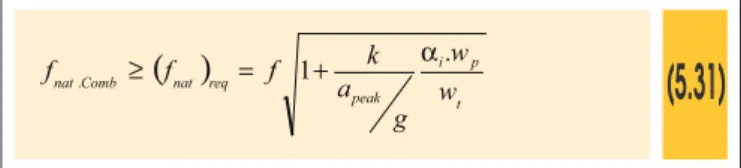
The natural frequency calculated according to section 5.6.1 should be compared with the minimum natural frequency required in Table 5.3, interpolating, when necessary, for the obtainment thereof ac -cording to the characteristics of the loor under analysis in relation to those speciied in table 5.3. This calculated natural frequency, being less than the required tabulated minimum natural frequency, indicates that the loor cannot be accepted, thus proceeding to a second analysis, now using the following expression:
(5.31)
( )
t p i
peak req
nat Comb
nat w
w
g a k f
f
f . ³ = 1+ a.
In this expression, the terms are deined as follows: nat
f – Natural frequency of the loor system under analysis
(
fnat)
req– Minimum natural frequency required at each forced frequencyf – Excitation frequency as shown in Table 5.4,
f = if
stepstep
f – Pitch frequency of the activity
i
– Harmonic under analysis as shown in Table 5.4k
– Constant depending on the type of use of the loorDancing room = 1.30 Lively concert = 1.70 Sporting events = 1.70 Aerobic activities = 2.00
α
– Dynamic coeficient according to Table 5.4Table 5.2 – Recommended values for the parameters of equation 5.30 and limits (a /g) due to walking
peakType of floor usage
Constant force
(P ) (kN)
0
Damping
(
b
)
Peak/Gravitational acceleration
(a /g)x100%
peakOffices, homes and churches without walls,
ceilings or platforms (decks)
Offices, homes and churches with removable
dividers and non-structural components
Offices with partitions, walls between floors
Malls and shopping centers
Footbridges – indoor
Footbridges – outdoor
0.29
0.29
0.29
0.29
0.41
0.41
0.02
0.03
0.05
0.02
0.01
0.01
0.50%
0.50%
0.50%
1.50%
1.50%
5.00%
(1)
frequency
(Hz)
(f)
Weight of users
2(kN/m )
Total weight
(kN/m )
2natural frequency
Minimum required
(3)(w )
p(w )
t(H )
zActivity
Threshold peak acceleration
Type of construction
3.00
3.00
0.6
0.6
5.6
3.1
6.4
8.1
5.00
5.00
1.5
1.5
6.5
4.0
(2)
5.9
(2)
6.4
8.25
8.25
4.2
4.2
5.2
2.7
(2)
8.8
(2)
9.2
8.25
5.00
2.5
2.5
5.12
2.62
(2)
9.2
(2)
10.6
Source: MURRAY, ALLEN & UNGAR (2003)
Notes: (1) - E quation 5.31 is provided for all harmonics listed in Table 5.4 where the excitation frequency that governs the movement is shown (2) - M ay be reduced if, according to equation 5.33, the product of the damping and the mass is sufficient to reduce the resonance
of the 2nd and 3rd harmonics to an acceptable level. (3) - V alues calculated based on equation 5.31.
Dancing and dining
Lively concerts and sports events
Aerobic exercises only
Jumping exercises and weight lifting
2
Heavy floor – 5.0 kN/m
2
Heavy floor – 5.0 kN/m
2
Heavy floor – 5.0 kN/m
2
Heavy floor – 5.0 kN/m
2
Light floor – 2.5 kN/m
2
Light floor – 2.5 kN/m
2
Light floor – 2.5 kN/m
2
Light floor – 2.5 kN/m
Rate of acceleration –
0 =0,02g a
Rate of acceleration –
Rate of acceleration –
Rate of acceleration –
05 , 0
0 =
g a
06
02 ,
, 0
0
0
0 =
=
g
g a
a
Table 5.4 – Estimated load for rhythmic events
Excitation
frequency
(Hz)
(f)
Weight of users (*)
2(kN/m )
coefficient
Dynamic
Dynamic load
(kN/m )
2(w )
p(
a
i)
(
a
iw )
pActivity
Dancing
1st harmonic
Lively concert
1st harmonic
2nd harmonic
Sports events
1st harmonic
2nd harmonic
Jumping exercises
1st harmonic
2nd harmonic
3rd harmonic
1.50–3.00
1.50–3.00
3.00–5.00
1.50–3.00
3.00–5.00
2.00–2.75
4.00–5.50
6.00–8.25
0.60
1.50
1.50
1.50
1.50
0.20
0.20
0.20
0.50
0.25
0.05
0.25
0.05
1.50
0.60
1.00
0.300
0.400
0.075
0.400
0.075
0.300
0.120
0.020
Source: MURRAY, ALLEN & UNGAR (2003)
g
apeak – Percentage of peak acceleration/ gravitational acceleration
p
w – Weight per unit of area of the participants distributed on the loor
t
w – Total weight per unit of area of the participants and of the loor
Important note:
The portions relating to weights
w
p andw
t, should beconsid-ered in the entire area of the structural system of the loor under analysis.
Expression 5.31 should be used for all harmonics listed in Table 5.4, substituting the terms thereof according to the aerobic activity to which the loor is subjected.
According to the foregoing criterion, the percent ratio of peak ac-celeration in relation to gravitational acac-celeration can be calculated by the expressions presented below, where appropriate. Similarly, as stated in item 5.6.4, the maximum acceptable levels for the ratio between peak acceleration in relation to gravitational acceleration are shown in the abacus in Figure 3.2.
Case 1:
In resonance, situation whereby there occurs the sum of the sys -tem’s natural vibration energies with those of the forced vibration at the time when they are equal
f
nat.Comb=
f
expression 5.31 can be rearranged to the following format:(5.32)
tp i peak
w
w
g
a
a
b
2
30
,1
=
In this expression
β
represents the damping rate of the structural system. The result of expression 5.32 should be less than the per-centage ratio of peak acceleration in relation to gravitational ac -celeration speciied in the irst column of Table 5.3, just below the intended use of the loor.Case 2:
Out of resonance, in which fnat.Comb≥1,2f, and expression 5.30, are transformed into:
(5.33)
t p i
for nat peak
w w
f f g
a a
1 30 , 1
2
-÷ ø ö ç è æ =
Finally, when the harmonic excitation frequency
f = if
step, wherei
represents the harmonic of interest, is equal to or shown to be very close to the natural frequencyf
nat of the structural loor sys -tem, its percentage acceleration of peak acceleration in relation to gravitational acceleration should be calculated by expression 5.31. In cases where the lowest harmonics exhibit levels of excita-tion frequencies far from the natural frequency, the ratio of peak acceleration to gravitational acceleration should be calculated by expression 5.33 for the harmonic of interest.6. Numerical application
Exemplifying this information numerically, it is assumed a loor slab originally designed for ofices, for which one irst wishes to verify
the acceptability thereof when subjected to users walking, and sec -ondly, due to the change of use, when subjected to aerobic loads due to the addition of a dance loor. This loor slab, due to its char -acteristics of initial use and after modiication, falls under the irst row of Table 5.2 for the purpose of obtaining the initial information necessary for the calculations and in Table 5.3 in the inal analysis. Table 5.5 shows the input data of the numerical example for verii -cation of loor as shown in Figure 5.2.
So, by making the substitutions of these initial values appropriately in the respective expressions shown previously, according to the script shown, one arrives at the percentage value of peak acceler -ation in rel-ation to gravit-ational acceler-ation
g
aPeak of calculation.
Once these values are obtained, a comparison is made between the calculated values and the thresholds
g
aPeak recommended in
Table 5.2. If g aPeak
calculated is less than the equivalent tabulated value, one can conclude that for the initial proposed data, the ex-empliied loor slab satisies the minimum conditions capable of avoiding the harmful effects of vibrations. Otherwise, it does not meet this condition.
In this case, the loor – as initially speciied – would satisfy the veriication with regard to walking, and would not satisfy if a dance loor were to be added.
In the dynamic veriication of the loor when walking, the rate of peak acceleration relative to gravitational acceleration would reach 0.31%, a value below the maximum acceptable limit of 0.50% (Ta -ble 5.2). In the veriication as to dancing on the dance loor added thereto, the rate of peak acceleration in relation to gravitational acceleration would reach 4.13%, lower than the acceptable limit of 5.00% (Table 5.3), but the minimum acceptable natural frequency would be below the required threshold of 10.84 Hz calculated by expression 5.31, reaching only the value of 10.46 Hz.
Therefore the loor, in the case of adding a dance loor, would re-quire technical intervention to adjust the natural frequency calcu -lated by expression 5.28 to the minimum acceptable natural fre-quency required, obtained through expression 5.31.
7. Conclusion
According to standard ABNT NBR 6118:2007, the dynamic analy -sis for the structural element examined in this article would only be met with the calculation of the natural frequencies thereof, and subsequent comparison of these results with the respective critical frequencies shown in Table 2.2, satisfying the inequality fnat>1,2fcrit
and the acceptable maximum displacements recommended in Ta-ble 2.1; the two conditions must be met simultaneously.
Standard ABNT NBR 8800:2008 lists several minimal criteria to be considered, however does not detail them numerically, suggesting texts of international origin for the purposes of consultation and categorization of the dynamic analysis under examination. This article presents the development of calculations relating to a dynamic analysis of a loor, allowing for an analysis in two cases and obtaining the dynamic response when subjected to actions of human activities due to walking and aerobic activities such as dancing. For the other aerobic activities listed in Tables 5.3 and 5.4, the procedure is the same.
of simple computer systems, thereby securely meeting the most immediate and expeditious needs of the professionals involved in this type of analysis.
Ends up suggesting numerical values that can be replaced in the sequence of formulas and theoretical considerations presented, thereby enabling a inal examination of the various aspects of inter -est involved in the dynamic analysis of loors, such as the type of occupancy, the human excitation load, the damping ratio, and the acceptable percentage of threshold acceleration, according to the international literature, in addition to meeting Brazilian regulatory recommendations.
The calculated values were compared with the tabulated values in the inal analysis on the acceptance of the loor in relation to the vibrations caused by walking. It is checked whether the calculated values are below the limits speciied in Tables 5.2 and 5.3, accord-ing to the respective speciied use of the looraccord-ing.
It is observed with this relatively simple sequence of calculations that one can quickly and eficiently conduct the analysis of loors with regard to vibrations due to human activities to which they are submitted, as a function of the diverse and possible uses thereof, making it possible to make speedy technical decisions able to guide the need for more elaborate analyses, guiding any possible prelimi -nary and immediate physical interferences in the structural elements examined for the purpose of mitigating user-induced vibrations.
8. Acknowledgments
The authors would like to thank CNPq, CAPES, and FAPES for the support received for conducting this study.
9. References
[01] ASSOCIAÇÃO BRASILEIRA DE NORNAS TÉCNICAS –
Table 5.5 – Input data of the numerical example
Beams in directions
Secondary
Primary
Description
Unit
Slab
Type
Dimension in secondary direction
Dimension in primary direction
Floor slab table height
Floor slab ribbing height
Characteristic strength of concrete
Modulus of elasticity of the concrete
Modulus of elasticity of steel beams
Variable load on the floor
Permanent load on the floor
Distance between the axes of the beams
Mass per linear meter of steel beams
Cross-sectional area of steel beams
Moment of inertia of the steel beams
–
cm
cm
mm
mm
MPa
GPa
GPa
2kN/m
2
kN/m
mm
kg
2
mm
4
mm
Mixed
800
800
70
50
25
28
–
0.70
4.36
–
–
–
–
W460x60
800
800
–
–
–
–
200
–
–
3000
60
7,620
256.52x10⁶
W460x60
800
800
–
–
–
–
200
–
–
8000
60
7,620
256.52x10⁶
Source: PRETTI – AutorABNT. Projeto de Estruturas de Concreto. Procedimento. ABNT NBR 6118. Rio de Janeiro: ABNT, 2007
[02] ASSOCIAÇÃO BRASILEIRA DE NORNAS TÉCNICAS – ABNT. Projeto e Execução de Estruturas de Aço de Edifí -cios. Procedimento. ABNT NBR 8800. Rio de Janeiro: ABNT, 2008
[03] INTERNATIONAL ORGANIZATION FOR STANDARDIZA-TION – ISO – Mechanical Vibration and Shock – Evalua -tion of Human Exposure to Wholebody Vibra-tion – Part 1: Vibration in Buildings (1 Hz to 80 Hz) – ISO 2631:1 – 2ª Ed – 05/01/1997
[04] INTERNATIONAL ORGANIZATION FOR STANDARDIZA -TION – ISO – Mechanical Vibration and Shock – Evalua-tion of Human Exposure to Wholebody VibraEvalua-tion – Part 2: Vibration in Buildings (1 Hz to 80 Hz) – ISO 2631:2 - 2ª Ed – 04/01/2003
[05] MURRAY, T.M; ALLEN, D.A; UNGAR, E.E. Floor Vibrations Due to Human Activity – Steel Design Guide Series 11 – 2º Ed – Chicago: AISC – American Institute of Steel Construc-tion Inc., 2003.