*e-mail: [email protected]
1. Introduction
The widespread use of aluminum as a structural and functional material is driving the development of new cost effective and environmentally friendly methods of aluminum recycling. Aluminum beverage cans are the largest components of processed aluminum scrap. An important application of aluminum scrap from cans is the production of alloys A319 or A380 which are used in automotive industry. However, these alloys specify no more than 0.10 wt. % Mg to avoid the harmful effects on mechanical properties1. The removal of magnesium from molten aluminum alloys can be accomplished by using one of the following methods: Chlorination injection, electrochemical process and the submerged powder injection technique. The chlorine injection method2,3 is commonly used, but the pollution generated limits its application. The electrochemical method4,5 is a clean but expensive treatment due to the high cost of electrical energy. Flores et al.6 showed that it is possible to achieve magnesium removal from Al-Si-Cu-Mg alloys by submerged injection of SiO2 particles. Escobedo et al.7. presented a kinetic study on the magnesium removal by injecting silica particles with argon as carrier
gas in aluminum alloys (gas-injection treatment). They found that it was possible to reduce magnesium from 1.2 to 0.02 wt%, and the global process rate was increased when the particle size was decreased. The gas-injection treatment produced solid wastes which were handled easily and gas pollution was avoided. Gas-injection treatment or powder injection process has gained importance as a means to carry out smelting and reining reactions due to the intimate contact between particle and metal. In addition, the gas jet provides mixing of the molten metal to achieve chemical homogeneity (gas-stirring treatment). There are two possible reactions zones in the injection process8.These are, the transitory reaction zone (reaction between the particles injected and liquid metal) and the permanent reaction zone (reaction between the metal-slag interfaces). An important parameter for transitory reactions is the residence time of the particles inside the ladle. The residence time is deined as the time that the particles spend inside the melt before surfacing once they have been released from the nozzle of the lance, and it is determined by its velocity relative to the melt and by the bulk low velocity of the melt. If the particles have low settling velocities, their motion will be
Application of Computational Fluid Dynamic in Aluminum Reining
Through Pneumatic Injection of Powders
Jorge Enrique Rivera-Salinasa*, Victor Hugo Gutiérrez-Pérezb, Mariza Vargas-Ramírezc,
Karla Monzerratt Gregorio-Jáureguib, Alejandro Cruz-Ramírezb, Felipe Avalos-Belmontesa,
José Carlos Ortíz-Cisnerosa, José Concepción Escobedo-Bocardod
aDepartamento de Materiales, Universidad Autónoma de Coahuila, Boulevard V. Carranza y José Cárdenas Valdés, 25280 Saltillo, Coah, México
bDepartamento de Ingeniería en Metalurgia y Materiales, Instituto Politécnico Nacional, Escuela Superior de Ingeniería Química e Industrias Extractivas – ESIQIE,
UPALM, 07738, México D.F., México
cCentro de Investigación en Metalurgia y Materiales, Universidad Autónoma del Estado de Hidalgo, Carretera Pachuca-Tulancingo Km 4.5, 42084, Pachuca-Hgo, México
dDepartamento de Metalurgia, CINVESTAV Unidad Saltillo, Carretera Saltillo-Monterrey Km 13.5, Apdo. Postal 663, 25900, Saltillo, Coah, México
Received: February 20, 2014; Revised: September 14, 2014
Magnesium removal process from molten aluminum using particles of silica sand was studied from a hydrodynamic point of view using computational luid dynamics (CFD). The gas-liquid low was modeled by a model of the Euler type for both gas and liquid phase transport. Newton´s law of motion was used to describe the subsurface motion of injected solid particles from the calculated low ield in one-way coupling. The kinetics of the transitory reaction was described by using the model proposed by Ohguchi and Robertson for transitory reactions. The contacting method of reaction for silica particles of 75, 210 and 425 µm was established according to its dynamic interaction with the two phases low. When the particle size was increased, the residence time increased as well; however, the eficiency for the transitory reaction was decreased. The reaction rate simulation showed a good agreement with experimental results reported in the literature.
controlled by the bulk circulation generated by the bubble plume with a relative long travel inside the melt. If they remain in the vicinity of the lance tip upon injection, they will be rapidly carried by the plume to the upper surface of the melt, with low utilization eficiency on the kinetics9. The effectiveness of the injection technique is intricately related to the hydrodynamics of the system and the main parameters to consider are the low regime, relative velocity between particles and luid and particle trajectories, aspects that depend principally on the gas plume structure behavior within the ladle. Physical properties of the materials are very important too, as well as the particles discharge velocities, solids loading, and geometrical factors, etc.
The reagent eficiencies are typically associated with the residence time of the particles inside the melt which normally is quite short (a few seconds), thus eficiencies are often low10. The high temperature involved in the process and the opacity of metal means that is extremely hard or impossible to measure experimentally the particle trajectories in metallurgical systems, so other methods must be used to overcome this limitation.
Computational luid dynamics (CFD) has provided a mean for increasing the understanding of the dynamic interaction of multiphase and multicomponent systems in metallurgical operations. Quantitative information of gas-liquid low is the irst step necessary for modeling particle trajectories and mass transfer and chemical reaction in powder injection processes. There are two main model approaches used for the simulation of gas-liquid lows; these are the Eulerian-Lagrangian viewpoint which track bubbles as discrete particles and the Eulerian-Eulerian method, popularly known as the as the two luid model which assume each phase to be continuous and distinct11. The movement of the interface is naturally amenable to a Lagrangian description; while the bulk low is conventionally solved in an Eulerian framework. A conceptually straightforward way of handling the moving interface is to employ a moving mesh that has grid points on the interface and deforms according to the low. However, these methods break down when large displacement of internal domains cause mesh entanglement or when the interfaces undergo singular topological changes such as breakup and coalescence. As an alternative, the ixed-grid methods have been developed to regularize the interface, between these, the diffuse interface method has been used recently. The employment of the diffuse interface method changes the Lagrangian description of the interface motion into an Eulerian description which enables handling the moving interface. Instead of computing the low of the two components with matching boundary conditions on the interface, these methods represent the interfacial tension as a body force or bulk stress spread over a narrow region covering the interface. Then a single set of governing equations can be written over the entire domain and solved on a ixed grid in a purely Eulerian framework12. This paper presents two-dimensional (2D) multi-phase luid dynamic model using the diffuse interface method to predict the behavior of argon gas injection in molten aluminum, and to describe from the calculated low ield, the trajectories and residence time of silica particles injected using three different particle sizes of silica sand (75, 210 and 425 µm). Furthermore, the hydrodynamic model incorporates mass
transfer and the kinetics of transitory reaction during magnesium removal from aluminum molten alloy by silica particles at lab scale. The constitutive equations are solved using the Petrov-Galerkin inite element method (FEM) code that is implemented in the commercial software COMSOL Multiphysics. In order to validate the model, numerical results were veriied against experimental data reported previously7. Numerical results for the progress of the rate of reaction agree well with the experimental measurements.
2. Fluid-dynamic Model
The process of submerged injection of powders through a lance into molten metal is shown in Figure 1. The experimental conditions and the relevant physical data used for the model resolution are given in Table 1. Figure 2 shows the physical dimensions of the top-submerged gas injection process at lab scale. The CFD modeling for injection process was formulated by using the coupled Navier-Stokes/Phase-Field system to model the low induced by the argon gas and to describe the dynamic evolution of the interface layer between gas plume-liquid metal.
2.1. Basic equations
The diffuse interface (DI) method offers an attractive alternative to more established methods for solving multiphase flow problems such as volume-of –fluid (VOF), level set (LS) and front tracking which seem to
Table 1. Experimental conditions and physical properties.
Conditions Value
Gas low rate 2 Χ 10–4 m3 s–1
Inner lance diameter 0.375 Χ 10–2 m
Outer lance diameter 5 Χ 10–2 m
Property Material Value
Density aluminum
argon silica particles
75 (μm) 210 (μm) 425 (μm)
2350 kg m–3
(Pmanometric +
Patmospheric)/RT kg m–3
2840 kg m–3 2830 kg m–3 2850 kg m–3 Kinematic
viscosity
aluminum argon
1.05e-3 Pa s 5.35e-5 Pa s
Surface tension aluminum-argon 0.84 N m–1
suffer from problems with either mass conservation or the accurate computation of surface tension. Previous simulation in rising bubble and droplet entrainment for lows with large density and viscosity ratios (gas and liquid) have shown that the DI method has the capability to treat the gas/liquid interface problem adequately13. The method was applied here to simulate the gas plume behavior during the downward injection of gas into molten metal contained in a ladle. In the DI methods, instead of directly tracking the interface between two luids, the interfacial layer is governed by a phase-ield variable f
that obeys a Cahn-Hilliard type of convection-diffusion equation14, which is a measure of the relative composition or volume fraction of the two components. The surface tension force is added to the Navier-Stoke equation as a body force by multiplying the chemical potential of the system by the gradient of the phase-ield variable, this form facilities an energy law to be satisied by the inite-element weak form. An equivalent form for the body force has been reported by Yue et al.15. The free energy density of an isothermal mixture of two immiscible luids is comprised of the sum of the mixing energy and elastic energy. The mixing energy assumes the Ginzburg-Landau form16 according with Equation 1.
(
)
2(
)
22 2 1
, 1
2 4
mix
f f ∇f = l∇f + l f −
b (1)
where f, is the dimensionless phase ield variable. The volume fraction of the components of the luid are (1 + f)/2, and (1 – f)/2; l is the mixing energy density, and b is a capillary width that scales with the thickness of the diffuse
interface. As b→ 0, the ratio l/e produces the interfacial tension s in the classical sense14-17:
2 2 3
l s =
b (2)
The evolution of the phase ield variable is governed by the convective-diffusion Cahn-Hilliard equation18,19, which is a 4th-order PDE.
2 G t
∂f+ ⋅∇f = g∇
∂ u (3)
where u is the velocity of the luid,
(
)
2 2
2 1 G
f f −
= l −∇ f + b
is the chemical potential and γ is the mobility. The mobility determines the time scale of the Cahn-Hilliard diffusion and must be large enough to retain a constant interfacial thickness but small enough so that the convective terms are not overly damped. The mobility is determined by a mobility tuning parameter that is a function of the interface thickness16:
2
g = cb (4)
Similar to the VOF method, the volume fraction of one of the luids is used to indicate the composition of the two components in a volume element in the domain. In the DI methods the Cahn-Hilliard equation forces f to take a value of 1 or -1 except in a very thin region on the luid/luid interface. The Cahn-Hilliard equation requires particular attention. With C0 elements, which are smooth within each element and continuous across their boundaries, one cannot represent derivatives higher than 2. Thus, the fourth-order Cahn-Hilliard is decomposed into two second-order partial differential equations:
2 t
∂f+ ⋅∇f =gl∇ψ
∂ u b (5)
(
)
2 2 1
ψ = −∇b ∇f + f − f (6)
The conservation of momentum can be expressed in terms of the Reynolds average Navier-Stokes equations (RANS) with the addition of the phase-ield surface force implemented as a body force Fst14-20:
(
)
(
)
(
T)
t g st
p t
∂
r + r ⋅∇ = ∇ ⋅ − + h + h ∇ + ∇ + +
∂
u
u u I u u F F (7)
0
∇ ⋅ =u (8)
where r is the density of the mixture, computed by:
r = r1 + (r2 – r1)Vf, and the dynamic viscosity according to:h = h1 + (h2 – h1)Vf, r1 and r2 are the densities and h1 and
h2 are the dynamic viscosities of the argon gas and liquid
aluminum, respectively. The volume fraction of luid 2 is
computed as: Vf = min(max([(1+f) /2],0),1), where the min and max operators are used so that the volume fraction has a lower limit of 0 and an upper limit of 1. The surface tension force is: Fst = G∇f, and Fg = rg, where g is the gravitational acceleration. Turbulence models with wall functions coupled to Reynolds average Navier-Stokes equations is an effective Figure 2. Dimensions of the ladle-lance system used for the
and practical tool for describing this class of problems21. Therefore, Reynolds stresses or turbulence stress of the RANS model is expressed in terms of turbulent viscosity and the standar k – e model.
2 / t Cm
h = r κ e (9)
where ht is the turbulent viscosity Cm is a turbulence model constant, k is the eddy kinetic energy and e is the turbulent energy dissipation rate.
Equations 5-9 together with the transport equations for k and e form the governing equations for the bath agitated by gas injection through a top submerged lance.
2.2. Model assumptions
For this model, the following assumptions were considered: (1) Unsteady state conditions were used for the two-phases; (2) The gravity force acts along the plume axis; (3) The shape and interaction (coalescence and break
up) of the bubbles were determined by the phase-ield
model; (4) The metal is isothermal at 1023K; (5) Liquid density is assumed to be constant, and gas density varies depending on local pressure according to ideal gas law;
(6) Flat free liquid surface; (7) Particle concentration is
low, then the motion of the particles is determined by
the luid low, but the particle motion does not inluence the luid low (One-way coupling). It is to say that the luid low behaves in the same manner as it would if no
particles were present.
2.3. Boundary conditions
Boundary conditions applied to phase ield model are
shown in Figure 3. At the walls, the velocities satisfy the no slip condition. The values of k and e near wall points and friction on the walls were calculated using the logarithmic law of the wall16. At the nozzle exit, the supericial gas velocity was set to 18.1 m/s and the volume fraction Vf , was speciied in 1 for the gas phase while the Vf for the liquid was set to 0. The boundary conditions for turbulence parameters k and e at the nozzle were estimated as a function of the supericial gas velocities. A degassing condition (lat liquid free surface) was imposed for the outlet domain and zero gradient for k and e were introduced at the free surface21. The phase ield function must to be initialized such that it varies smoothly from -1 to 1 across the interface. The contact angle qw between the liquid metal and the solid wall was set to p/ 2, according to Equation 10, to consider the effect of low wettability system
(
)
(
)
2 2tan / 2 0
w
⋅b ∇f = b p − q ∇f − ⋅∇f =
n n n (10)
3. Mass Transfer Model
The magnesium transport through the low of molten
metal was modeled with the transport of diluted species
(
)
Mg
Mg Mg t Mg Mg
c
c D D c R
t
∂
+ ∇ = ∇ ⋅ + ∇ −
∂ u (11)
where cMg represents the magnesium molar concentration dissolved in the molten, DMgis the laminar diffusion
coeficient in the mixture (assumed to be 2.43 x 10⁻¹¹ m2/s)22,
Dt is the turbulent diffusivity. On the right-hand side, the RMg term represents consumption of Mg due to chemical reaction and it was estimated considering the chemical transitory reaction.
3.1. Chemical transitory reaction
The magnesium removal from liquid aluminum with silica particle injection is carried out with reaction (12)7
Mg + 2Al + 2SiO2 = MgAl2O4 + 2Si (12)
The reaction takes place at the interface between particle and the liquid metal. In the current simulation the model proposed by Ohguchi and Robertson23 was used to model the kinetics of transitory reaction in the magnesium removal from aluminum alloy in a small scale system.
[ ]
[ ]
2
SiO Mg Mg
d Mg Mg
J EL R
dt
− = =
w (13)
where w is the mass of aluminum alloy, JSiO
2 is the injection
rate of powder, E is a measure of the eficiency of the transitory reaction and its value can vary between 0 and 1. A value of E =1 indicates that the equilibrium with respect to magnesium is attained instantaneously between the particle and the surrounding liquid aluminum. LMg is the equilibrium magnesium partition ratio between slag and metal:
(
)
[
%%]
Mg
eq Mg L
Mg
= (14)
magnesium content in thermodynamic equilibrium at the process temperature in the bath metal. LMg was calculated in 55.882 at 750 °C7. Since the transitory reaction is determined by the number of particles (effective area) and its uprising velocities through the bulk metal, the term JSiO
2
was expressed as24:
2 2 2
SiO p SiO SiO
J =U A r (15)
where Up is the particle velocities, ASiO
2is the surface area
of particle in contact with the melt, and rSiO
2 is the density
of silica powder.
3.2. Boundary conditions
Mass lux was set to zero for all boundaries, n.N = 0, N = – DMg∇cMg + cMgu.
4. Particle Tracing
The eficiency of transitory reaction (E) is a parameter
that depends on many aspects, such as the subsurface trajectories of particle injected into the melt, its residence time and the proper contacting method to react chemically.
These aspects are directly related to the gas-liquid low
system behavior; therefore, knowing the direction and
velocities of gas-molten low inside the ladle during the
pneumatic injection, it is possible to predict the motion of particle immersed into the melt and gas.
In general, the equation of motion of particle in the
presence of an external ield can be written on the basis of
Newton’s second law
2
2 , ,
d d
m t
dt dt
=
x x
F x (16)
where X is the position of the particle, m is the particle´s mass, t is time and F is the sum of all forces acting upon the particle. The subsurface trajectory of a particle together with its apparent or added mass is governed by drag, buoyancy and gravity forces; history term is only of minor importance in determining particle trajectories. Other component that forms part in the forces balance in particle motion during impact with liquid surfaces (particle projection into molten) is the surface tension force; the impact of particles with a liquid free surface is generally accompanied by the formation of a cavity when the solid irst enters the liquid, however in this work the effect of surface tension was not accounted for25. The rapid decelerating of the particle during impact was based on the drag and the characteristics of the low approaching the solid according the gas or liquid phases. The drag force represents the force that a luid exerts on a particle due to a difference in velocity between the luid and the particle. In this work the drag force was estimated using the empirical equation proposed by Khan and Richardson26:
(
)
3.452 1.84 Re 0.31 0.293 Re0.06
p p p p p
r −
= p r − − +
F u u u u (17)
Equation 17 is valid for spherical particles in a wide range of particle Reynolds numbers. The Reynolds particle number is deined as:
2 Rep p p
r
− r
= h u u
(18)
where up is the particle velocity and rp the particle radius. Equation 16 together with u = dx /dt constitute a set of nonlinear ordinary differential equations, subject to the initial conditions that at t = 0 and x = 0, u = uinlet gas.
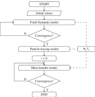
5. Numerical Solution Procedure
The governing equations were solved numerically
by the Petrov-Galerkin inite-element method using the
commercial software COMSOL Multiphysics and according to the flow chart shown in Figure 4. The ladle-lance
system was simulated with an unstructured reined mesh
(3200 elements, 27891 degrees of freedom). The time coordinate was discretized by using the backward difference formulas (BDF), this technique is a semi-implicit scheme
unconditionally stable which lets basically any use of ∆t without concern about stability. However the time step size is, of course important for accuracy, then the time step in the simulation was restricted using the Courant-Friedricks-Lewy (CFL) condition such that 2 ≤ CFL ≤ 10 to guarantee temporal accuracy and numerical stability.
u t CFL
h
∆ =
∆ (19)
where u is a representative velocity and ∆t and ∆h characterize the time step and the smallest distance between boundary nodes, respectively. Ordinary differential equations for particles trajectories were solved by the Runge-Kutta 5th order method from the data of low ield calculated previously. For the time evolution in the mass transfer model, a time step of 1 second was considered. The phase ield theory introduces three modelling parameters,
lbg which must be chosen judiciously by the situation to study, not only to retain some control of the topological
events but also to conserve the volume of the luids. Yue14 have validated values of these parameters connected to an adaptive meshing, which let handling large interfacial morphological changes.
6. Results and Discussions
The aim of the current research is to investigate numerically the dynamic interaction of the three phase
low system (liquid-gas-solid) in the course of pneumatic
injection, from the perspective of CFD resources to predict the effect of subsurface motion of particles on the progress
of transitory reaction in aluminum reining at laboratory
scale. Such information provides useful indications on the feasibility of using silica sand to remove magnesium with the injection technique. The evolution of interfacial layer between the argon and liquid aluminum is described with
the phase ield variable (f). The range of time studied in the simulation considers only the effects of transitory reaction for silica particles of 75, 210 and 425 µm conveyed to a
supericial gas velocity equal 18.1 m/s. The model proposed
by Ohguchi and Robertson23 was used to describe the kinetics of the transitory reaction. Those results were compared with experimental data from previous experimental work reported by Escobedo et al.7 in order to validate the model.
6.1. Bubble formation at the lance tip
The primary bubble formed at the nozzle of the lance is shown in Figure 5. The snapshots at different time show the shape of the bubble while it is growing at the lance tip when argon is injected through a top submerged lance made of graphite which the liquid aluminum does not wet. Initially the bubble grows attached to the internal diameter of the lance, when the bubble still growing, it continually spreads over intermediate positions between the inner and
outer diameter of the lance. When the bubble reaches the
outer diameter of the lance it expands radially until the equilibrium contact angle is reached.
Then the bubble begin to grow surrounding the lance tip due to the low wettability of the system until the bubble
tends to expand vertically (as it is shown in Figure 6a). As can be seen in Figure 5f the diameter of bubble generated at the nozzle tip was greater than the outer diameter of the nozzle. Figure 5 shows that, the volume of the gas bubbles detached is determined principally by the outer diameter of the lance due to the nonwettability of the nozzle. This gas injection behavior is in agreement with the reported by Irons and Guthrie27.
6.2. Fluid low behavior by injection gas
Figure 6 shows the low structure in the ladle, where the lines and arrows represent the streamline patterns and
the low direction, respectively. Figure 6a shows that the
low in the ladle is almost symmetrical until 0.61 s, when
the plume impinges on the free surface of the bath, the
low becomes unstable and then the gas plume is broken
up in bubbles that began to detach from the upper part of the plume. This behavior of discrete bubbling pattern was maintained for almost 0.66 s (Figure 6b). However, as injection time proceeds, the inertia of the liquid pushes the gas plume aside the axis of the lance (Figure 6c), this behavior prevailing for the rest of the injection time considered in the simulation (simulations were performed until a periodic oscillatory-state was observed). As can be seen a pattern transition is presented from discrete bubbling
low to a gas channel through the liquid and lance. This
plume behavior can be expected due to the small vessel
aspect ratio (metal high/ diameter of vessel ̴1) and the high
gas injection rate28. The vessel aspect ratio and gas injection rate play important role on the pattern and the structure of
low in the bath. Obtaining of this pattern in the low under the current operating conditions affects the mixing eficiency
due to the relative small radial extent of the gas plume, besides the interaction between the two phases is due to the shearing between the gas column and liquid, leading to a low liquid entrainment into the rising plume as it can be seen in the left upper part of the ladle in Figure 6a, where a liquid drop in the gas stream can be appreciated. However, the meandering movement of the gas column displaces the liquid in the region where the liquid and gas coexist,
causing recirculating motions in the bulk of the liquid. Simulation results show that the oscillatory behavior of the gas plume tends to form recirculation zones inside the bath as is observed in Figures 6c and 6d. The oscillatory behavior of the plume consists of a stochastic motion of the whole plume. The gas plume structure shrinks and stretches
radially and axially which causes luctuations in velocity
components. The recirculation regions in the bath were random and transient in the bulk liquid metal, which were
considered as a suitable low to minimize compositional stratiication in the bath. No signiicant modiications in
the number of recirculation cells were observed with deeper
reinement. Plume oscillations behavior makes variable
the gas penetration; the largest distance of penetration in both directions (radially and axially) was located near the lance tip when the plume attains the maximum internal pressure (2219 N/m2) and then falls rapidly. Figure 7 shows
the average velocity low proile in the ladle associated to the molten aluminum and gas phases for a supericial gas
velocity of 18.1 m/s.
After the gas was injected, its kinetic energy was immediately dissipated, decreasing the bubble plume velocity. The highest upward velocity of the gas column due to the buoyancy force was found to be 7.1 m/s while
the liquid region presented a velocity of 0.2 m/s. The differences between the estimated velocities of each phase is due to small liquid high in the bath, which causes the gas channels through the liquid easily, as a result low interaction between the liquid and gas exist, thus the liquid circulation rate is low comparable with its counterpart when the vessel aspect ratio is higher and the radial extent of two phase gas liquid plume increases and the gas injected can interact more effectively with the liquid.
The color bar attached with Figure 7 indicates the velocity magnitude in the ladle.
6.3. Particle behavior and residence time
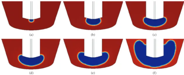
Three different particle sizes of silica sand (75, 210, 425 µm) of distinct density were studied in order to elucidate the hydrodynamic behavior of each situation (particle trajectories, maximum penetration distances and residence time) and the contacting method of reaction, after they were discharged into the bath to remove magnesium (particle may remain inside the bubble, on the surface of the bubble or in the liquid region10). It was observed that most of the particles of 75 µm do not pass through the interface gas-liquid.
the gas plume drag as is shown in Figure 8a. The average residence time was determined in 0.26 s for this particle
size. A signiicant number of particles of 75 µm were kept
on the interface gas-liquid for every time step. Therefore, for the particle size of 75 µm, the transitory reaction occurs in the liquid-particle-gas interface, and between the particles in the gas stream and the metal drops entrained
into the rising plume. The phase ield model may predict
the droplet entrainment in the gas stream, but it would be necessary many grid points in the solution domain (through
mesh reinement to ensure b<<R, where R is the radius of the droplet) which implies a higher computational cost. When particle size was increased to 210 and 425 µm, it was observed a raft of particles projected into the liquid after they leave the lance tip which would promotes the breakup of the gas-liquid interface (Figures 8b and c) letting particles descend through the liquid. The penetration distance of the particles into the molten metal was increased when the particle size was increased for the same entry velocity. It was observed that the particles were dispersed into the liquid as agglomerates of particles rather than individual particles. This behavior was more notorious for the particle size of 425 µm.
After the particles were injected, it was observed a particle agglomeration in the molten metal and then the convective movement of the liquid causes the breakup of the agglomerate. The residence time was determined in 0.44 and
0.53 s for the particle size of 210 and 425 μm, respectively. It was observed that a low number of particles of 210 and 425 μm were trapped by the stream of the carrier gas and the highest number of particles was exposed completely to the liquid metal. This behavior means that the transitory reaction between silica particle and dissolved magnesium was carried out in the liquid phase for the particle sizes of 210 and 425 μm. These results for the interaction of three phases low system are in agreement with those obtained in references29,30. For the particles of 210 and 425μm, it was observed that the particle jet does not expand signiicantly, and then the particle jet diameter will approximately equal the nozzle diameter. The effect of density on the deep penetration and retention time was the same for the three situations considering that the solid/liquid density ratio (≈1.2) is almost the same in each case. The residence time was increased with the increasing of the particle size. Therefore, smaller particles spend very little time into the melt while a larger travel time corresponds to bigger particle sizes. This behavior is expected since bigger particles are less affected to local velocity variations, which means that they move almost decoupled from the low, following their inertia10. The eficiency on the impurity removal in the alloy is strongly inluenced by the residence time of the particles. A low residence time indicates that particles will have less opportunity to react, thus decreasing the process eficiency. Figure 9 shows the trajectories of the particles inside the ladle for the three different particle size calculated at a supericial gas velocity constant of 18.1 m/s. Figure 9a shows the results for the particle size of 75 μm. In this igure some lineal trajectories can be seen, this is due to the meandering movement of the gas column projects some particles with enough kinetic energy, causing that they impact on the wall of ladle and then remaining in the vicinity of the wall, since the particles are not buoyant and the liquid is relatively quiescent in this region because of the no slip condition. Furthermore it is observed that some particles gradually settle in the bottom of the vessel. This explains why experimentally more inclusions are to be found with this particle size7. However, most of them remained at the interface gas-liquid during rising to the liquid free surface. Only a little fraction of the powders particles of 75 μm could penetrate into the melt remaining immersed as inclusions. As the most of the particle ascending inside the gas plume, only a fraction of their area is in contact with the molten metal to react. The results of Figures 9b and c correspond to the particle sizes of 210 and 425 μm, respectively. For these cases, most of the particles penetrate into the molten phase, after that, they were entrained and dispersed by the bulk recirculation of liquid caused by
Figure 8. Discharge of the particles, (a) particles of 75 µm, (b) particles of 210 µm and (c) particles of 425 μm. Figure 7. Average velocity low proile in the ladle for a supericial
the oscillation of the gas column. It was observed that the radial dispersion was increased when the particle size was increased, indicating that such particles have the tendency of being accelerated toward the luid velocity due to the drag, following the liquid low patterns and consequently can undergo prolonged subsurface motion. The particles of 425 μm were dispersed irst as agglomerates. In base to these results, a coarse particle jet presents some advantages on ine particle jets, like a later dispersion inside the ladle, a deep penetration, larger trajectories and therefore a larger residence time. However, it must be considered that increasing in the particle size, the effective area per unit volume is decreased, agglomerates are formed, and thus the mass transfer coeficient is affected as well as the chemical reaction.
6.4. Veriication of model predictions
In order to validate the model results, experimental and simulated normalized concentrations curves were compared. The convection-diffusion equation for mass transport was solved from CFD simulation and computing the parameters E and LMg for the source term based on the Ohguchi’s model23 and experimental data reported in the magnesium removal from an aluminum alloy7.The eficiency for the transitory reaction was estimated by using the Equation 20 taken from23.
2
1 exp SiO e e
Mg pow
A k
E
L V
− t = −
(20)
where E is the eficiency of the transitory reaction, ke is the
mass transfer coeficient, teis the residence time, LMg is
the equilibrium coeficient of Mg in the particle and Vpow is the particle volume. The average residence time estimated previously was used for the three different particle size (Figure 9). The mass transfer coeficient was determined using the equation of Sano et al.31.
1/ 4 2/3 5/12 0.4
Mg
e Mg
p D
k D
r
−
= + x n (21)
where xis the speciic mixing power and n is the kinematic
viscosity. The speciic mixing power was calculated by32:
370 1
1.48
QT H
Ln
x = +
w (22)
where Q is the volumetric low of conveying gas, T is the temperature of the melt, and H is the melt depth. The
eficiency of the transitory reaction was determined in 0.59, 0.41 and 0.27 for the particle size of 75, 210 and 425 µm, respectively. As it can be observed, the eficiency of the transitory reaction presented an opposite behavior with the residence time.
This means that, when the particle size was increased,
the residence time was increased too, but its eficiency
in removing magnesium from the aluminum bath was
decreased. A possible explanation for the high eficiency
and the short residence time estimated for the particle size of 75 µm is that the particles were rotating during their ascent the free surface of liquid. This rotation is caused by a very steep velocity gradient in the immediate proximity of the gas/liquid interface (where the particles were allocated),
and such rotation of the particles modiies the overall drag coeficient enhancing the mass transfer rate.
Furthermore, the fact that particles rotate during translation prevents the premature saturation of active sites, in other words, the particle-metal interface acted as if it was renewed. It is important to note that trajectories in Figure 9 were plotted as function of time and the trajectories that seem as if they were re-entering in the gas column were plotted in a previous time, where the structure of the gas was
different from the shown in this igure due to meandering
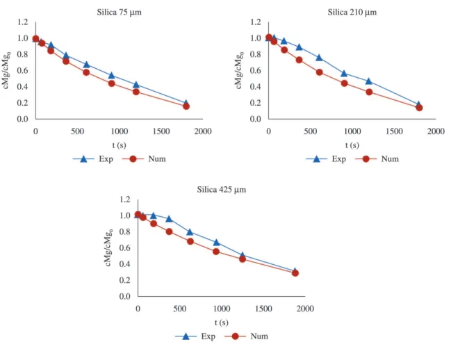
in the particle tracking model. Figure 10 displays the calculated variation of magnesium levels as a function of time compared with experimental data7 during demagging process. The results are presented in demagging fraction, which is calculated according with the following expression: Demagging = [cMg]/[cMg0]; where: [cMg] is the initial magnesium concentration and [cMg0] is the inal mass percent of magnesium.
Numerical results describe satisfactorily the time evolution of the Mg concentration in the liquid phase for the three cases studied. As it can be seen from the results of the present simulation and experimental data, particles of 75 µm reduce the magnesium levels faster than particles of 210 and 425 µm. This behavior was because of the current hydrodynamic conditions favor the particle size of 75 µm, owing to the fact that these particles have not too much momentum when discharged, and then are trapped by surface forces allocating them in the gas-liquid interface where a very steep velocity gradient is found which makes the particles rotate during their travel to free liquid surface avoiding their premature saturation at the boundary layer.
When particle size was increased, the particles penetrated
deeper into the ladle mainly as an agglomerate of particles. This hydrodynamic behavior does not favor the mass transfer rate, delaying the progress of the transitory reaction
at the beginning of the injection as it can be observed in the experimental data in Figure 10 for particles of 425 µm. For this particle size, the transitory reaction began to decrease the magnesium content 360 s after that the injection of particles had begun. The transitory reaction is assumed to start from the beginning of the injection in the numerical model, thus experimental data do not match very well for particles of 425 µm in this range of time. An increase in the
reagent low does not necessarily result in a high overall
conversion in the demagging process, because as it can be seen in this work the reaction rate depends strongly in the gas-particle-liquid interaction and the liquid-solid mass transfer, aspects determined by the hydrodynamic of the system. However with the present model the extent to
a parametric study to explore the mass low rate ratio of
powder to gas (loading) is limited to the regime where the particles and gas travel uncoupled. It should keep in mind that the present model proposes one-way coupling, and by increasing the solid/gas ratio the gas and particles travel at
about the same rate such that particles and gas lows in a
coupled state by changing the hydrodynamic behavior when the mixture enters in the liquid10,29. It must be noticed that the high loading effect on the hydrodynamic behavior cannot be accounted for within the scope of this study.
7. Conclusions
A 2D model for the gas injection characteristics, hydrodynamic behavior of particles and mass transfer in
demagging rate in aluminum reining in a small scale system
using the CFD modeling technique is presented. The results can be summarized as follows:
• The interaction of the gas and liquid phases such
as bubble coalescence, bubble break-up, droplet entrainment and plume meandering, for a metallic system was suitably simulated with the type
Cahn-Hilliard of Phase ield method.
• It was found that particles of 75 μm react at the
interface between gas-liquid metal while particles of
210 and 425 μm are exposed completely to the volume
of liquid metal to react.
• Despite that the particles of 75 μm exhibit the shorter residence time, they have the largest eficiency for
the transitory reaction. The current hydrodynamic conditions establish a proper contacting method of
reaction for these particles; as a result demagging rate was increased.
• The numerical computations clearly demonstrated the inluence of hydrodynamic contacting of the three
phases on the progress of the reaction. Numerical simulations have agreed satisfactory with the kinetic experimental results at lab-scale. CFD modeling technique is a useful tool to gain a clear understanding
of the way by which materials low through the reactor
and contact each other in order to react chemically in
ladle reining.
Acknowledgements
The authors wish to thank the Institutions CONACyT, SNI, COFAA and SIP-Instituto Politécnico Nacional for their permanent assistance to the Process Metallurgy Group at ESIQIE-Metallurgy and Materials Department. E. Rivera also would like to thank to M. S. Erubiel Córdova Rivera for his technical support.
References
1. Caceres CH, Davidson CJ, Griffiths JR and Wang QG. The effect of Mg on the microstructure and mechanical behavior of Al-Si-Mg casting alloys. Metallurgical and Materials Transactions. A, Physical Metallurgy and Materials Science. 1999; 30(10):2611-2618. http://dx.doi.org/10.1007/s11661-999-0301-8.
2. Tiwari BL. Demagging processes for aluminum alloys scrap. Journal of the Minerals Metals & Materials Society. 1982; 34(7):54-58. http://dx.doi.org/10.1007/BF03338052.
3. Neff DV. Impurity control in aluminum alloy melting processes using the gas injection pump. Transactions of the American Foundry Society. 1986:341-353.
4. Tiwary BL, Howie BJ and Johnson RM. Electrolytic demagging of secondary aluminum in a prototype. Transactions of the American Foundrymen’s Society. 1986; 94(86):385-390. 5. Tiwary BL and Sharma RA. Electrolytic demagging of
secondary aluminum in a prototype furnace. Journal of the Minerals Metals & Materials Society. 1984; 41-43.
6. Flores A, Muñiz R, Torres J, Macías E and Rodríguez N. Estudio del mecanismo de reacción durante la refinación de magnesio de aleaciones de aluminio líquidas usando partículas de SiO2. Revista Metal Madrid. 2008; 44(2):138-150. 7. Escobedo JC, Hernández, JF, Escobedo S, Flores A and Cortés
DA. Estudio cinético de la eliminación de magnesio en las aleaciones de aluminio mediante la inyección de polvos de sílice. Revista Metal Madrid. 2003; 39(161):172-182. http:// dx.doi.org/10.3989/revmetalm.2003.v39.i3.327.
8. Vargas M, Romero A, Morales R, Hernandez M, Chavez F and Castro J. Hot metal pretreatment by powder injection of lime-based reagents. Steel Research. 2001; 72(5):173-181. 9. Langberg D and Nilmani M. The injection of solids
using a reactive carrier gas. Metallurgical and Materials Transactions. B, Process Metallurgy and Materials Processing Science. 1994; 25(5):653-660. http://dx.doi.org/10.1007/ BF02655173.
10. Farias LR and Irons GA. A unified approach to bubbling-jetting phenomena in powder injection into iron and steel. Metallurgical and Materials Transactions. B, Process Metallurgy and Materials Processing Science. 1984; 16(2):211-225.
11. Mazumdar D and Guthrie RIL. The physical and mathematical modelling of gas stirred ladle systems. The Iron and Steel Institute of Japan. 1995; 35(1):1-20. http://dx.doi.org/10.2355/ isijinternational.35.1.
12. Feng JJ, Liu C, Shen J and Yue P. Advantages and challenges, modelling of soft matter. In: Calderer MCT and Terentjev EM, editors. Modeling of soft matter. New York: Springer; 2005. p. 1-26.
13. Ding H, Spelt P and Shu C. Diffuse interface model for incompressible two-phase flow with large density ratios. Journal of Computational Physics. 2007; 226(2):2078-2095. http://dx.doi.org/10.1016/j.jcp.2007.06.028.
14. Yue P, Zhou C, Fengh JJ, Olliver-Gooch CF and Hu HH. Phase-field simulations of interfacial dynamics in viscoelastic fluids using finite elements with adaptive meshing. Journal of Computational Physics. 2006; 219(1):47-67. http://dx.doi. org/10.1016/j.jcp.2006.03.016.
15. Yue P, Feng JJ, Liu C and Shen J. A diffuse-interface method for simulating two-phase flows of complex fluids. Journal of Fluid Mechanics. 2004; 515:293-317. http://dx.doi.org/10.1017/ S0022112004000370.
16. COMSOL Multiphysics. User’s guide CFD module, version 4.1. U.S., 2010.
17. Jacqmin D. Calculation of two-phase navier-stokes flows using phase-field modeling. Journal of Computational Physics. 1999; 155(1):96-127. http://dx.doi.org/10.1006/jcph.1999.6332. 18. Cahn JW and Hilliard JE. Free energy of a nonuniform system.
I. Interfacial free energy. The Journal of Chemical Physics. 1958; 28(2):258-267. http://dx.doi.org/10.1063/1.1744102. 19. Cahn JW and Hilliard JE. Free energy of a nonuniform system.
III. Nucleation in a two-component incompressible fluid. The Journal of Chemical Physics. 1959; 31(3):688-699. http:// dx.doi.org/10.1063/1.1730447.
20. Gurtin ME, Polignone D and Viñals J. Two-phase binary fluids and immiscible fluids described by an order parameter. Mathematical Models and Methods in Applied Sciences. 1996; 6(6):815-831. http://dx.doi.org/10.1142/S0218202596000341. 21. Schwarz MP and Turner WJ. Applicability of the standard
Mathematical Modelling. 1988; 12(3):273-279. http://dx.doi. org/10.1016/0307-904X(88)90034-0.
22. Callister WD. Introducción a la ciencia e ingeniería de los materiales I. Barcelona: Reverté; 2007: 106.
23. Ohguchi S and Robertson DG. Kinetic Model for Refining by Submerged Powder Injection: Part 1 Transitory and Permanent-Contact Reaction. Ironmaking & Steelmaking. 1984; 11(5):262-273.
24. Gutiérrez VH. Simulación Matemática de la Inyección de Polvos en Baños de Plomo. [Thesis]. México: ESIQUIE-IPN; 2011.
25. Guthrie RIL, Clift R and Henein H. Contacting problems associated with aluminum and ferro-alloy additions in steelmaking-hydrodynamic aspects. Metallurgical and Materials Transactions. B, Process Metallurgy and Materials Processing Science. 1975; 6B:321-329.
26. Coulson JM and Richardson JF. Particle technology and separation processes, chemical engineering. In: Harker JH, Richardson JF and Backhurst JR, editors. Chemical Engineering. 5th ed. Oxford: Butterworth Heinemann; 2002: p. 1184.
27. Irons GA and Guthrie RIL. Bubble formation at nozzles in pig iron. Metallurgical and Materials Transactions. B, Process
Metallurgy and Materials Processing Science. 1978; 9(1):101-110.
28. Turkoglu H and Farouk B. Mixing time and liquid circulation rate in steelmaking ladles with vertical gas injection. The Iron and Steel Institute of Japan. 1991; 31(12):1371-1380. http:// dx.doi.org/10.2355/isijinternational.31.1371.
29. Irons GA and Tu BH. A two dimensional liquid lead analog for powder injection into iron steel. In: Proceedings of the Scaninject III: 3rd International Conference on Refining of Iron and Steel by Powder Injection; 1983; Lule̊, Sweden. Lule̊: MEFOS; 1983. p. 1-29.
30. Engh TA, Larsen K and Venas K. Penetration of Particle-Gas Jets Into Liquids. Ironmaking & Steelmaking. 1979; 6:268-273. 31. Langberg DE and Nilmani M. The Production of Nickel-Zinc
Alloys by Powder Injection. Metallurgical and Materials Transactions. B, Process Metallurgy and Materials Processing Science. 1996; 27(5):780-787. http://dx.doi.org/10.1007/ BF02915607.
Appendix. List of symbols
ASiO
2: surface area of particle (m
2)
b: capillary width (m)
cMg: magnesium molar concentration (mol/m3)
c: mobility tuning parameter ((m·s)/kg) DMg: diffusion coeficient (m2/s)
E: eficiency of the transitory reaction (—)
h, ht: molecular and turbulent viscosities (Pa·s)
e: turbulent dissipation rate (m2/s3)
Fg, Fst: gravitational and surface tension forces (N/m3)
G: chemical potential (Pa)
g: acceleration due to gravity (m/s2)
g: mobility ((m3·s)/kg) H: liquid depth (m) JSiO
2: injection rate of powder (kg/s)
k: turbulent kinetic energy (m2/s2) ke: mass transfer coeficient (m/s)
LMg: equilibrium magnesium partition coeficient (—)
l: mixing energy density (N) m: mass of particle (kg)
n: kinematic viscosity (n = h/r)(m2/s)
w: mass of the molten metal (kg) p: pressure (Pa)
f: phase ield function (1 ≤ f ≥ 1) Q: gas volumetric low rate (m3/s) R: gas constant (J/(mol·K)) rp: radius of the particle (m)
r: density of the mixture gas-liquid (kg/m3)
rSiO2: density of silica powder (kg/m
3)
s: interfacial tensión (N/m) T: temperature of the melt (K) t: time (s)
te: residence time (s) qw: contact angle (rad) u: velocity of the luid (m/s)
Up: particle velocities (m/s)
Vpow: volume of particle (m3)