Abstract
In this paper three dimensional free vibration and transient res-ponse of a cylindrical panel made of two directional functionally graded materials (2D-FGMs) based on three dimensional equa-tions of elasticity and subjected to internal impact loading is con-sidered. Material properties vary through both radial and axial directions continuously. The 3D graded finite element method (GFEM) based on Rayleigh-Ritz energy formulation and Newmark direct integration method has been applied to solve the equations in space and time domains. The fundamental normalized natural frequency, time history of displacements and stresses in three directions and velocity of radial stress wave propagation for va-rious values of span angel of cylindrical panel and different power law exponents have been investigated. The present results show that using 2D-FGMs leads to a more exible design than conven-tional 1D-FGMs. The GFEM solution have been compared with the results of an FG thick hollow cylinder and an FG curved pa-nel, where a good agreement between them is observed.
Keywords
Dynamic Analysis, Impact Loading, Cylindrical Panel, Theory of Elasticity, 2D Functionally Graded Materials, Graded Finite Ele-ment Method
Three dimensional Free Vibration and Transient
Analysis of Two Directional Functionally Graded
Thick Cylindrical Panels Under Impact Loading
Hassan Zafarmand a Manouchehr Salehi b Kamran Asemi c
a Mechanical Engineering Department,
Amirkabir University of Technology, Tehran, Iran.
(Permanent Adress: Department of Me-chanical Engineering, Ferdowsi University of Mashhad, Mashhad, Iran.)
b Mechanical Engineering Department,
Amirkabir University of Technology, Tehran, Iran.
c Mechanical Engineering Department,
Amirkabir University of Technology, Tehran, Iran.
http://dx.doi.org/10.1590/1679-78251099
Latin A m erican Journal of Solids and Structures 12 (2015) 205-225 1 INTRODUCTION
In recent years, the composition of several different materials is often used in structural compo-nents in order to optimize the responses of structures subjected to thermal and mechanical loads. Functionally graded materials (FGMs) are suitable to achieve this purpose. FGMs are composite materials, microscopically inhomogeneous, in which the mechanical properties vary smoothly and
continuously from one surface to the other. This idea was used for the rst time by Japanese
re-searchers (Koizumi, 1993), which led to the concept of FGMs.
Cylindrical panels are of practical interest in many fields of engineering, including civil, me-chanical, and aerospace, as they give rise to optimum conditions for dynamic behavior. The dy-namic loadings on these structures can have serious consequences for their strength and safety. Many papers studying FGMs have been published recently. A critical litrature review of these works is presented by Birman and Byrd (2007) and Jha et al. (2013). Also, a wide range of re-searches has been carried out on dynamic analysis of FGM structures (Qian et al., 2004; Asemi et al., 2010; Akbarzadeh et al., 2011; Sun and Luo, 2011; Malekzadeh and Monajjemzadeh, 2013; Uymaz and Aydogdu, 2007) which mostly use the plate and shell theories. Among the FGM structures, little attention has been given to analysis of FGM cylindrical structures than those of rectangular and circular ones. For example, Shakeri et al. (2006) presented the vibration and ra-dial wave propagation velocity in an FG thick hollow cylinder under dynamic loading by dividing the cylinder into some homogeneous sub-cylinders. Hosseini et al. (2007) studied the dynamic responses and natural frequencies of an infinite FG cylinder under internal pressure. Asgari et al. (2009) studied the dynamic behavior of a 2D-FG thick hollow cylinder with nite length under impact loading. Asemi et al. (2011) investigated the dynamic behavior and radial wave propaga-tion of thick short length FG cylinders. Shao et al. (2004; 2005) analytically obtained the elastic
behavior of nite length FG hollow cylinders with simply supported end conditions under the
hydrostatic pressures. In these publications, in order to satisfy the boundary conditions, the sinu-soidal load along the axial direction can only be used. Bodaghi and Shakeri (2012) by using
Ha-milton’s principle and first order shear deformation theory (FSDT) studied the free vibration and dynamic response of simply supported FG piezoelectric cylindrical panel impacted by time-dependent blast pulses. Yas and Sobhani Aragh (2010) investigated the three dimensional steady state response of an FG fiber reinforced orthotropic cylindrical panel simply supported at the radial edges. Wang and Sudak (2008) presented a general method for the analysis of a thermo-elastic multi-layered cylindrical panel made of an oblique pile of FG layers having orthotropic material properties. The two edges of the panel are simply-supported. Bahtui and Eslami (2007) studied the coupled thermoelastic response of an FG axisymmetric cylindrical shell. A second order shear deformation shell theory and Galerkin finite element formulation are used to formula-te the problem. Davar et al. (2013) investigaformula-ted the response of simply supporformula-ted circular cylin-drical shell made of FGM subjected to lateral impulse load. First order shear deformation theory
Latin A m erican Journal of Solids and Structures 12 (2015) 205-225
The equations of motion are based on the Love’s rst approximation classical shell theory and the equations of motion and boundary conditions are discretized by the methods of generalized diffe-rential quadrature (GDQ) and generalized integral quadrature (GIQ).
The literature review denotes that most of the studies deal with axisymmetric FG cylindrical shells and they are based on the shear deformation theories. The application of these theories to thick structures can cause considerable errors. Therefore, for eliminating the lack of these studies, the 3D elasticity solutions not only provides realistic and accurate results but also allows further physical insights, which cannot otherwise be estimated by the other two dimensional or plate and shell theories. Also, in these studies, the material properties are assumed to have a smooth varia-tion usually in one direcvaria-tion and majority of researches works into static analyses. Investigavaria-tions into dynamic analysis of FG cylindrical structures are limited to one and two dimensional analy-ses. Also, analytical or semi-analytical solutions are available only through a number of problems with simple boundary conditions or for cylindrical panels with simply supported radial edges. Moreover, conventional functionally graded materials may also not be so effective in such design problems since all outer surface of the body will have the same composition distribution. Therefo-re, variation of volume fraction in two directions has a higher capability to reduce the mechani-cal, thermal and residual stresses and leads to a more flexible design than 1D-FGMs. Some stu-dies have been carried out about static and dynamic analyses of structures made of 2D-FGMs (Asgari and Akhlaghi, 2010; Nemat-Allah, 2009; Zafarmand and Hassani, 2014).
Due to difficulty in obtaining analytical solutions for dynamic analysis of 2D-FG cylindrical panel based on 3D elasticity and for arbitrary boundary conditions, powerful numerical methods such as graded finite element method (GFEM) are needed. The graded finite elements, which incorporate the material property gradient at the size scale of the element, have been employed a generalized isoparametric formulation. Some works can be found in the literature on modeling nonhomogeneous structures by using GFEM (Kim and Paulino, 2009; Ashrafi et al., 2012; Zafar-mand and Kadkhodayan, 2014). In these studies, it is shown that the conventional FEM formula-tion cause a discontinuous stress field in the direcformula-tion perpendicular to the material property gra-dation, while the graded elements give a continuous and smooth variation. However, when the loading is parallel to the material gradation direction, the GFEM formulation estimates sharp rises in stress at the element boundaries while the conventional FEM formulation does not.
Latin A m erican Journal of Solids and Structures 12 (2015) 205-225
2 PROBLEM FORM ULATION
2.1 Volume fraction and material distribution in 2D -FG cylindrical panel
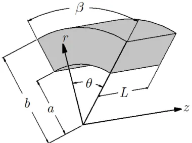
A functionally graded cylindrical panel with inner radius a, outer radius b, length L and span angle subjected to an internal impact loading is considered. The geometry and coordinate sys-tem of the cylindrical panel is shown in Figure 1.
Figure 1: Geometry of the cylindrical panel
2D-FGMs are usually made by continuous gradation of three or four different material phases
where one or two of them are ceramics and the others are metal alloy phases. Signi cant
develo-pments in fabrication and processing methods have made it possible to produce FGMs with two and three dimensional gradients using computer aided manufacturing processes. Therefore, the inner surface of the cylindrical panel is made of two distinct ceramics and the outer surface of two metals. The volume fractions of the constituent materials vary continuously through radial and axial directions in a predetermined composition profile. The volume fraction distribution function of each material can be expressed as:
1( , ) 1 1
r z
n n
c
r a z
V
b a
r z
L (1)
2( , ) 1
r z
n n
c
r a z
V
b a
r z
L (2)
1(, ) 1
r z
n n
m
r a z
r z V
Latin A m erican Journal of Solids and Structures 12 (2015) 205-225
2( , )
r z
n n
m
r a z
V
b a r
L
z (4)
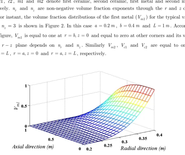
where c1, c2, m1 and m2 denote first ceramic, second ceramic, first metal and second metal, respectively. nr and nz are non-negative volume fraction exponents through the r and z direc-tions. For instant, the volume fraction distributions of the first metal (Vm1) for the typical values of nr nz 3 is shown in Figure 2. In this case a 0.2m, b 0.4m and L 1m. According
to this figure, Vm1 is equal to one at r b z, 0 and equal to zero at other corners and its
varia-tion in r z plane depends on nr and nz. Similarly Vm2, Vc1 and Vc2 are equal to one at ,
r b z L, r a z, 0 and r a z, L, respectively.
Figure 2: Volume fraction distribution of m1 with nr nz 3
Material properties at each point can be obtained by using the linear rule of mixtures, therefore the material property (R) such as modulus of elasticity and mass density in the 2D-FG
cylindri-cal panel is determined by linear combination of volume fractions and material properties of the basic materials as:
1 1 2 2 1 1 2 2 cVc cVc mVm mVm
R R R R R (5)
Accordingly, the cylindrical panel is pure c1, c2, m1 and m2 at r a z, 0, r a z, L,
, 0
r b z and r b z, L, respectively and the variation of desired material property depends
on the volume fraction distributions of the constituents in which the volume fractions depends on
r
n and nz. For example, the variation of a material property such as modulus of elasticity based
Latin A m erican Journal of Solids and Structures 12 (2015) 205-225
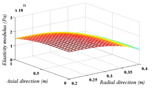
be seen from this figure, the elastic modulus is equal to Ec1, Ec2, Em1 and Em2 at r a z, 0,
,
r a z L, r b z, 0 and r b z, L, respectively and varies in r z plane based on Eq.
(5). The volume fractions in Eqs. (1-4) reduce to the conventional 1D-FGMs for nz 0 and in this case, the material properties vary only through the thickness direction. The basic consti-tuents of the 2D-FG cylindrical panel are presented in Table 1. It should be noted that Poisson’s ratio is assumed to be a constant value of 0.3. This assumption is reasonable because of the small
differences between the Poisson’s ratios of basic materials.
Figure 3: Distribution of elasticity modulus with nr nz 3
Constituents M aterial E GPa( ) (kg m3)
1
m Ti6A14V 105.7 4429
2
m Al 1,100 70 2707
1
c MnO 193 5026
2
c ZrO2 151 3000
Table 1: Basic constituents of the 2D-FG cylindrical panel
2.2 Governing Equations
Neglecting body forces, the equations of motion in cylindrical coordinates are obtained as:
2
2 1
( , )
r r rz r u
r r z r r z t (6-1)
2
2 ( , ) 2
1
r z r v
Latin A m erican Journal of Solids and Structures 12 (2015) 205-225
2
2 , 1
( )
rz z z rz w
r r z r r z t (6-3)
where u, v and w are radial, circumferential and axial components of displacement, respectively and is the mass density that depends on r and z coordinates.
The stress-strain relations from the Hook’s law in the matrix form are as:
D (7)
where the stress and strain components and the coefficients of elasticity D, are as the following
relations:
{ }T
r z z rz r (8)
{r z z rz r }T (9)
1 0 0 0
1 0 0 0
1 0 0 0
1 2
0 0 0 0 0
2
(1 )(1 2 )
1 2
0 0 0 0 0
2
1 2
0 0 0 0 0
( , )
2 r
E z
D (10)
where denotes the Poisson’s ratio and Eis the Young’s modulus of elasticity that depends on r
and z coordinates.
The strain-displacement equations based on the theory of linear elasticity in cylindrical coordi-nate are:
1 ,
r z
u v w
r z r
1
, rz
v u w
u
r z r
1 ,
z r
w u v v
z r r r
(11)
and in the matrix form are as:
Latin A m erican Journal of Solids and Structures 12 (2015) 205-225
where U is the displacements vector and is a matrix containing partial differentiating equa-tions as:
{u v w}T
U (13)
1 0 0 1
0 0 0
0 1
0
1 0 1
T
r z
z r
z r
r r
r r
r
(14)
The cylindrical panel is clamped on its two end edges and it is subjected to internal pressure that is a function of time. Therefore, the boundary conditions are as:
0, 0
z L
U (15)
The internal pressure function p tr( ) is an arbitrary function that will be presented later.
2.3 Graded finite element modeling
In order to solve the governing equations the graded finite element method is used. In this met-hod, in addition to displacement field, the heterogeneity of the material properties of the FGM may also be determined based on their nodal values. In this regard, shape functions similar to those of the displacement field may be used. This procedure can be used even for multi-directional functionally graded materials. Therefore, a graded finite element method (GFEM) is used to effectively trace smooth variations of the material properties at the element level. Using the graded elements for modeling of gradation of the material leads to more accurate results than dividing the solution domain into homogenous elements.
The cylindrical panel is divided into a number of 8–node linear elements. For element ( )e , the displacements in three directions are approximated as follow:
( )e ( )e
U (16)
where is the matrix of linear shape functions in cylindrical coordinate and ( )e is the nodal displacement vector of the element that are as:
8
8
8
(17)
1 1 1 8
( )
8 8
{ }T
e U V W U V W
(18)
Latin A m erican Journal of Solids and Structures 12 (2015) 205-225 To treat the material inhomogeneity by using the GFEM, it may be written:
8 (
1 )
i e
i i
(19)
where ( )e is the material property of the element.
Substituting Eq. (16) in Eq. (12) gives the strain matrix of element ( )e as:
( )e B ( )e (20)
where:
( )e
B (21)
Now by using Hamilton’s principal and Rayleigh-Ritz energy formulation, the GFEM is imposed and finally the mass, stiffness and force matrices are obtained as following:
2
1
T W 0
t
t
dt
(22)
where , T and W are potential energy, kinetic energy and virtual work done by surface
tracti-ons, respectively. These functions and their variations are:
1 2
T
V
dV (23)
T
V
dV (24)
1 T
2
T
V
dV
U U (25)
T T
V
dV
U U
(26)
W T
A
dA
U P
(27)
W T
A
dA
U P
(28)
where V and A are the volume and area of the domain under consideration and P is the vector
of surface traction and in the case of internal pressure is as:
{ 0 0}T
r p
Latin A m erican Journal of Solids and Structures 12 (2015) 205-225
Substituting Eqs. (23-28) in Hamilton’s Principal, applying side conditions 1 2,
0 t t
U and using
part integration:
T T T
V V A
dV U UdV P UdA
(30)
For each element, by imposing Eqs. (7, 16 and 20) into Eq. (30), it can be achieved:
( ) ( ) ( ) ( )
( )
T T
T
e T e T
V T e
e
A V
e
dV dV
dA
B DB
P
(31)
Since ( )eT
is the variation of the nodal displacements and is arbitrary, it can be omitted from Eq. (31), thus this equation can be written as:
( ) ( )e e ( ) ( )e e ( )e
M K F (32)
where the characteristic matrices are defined as:
( )e T
V
dV M
(33)
( )e T
V
dV
K B DB
(34)
( )e T
A
dA
F P
(35)
As D and are not constant, for obtaining the characteristic matrices for each element,
numeri-cal integration should be applied.
Now by assembling the element matrices and imposing the boundary conditions, the global equations of motion for the 2D-FG cylindrical panel can be written as:
M K F (36)
Once the nite element equations are determined, for free vibration analysis where the force ma-trix (F) is zero, by substituting ei t ( is the natural frequency) into Eq. (36), an eigen value problem would be obtained that can be solved using standard eigen value extraction proce-dures. Also, in the case of transient analysis, the Newmark direct integration method with suita-ble time steps is utilized to solve the equations. Newmark integration parameters are taken as (Zienkiewicz and Taylor, 2005):
1 2, 1 4
Latin A m erican Journal of Solids and Structures 12 (2015) 205-225 which lead to a constant average acceleration. This choice of parameters corresponds to a trape-zoidal rule which is unconditionally stable in linear analyzes.
3 NUMERICAL RESULTS AND DISCUSSION 3.1 Validation
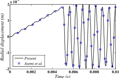
To validate the transient analysis of the current work, the data of an FG thick hollow cylinder under internal impact loading can be used (Asemi et al., 2011). Material distribution is assumed to be as 1D-FGM and it varies in radial direction with a power law function. In order to validate the results of this paper with the results of the present study, the span angel of the panel should be taken 2 to become a hollow cylinder, nz is taken zero, a = 1 m, b = 1.5 m, L = 1 m,
2 70
m
E GPa, 3
2 2707
m kg m , Ec2 380GPa, c2 3800kg m3 and the internal loading
function is assumed to be as:
0 0.005
( )
0 0.005
r
P t t s
p t
t s (38)
where P0 is 4GPa s. The comparison of the radial displacement at r 1.25m and z 0.5m
for nr 0.5 with the published data is shown in Figure 4 and a good agreement between these
two results is observed.
Figure 4: Time history of the radial displacement at r 1.25m
and z 0.5m for nr 0.5 compared with (Asemi et al., 2011)
Also, in order to validate the free vibration analysis of this study, the data of an FG curved panel can be used (Zahedinejad, 2010). The material properties are assumed to be varied from ceramic (
380 c
E GPa, c 3800kg m3) at inner radius to metal (Em 70GPa, m 2702kg m3) at 0 0.002 0.004 0.006 0.008 0.01
-2 -1 0 1 2x 10
-4
Time (s)
Ra
d
ia
l
d
isp
la
ce
m
en
t
(m
)
Latin A m erican Journal of Solids and Structures 12 (2015) 205-225
outer radius with a power law function. The boundary conditions are simply supported in four edges and the geometry is defined as:
0.75 , 1
1.25 , 1
a m L m
b m rad (39)
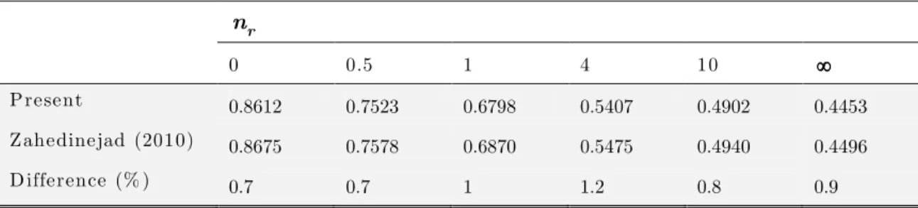
The comparison of fundamental frequency parameter ( (b a) c Ec ) with the published
results for different power law exponents is made in Table 2. According to this table, a closed agreement between the present results and those obtained from Zahedinejad (2010) is observed.
r
n
0 0.5 1 4 10
Present 0.8612 0.7523 0.6798 0.5407 0.4902 0.4453
Zahedinejad (2010) 0.8675 0.7578 0.6870 0.5475 0.4940 0.4496
D ifference (% ) 0.7 0.7 1 1.2 0.8 0.9
Table 2: The fundamental frequency parameter for FG cylindrical panel with four edges simply supported compared with (Zahedinejad, 2010)
3.3 Numerical Results
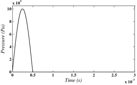
Consider a 2D-FG cylindrical panel with inner radius a = 0.2 m, outer radius b = 0.4 m and len-gth of L = 0.5 m. The panel is clamped at z 0,L and subjected to an impact loading at its inner surface. Constituent materials are two distinct ceramics and two distinct metals described in Table 1. The Poisson’s ratio is taken as a constant value of 0.3 and the loading function is assumed to be as:
0 0 0
0
sin( )
( ) 0 r
P t t t t
p t
t t (40)
where P0 and t0 are loading constants that are assumed to be as 107 Pa and 5 10 4 s,
respec-tively. Variation of the internal pressure with time is displayed in Figure 5. According to this figure, the cylindrical panel is excited by unloading in 4
0 5 10
t s. It is obvious that after the
Latin A m erican Journal of Solids and Structures 12 (2015) 205-225 Figure 5: Variation of internal pressure (pr) with time.
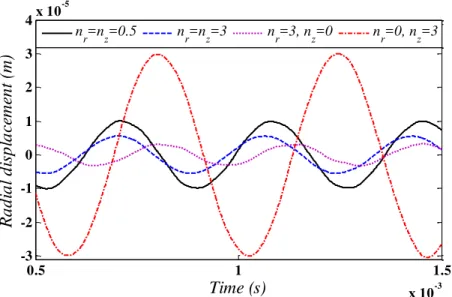
Figures 6 and 7 show the time history of radial displacement at r 0.3m, 30 , z 0.25m
and r 0.35m, 15 , z 0.125m, respectively after the unloading for different values of the
power law exponents. The span angle of the cylindrical panel is assumed to be 3. These
figures denote that the maximum amplitude of vibration belongs to the panel with power law exponents of nr 0, nz 3. In this case the cylinder is made of first and second metal and the
material distribution vary through the axial direction only. Also it can be seen from this figures that the minimum amplitude of vibration is for nr 3, nz 3.
Figure 6: Time history of the radial displacement at r 0.3m, 30 ,
0.25
z m with 3 for different values of nr and nz
0 0.5 1 1.5 2 2.5 3
x 10-3 0
2 4 6 8 10
x 106
Time (s)
Pre
ss
u
re
(
Pa
)
0.5 1 1.5
x 10-3 -4
-2 0 2 4 6
x 10-5
Time (s)
Ra
d
ia
l
d
isp
la
ce
m
en
t
(m
)
n
Latin A m erican Journal of Solids and Structures 12 (2015) 205-225
Figure 7: Time history of the radial displacement at r 0.35m,
15 , z 0.125m with 3 for different values of nr and nz
The time history of circumferential displacement at r 0.25m, 45 , z 0.375m for a
cy-lindrical panel with 3 after the unloading for different values of power law exponent is
demonstrated in Figure 8. According to this figure, due to asymmetry of geometry, the circumfe-rential displacement cannot be neglected. These results show how the time histories of displace-ments field are affected by the variation of volume fraction of constituent materials in two direc-tions.
Figure 8: Time history of the circumferential displacement at r 0.25m,
45 , z 0.375m with 3 for different values of nr and nz
0.5 1 1.5
x 10-3 -3
-2 -1 0 1 2 3 4x 10
-5
Time (s)
Ra
d
ia
l
d
isp
la
ce
m
en
t
(m
)
n
r=nz=0.5 nr=nz=3 nr=3, nz=0 nr=0, nz=3
0.5 1 1.5
x 10-3 -5
0 5 10
x 10-6
Time (s)
C
irc
u
m
fe
re
n
ti
a
l
d
isp
la
ce
m
en
t
(m
)
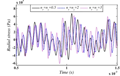
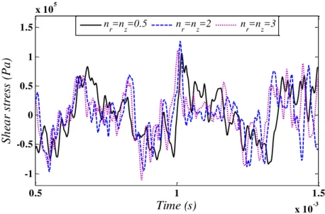
nLatin A m erican Journal of Solids and Structures 12 (2015) 205-225 The time history of radial, circumferential, shear ( r ) and axial stresses, respectively at
0.3
r m, 30 , z 0.25m for a cylindrical panel with 3 after the unloading for
dif-ferent values of power law exponent are shown in Figures 9-12. It is obvious that variation of stresses is highly dependent of power law exponents. Also, as the same as circumferential displa-cement, the shear stress ( r ) cannot be neglected in asymmetric geometries.
Figure 9: Time history of the radial stress at r 0.3m, 30 ,
0.25
z m with 3 for different values of nr and nz
Figure 10: Time history of the circumferential stress at r 0.3m,
30 , z 0.25m with 3 for different values of nr and nz
0.5 1 1.5
x 10-3 -6
-4 -2 0 2 4 6 8
x 105
Time (s)
Ra
d
ia
l
st
re
ss
(
Pa
)
n
r=nz=0.5 nr=nz=2 nr=nz=3
0.5 1 1.5
x 10-3 -6
-4 -2 0 2 4 6 8x 10
5
Time (s)
C
irc
u
m
fe
re
n
ti
a
l
st
re
ss
(
Pa
)
n
Latin A m erican Journal of Solids and Structures 12 (2015) 205-225
Figure 11: Time history of the shear stress ( r ) at r 0.3m,
30 , z 0.25m with 3 for different values of nr and nz
Figure 12: Time history of the axial stress at r 0.3m, 30 ,
0.25
z m with 3 for different values of nr and nz
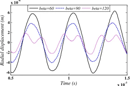
Figures 13 and 14 illustrate the time history of the radial displacement and stress at r 0.3m,
30 , z 0.25m, respectively after the unloading for different values of with power law
exponents of nr 2, nz 1. It can be seen that by increasing the span angle of cylindrical pa-nel, the amplitude of radial displacement is decreased while the frequency of vibration is in-creased.
0.5 1 1.5
x 10-3 -1
-0.5 0 0.5 1 1.5
x 105
Time (s)
S
h
ea
r
st
re
ss
(
Pa
)
n
r=nz=0.5 nr=nz=2 nr=nz=3
0.5 1 1.5
x 10-3 -1
-0.5 0 0.5 1
x 106
Time (s)
Ax
ia
l
st
re
ss
(
Pa
)
n
Latin A m erican Journal of Solids and Structures 12 (2015) 205-225 Figure 13: Time history of the radial displacement at r 0.3m,
30 , z 0.25m with nr 2, nz 1 for different values of
Figure 14: Time history of the radial stress at r 0.3m, 30 ,
0.25
z m with nr 2, nz 1 for different values of
From the time history of the radial stress, it is possible to extract the approximate radial stress wave propagation velocity. Thus, by computing the time taken by the wave to cover the whole of the cylinder immediately after the loading, the approximate radial stress wave propagation veloci-ties can be estimated. Table 3 shows the comparison of radial stress wave propagation velocity with analytical results (Jones, 1997) for cylindrical panels made of different homogenous mate-rials. As it is obvious from this table, the obtained results have a good compatibility with
analyti-0.5 1 1.5
x 10-3 -6
-4 -2 0 2 4 6
x 10-6
Time (s)
Ra
d
ia
l
d
isp
la
ce
m
en
t
(m
)
beta=60 beta=90 beta=120
5 6 7 8 9 10
x 10-4 -6
-4 -2 0 2 4 6 8x 10
5
Time (s)
Ra
d
ia
l
st
re
ss
(
Pa
)
Latin A m erican Journal of Solids and Structures 12 (2015) 205-225
cal ones. Table 4 illustrates the variation of radial stress wave propagation velocity at different heights of cylindrical panel for different values of power law exponents. This table denotes that velocity of radial stress wave is strongly affected by the power law exponents. Also due to the variation of material properties through the axial direction, the velocity of radial stress wave at different heights of the cylindrical panel is changing.
M aterial Present (m s) A nalytical (m s) D ifference (% )
=0, =
r z
n n m1 5714 5668 0.8
= =0
r z
n n m2 5970 5900 1.2
= =
r z
n n c1 7272 7189.8 1.1
0
= , =
r z
n n c2 8163 8231.4 0.8
Table 3: Comparison of radial stress wave propagation velocity of homogenous cylindrical panel with analytical results (Jones, 1997)
4
z L z L2 z 3L 4
= = 0.5
r z
n n 6504 6612 6723
= =3
r z
n n 6897 6957 7143
=3, =0
r z
n n 7619 7619 7619
=0, =3
r z
n n 5797 5839 5882
Table 4: Velocity of radial stress wave propagation at different heights of cylindrical panel for different values of power law exponents
Now by introducing the normalized natural frequency as:
1 1
10 b m Em (41)
the fundamental normalized natural frequency of 2D-FG cylindrical panel for different values of the power law exponents and span angles are presented.
The effect of power law exponents on the fundamental normalized natural frequency ( ) of 2D-FG cylindrical panel with 3 is shown in Table 5. As it can be seen, by increasing nr
and decreasing nz the fundamental normalized natural frequency increases.
0
r
n = nr =1 nr =3
0
z
n nz1 nz3 nz0 nz1 nz 3 nz0 nz1 nz3
1.9871 1.9354 1.8639 2.3913 2.2569 2.1522 2.5700 2.3984 2.2786
Latin A m erican Journal of Solids and Structures 12 (2015) 205-225 Table 6 illustrates the effect of span angle of the 2D-FG cylindrical panel on the fundumental normalized natural frequency with nr 2 and nz 1. It is obvious that by increasing the span
angle of cylindrical panel, the fundamental natural frequency growths.
12 6 4 3 2 3
1.5785 2.1792 2.3481 2.3515 2.3817 2.4318
Table 6: Fundamental normalized natural frequency for different values of span angle with nr 2, nz 1
Results denote that the distribution of displacements and stresses and natural frequencies are strongly affected by the power law exponents and the span angle of cylindrical panel. As it can be seen from the results, the distribution of stresses has continuous variations due to using graded elements. The use of GFEM has several benefits over the use of conventional FEM in the dyna-mic and wave propagation analyses. In conventional FEM, the boundary of homogenous elements of an inhomogeneous material acts as discrete boundaries for the stress waves. These boundaries cause artificial wave reflections and have a cumulative effect on the magnitude and speed of pagating stress waves. In addition, these inaccuracies will be more significant in 2D-FGM pro-blems. Therefore, by using graded finite element in which the material property is graded conti-nuously through the elements, accuracy can be improved without refining the mesh size.
4 CONCLUSIONS
The main purpose of the present paper is to study the 3D transient and free vibrational beha-viour of 2D-FG cylindrical panels. The 3D graded finite element method and Rayleigh-Ritz energy formulation is applied. The proposed method is validated by the result of a 1D-FG thick hollow cylinder under the impact loading and an FG curved panel which are extracted from pu-blished literature. The comparisons between the results show that the present method has a good agreement with the existing results. Different types of displacement and stress in three directions and fundamental normalized natural frequency are presented for various values of power law ex-ponents and span angle of cylindrical panel. Also, velocity of radial stress wave propagation for different power law exponents is obtained. Results denote that the maximum stresses, stress dis-tribution, natural frequency and velocities of radial stress wave can be controlled by the variation of material properties in two directions. Based on the achieved results, 2D-FGMs have powerful potentials for designing and optimizing structures under multi-functional requirements.
References
Latin A m erican Journal of Solids and Structures 12 (2015) 205-225
Asemi, K., Akhlaghi, M., Salehi, M. (2011). Dynamic analysis of thick short length FGM cylinders. Meccanica 47:1441-1453.
Asgari, M., Akhlaghi, M., Hosseini, S.M. (2009). Dynamic analysis of two-dimensional functionally graded thick hollow cylinder with nite length under impact loading. Acta Mechanica 208:163-180.
Asgari, M., Akhlaghi, M. (2010) Transient thermal stresses in two-dimensional functionally graded thick hollow cylinder with nite length. Archive of Applied Mechanics 80:353-376.
Ashrafi, H., Asemi, K., Shariyat, M., Salehi, M. (2012) Two–dimensional modeling of heterogeneous structures using graded finite element and boundary element methods. Meccanica 48:663-680.
Bahtui, A., Eslami, M.R. (2007) Coupled thermoelasticity of functionally graded cylindrical shells. Mechanics Research Communications 34:1-18.
Birman, V., Byrd, L. (2007) Modeling and analysis of functionally graded materials and structures. Applied Mechanics Reviews 60:195-216.
Bodaghi, M., Shakeri, M. (2012) An analytical approach for free vibration and transient response of functionally graded piezoelectric cylindrical panels subjected to impulsive loads. Composite Structures 94:1721-1735.
Davar, A., Khalili, S.M.R., Malekzadeh Fard, K. (2013) Dynamic response of functionally graded circular cylin-drical shells subjected to radial impulse load. International Journal of Mechanics and Materials in Design 9:65-81.
Ebrahimi, M.J., Najafizadeh, M.M. (2014) Free vibration analysis of two-dimensional functionally graded cylin-drical shells. Applied Mathematical Modelling 38: 308–324.
Hosseini, M., Akhlaghi, M., Shakeri, M. (2007) Dynamic response and radial wave propagations of functionally graded thick hollow cylinder. International Journal for Computer-Aided Engineering and Software 24:288-303. Jha, D.K., Kant, T., Singh, R.K. (2013) A critical review of recent research on functionally graded plates. Com-posite Structures 96:833–849.
Jones, N. (1997) Structural Impact. University Press, Cambridge.
Kim, J.H., Paulino, G.H. (2002) Isoparametric graded finite elements for nonhomogeneous isotropic and orthotropic materials. Journal of Applied Mechanics 69:502-514.
Koizumi, M. (1993) The concept of FGM. Ceramic Transactions, Functionally Gradient Materials 34:3-10. Malekzadeh, P., Monajjemzadeh, S.M. (2013) Dynamic response of functionally graded plates in thermal envi-ronment under moving load. Composites Part B: Engineering 45:1521-1533.
Nemat-Alla, M. (2009) Reduction of thermal stresses by composition optimization of two-dimensional functiona-lly graded materials. Acta Mechanica 208:147-161.
Qian, L.F., Batra, R.C, Chen, L.M. (2004) Static and dynamic deformations of thick functionally graded elastic plates by using higher-order shear and normal deformable plate theory and meshless local Petrov–Galerkin method. Composites Part B: Engineering 35:685-697.
Qu, Y., Long, X., Yuan, G., Meng, G. (2013) A uni ed formulation for vibration analysis of functionally graded shells of revolution with arbitrary boundary conditions. Composites: Part B 50: 381–402.
Shakeri, M., Akhlaghi, M., Hosseini, S.M. (2006) Vibration and radial wave propagation velocity in functionally graded thick hollow cylinder. Composite Structures 76:174-181.
Shao, Z.S., Fan, L.F., Wang, T.J. (2004) Analytical solutions of stresses in functionally graded circular hollow cylinder with nite length. Key Engineering Materials 261–263:651-656.
Shao, Z.S. (2005) Mechanical and thermal stresses of a functionally graded circular hollow cylinder with nite length. International Journal of Pressure Vessels and Piping 82:155-163.
Latin A m erican Journal of Solids and Structures 12 (2015) 205-225 Uymaz, B., Aydogdu, M. Three-Dimensional Vibration Analyses of Functionally Graded Plates under Various Boundary Conditions. Journal of Reinforce Plastic Composites 26:1847–1863.
Wang, X., Sudak, L.J. (2008) Three-dimensional analysis of multi-layered functionally graded anisotropic cy-lindrical panel under thermomechanical loading. Mechanics of Materials 40:235-254.
Yas, M.H., Sobhani Aragh B. (2010) Three-dimensional analysis for thermoelastic response of functionally graded fiber reinforced cylindrical panel. Composite Structures 92:2391-2399.
Zafarmand, H., Kadkhodayan, M. (2014) Three-dimensional static analysis of thick functionally graded plates using graded finite element method. Proceedings of the Institution of Mechanical Engineers, Part C: Journal of Mechanical Engineering Science 228:1275-1285.
Zafarmand, H., Hassani, B. (2014) Analysis of two-dimensional functionally graded rotating disks with variable thickness. Acta Mechanica 225:453–464.
Zahedinejad, P., Malekzadeh, P., Farid, M., Karami, G. (2010) A semi-analytical three-dimensional free vibra-tion analysis of funcvibra-tionally graded curved panels. Internavibra-tional Journal of Pressure Vessels and Piping 87:470-480.
Zienkiewicz, O.C., Taylor, R.L. (2005) The finite element method for solid and structural mechanics, 6th edn. Elsevier Butterworth-Heinemann, Oxford.
Appendix
The components of are:
1 i
V
X (A1)
where V is the volume of each element that is:
1 1 1 1 1 1 1 1 1 1 1 1
2 2 2 2 2 2 2 2 2 2 2 2
3 3 3 3 3 3 3 3 3 3 3 3
4 4 4 4 4 4 4 4 4 4 4 4
5 5 5 5 5 5 5 5 5 5 5 5
6 6 6 6 6 6 6 6 6 6 6 6
7 7 7 7 7 7 7 7 7 7 7 7
8 8 8 8 8 8 8 8 8 8 8
1 1 1 1 1 1 1 1 V
8
(A2)
and:
( 1)i j
ij ij
Α (A3)
{1, , , , , , , }T
X (A4)
in which:
cos , sin ,
r r z (A5)
cos , sin ,
i ri i i ri i i zi (A6)
where ri, i and zi are nodal coordinates and Αij is obtained from eliminating the i th
row and jth