Investigation of dynamic instability of three plates switch under step
DC voltage actuation using modified couple stress theory
Abstract
In this paper dynamical instability of three-layer micro-switch under DC voltage actuation has been studied. Recent studies have used the classical beam theory while leaving out the length scale parameter. In this paper dynamic behavior of the switch has been investigated based on couple stress theory and considering the length scale parameter. To this end, gov-erning dynamic equation of the micro switch has been extracted and pre-sented. Considering the nonlinearity of governing equation due to the ex-istence of electrostatic force, Galerkin method has been implemented to overcome this nonlinearity and solve the mentioned equation and obtain the dynamic response. Dynamic response of micro switch has been investi-gated with and without considering the damping effects. Variation of dy-namic pull-in voltage versus micro beam length and primary gap between micro beam and stationary electrodes have been studied using couple stress and classic beam theory and obtained results have been compared to each other. Also dependency of dynamic pull-in voltage to damping factor has been studied with considering two theories. Furthermore switching time of micro switch have been determined and compared using couple stress and classic beam theories.
Keywords
micro switch; dynamic instability; electrostatic; couple stress theory; len-gth scale parameter
1 INTRODUCTION
Nowadays micro electro mechanical devices have shown remarkable significance in various industries such as automation, military, medical, telecom. This issue is because of significant advantages of these structures such as small size, low energy consumption, high performance, low manufacturing costs and feasibility for batch fabri-cation. Simulating the mechanical behavior of these devices, particularly their static and dynamic behavior, is required for design and manufacturing purposes. Therefore, electrostatically actuated MEM/NEM devices such as, micro switches [1, 2] micro-mirrors [3, 4], nano-switches [5, 6], nano-tweezers [7, 8], micro capacitors [9-11], sensors [12, 13], resonators [14, 15] and oscillators [16, 17] are widely designed, fabricated, used and analyzed.
The majority of the micro structures perform using electrostatic actuation. The nature of this actuation is nonlinear which results in the nonlinearity of the governing equations. Presence of such nonlinearity along with length scale parameter cause difficulty in analysis with simulation soft wares and may result in deviation of ob-tained results. Therefore theoretical analysis may be considered as firm technique to examination of mechanical behavior. Precise modeling of micro switch is necessary to obtain accurate behavior of the structures. Length scale parameter is an important parameter which must be considered for analysis of mechanical behavior of mi-cro structures. This parameter is an inherent characteristic of movable part of mimi-cro structure (mimi-cro beam or micro plate), and if it is less than specific limit, its effects is exposed. Application of classic beam theory (classic elasticity theory) for micro structures with non-negligible length scale parameter may result in inaccurate results. So considering the length scale parameter and application of couple stress theory instead of classic beam theory is an essential issue in the case of mechanical analysis of micro structures. Numerous researches have been done in the case of static and dynamic stability analysis of micro switches without considering this effect [18-26]. Some works have devoted to analysis of static and dynamic behavior of micro and nano structures considering the
Karamat Malekzadeh Farda* Amin Gharechahib
Niloofar Malekzadeh Fardb Hamed Mobkib
a Malek Ashtar University of Technology, Tehran,
Iran. E-mail: [email protected]
b Department of biomedical engineering, Islamic
Azad Uni-versitty, Science and reaserch branch, Tehran, Iran. E-mail:
[email protected], [email protected], [email protected]
*Corresponding Author
http://dx.doi.org/10.1590/1679-78254636
Received: October 31, 2017
In Revised Form: November 03, 2017 Accepted: March 20, 2018
switches using strain gradient and couple stress theory have been studied in refs. [5, 6, 28, 29]. Keivani et al. [7] investigated the instability analysis of nanotweezers using couple stress theory. Rashvand et al. [30-32] studied size-dependent behavior of circular and rectangular micro-plates.
The dispersion forces play an important role in the instability behavior of nano structures. Although the ef-fects of these forces can be neglected in the modeling of static and dynamic behavior of micro structures. In nano-scale, Tadi Beni et al. [19] have studied pull-in instability in a torsional nano-actuator considering Casimir force. Vakili et al. [33], Koochi et al. [20] and Soroush et al. [22] have studied instability of nano-beams subjected to elec-trostatic force and considering van der Waals force. Koochi et al. investigated pull-in instability of carbon nano-tube based actuator under the Coulomb force and considering van der Waals attraction [24]. Dequesnes et al. [34, 35] have studied the pull-in phenomena and pull-in voltage of a carbon-based nano-electromechanical switch.
Three layer micro switch is a type of micro structure, in which micro-beam/micro-plate is suspended be-tween two stationary plates. Recently some investigations have been accomplished in the case of static and dy-namic stability analysis of these switches. Comprehensive stability analysis of three plate micro switch subjected to electrostatic force has been presented in ref. [36]. Azizi et al. [37] studied bifurcation Behavior of a Capacitive three layer microswitch. Mobki et al. [38] designed and analyzed a new micromachined tunable three layer capac-itor with extended tenability. Azimloo et al. [39] Shah-Mohammadi-Azar [40] presented Angular Velocity Sensors based three layer switch and studied their pull-in behavior. However most of the related researches are based on overlooking of length scale parameter.
With regard to the importance of dynamic analysis of these switches and considering this effect, this paper is devoted to study the dynamic behavior, instability and pull-in voltage of three layer micro switch with consider-ing length scale parameter and usconsider-ing couple stress theory instead of classic beam theory. Furthermore, the im-portance of considering or neglecting this effect has been discussed. For this aim, the governing dynamic equation of the micro-switch has been presented. Moreover, due to the nonlinearity of this equation, which is a result of the existence of electro static force, Galerkin method has been implemented for solving the governing equation. In the rest of the paper, the model description, mathematical model of micro switch, obtained results and supplemen-tary discussion for results are presented.
2 MODEL DESCRIPTION
In this section schematic view of studied micro-switch is illustrated in the coming section and the governing equations of the micro-switch will be extracted and presented. Figure 1(a) shows the schematic view of three layer micro switch, in which a micro beam is situated between two stationary electrodes. Initial distance of micro beam to upper and lower electrode is
G
0. Applied voltages ofV
1 andV
2 are induced from lower and upper elec-trode to micro beam. These voltages cause to attraction electrostatic force between micro beam and elecelec-trodes. If2 1
V V
, imposed electrostatic force from upper electrode prevails over imposed force from lower electrode and micro beam bends toward upper electrode and vice versa. IfV V
1
2, micro beam is settled in its initial place and does not move toward any electrodes. Figure 1(b) shows the cross section view of the micro switch.h
andb
indicate thickness and width of micro beam. Micro beam is considered as isotropic media with elastic modulus of
E
, density of
, length ofL
, cross moment inertia ofI
, cross section ofA
. Parameterp
denotes applied volt-ages ratio and equals with 2Figure 1: schematic view of three layer micro switch
3 MATHEMATICAL MODELING
The governing dynamic equation of the micro switch is obtained and presented in this section.
Based on the couple stress theory strain energy
U
of an isotropic material with linear elasticity behavior can be presented as [41]:
1
2
ij ij ij ij VU
m
dV
(1)where
V
is the occupied volume of the material. σ, ε, m and 𝜒 are stress, strain, derivative part of couple stress and symmetric part of curvature tensors. Based on the linear elasticity theory, mentioned tensors can be presented as:2
ij kk ij G ij
(2)
, ,
1
2
ij
u
i ju
j i
(3)2
2
ij ij
m
l G
(4)
, ,
1
2
ij i j j i
(5)In this equation 𝜆 and G are Lame constants, l is length scale parameter of material, u and 𝜃 are displacement and rotation vectors. Also correspondence of these vectors is as:
1
2
curl u
(6)Considering the x-z coordinate of Figure 1, which x axis coincide centroidal one; arrays of displacement vec-tors can be shown in the form of [42]:
, , 0 ,
,
u
z
x t v
w w x t
(7)Where u, v and w are components of displacement vectors in direction of x, y and z axes respectively. Also rotation angle (𝜓) can be obtained based on the classic beam theory:
,
w x t
x
For plane stress and infinitesimal displacement, the components of strain tensor can be achieved using of Eqs. (3), (7), and (8) as:
2 2 2 2 2 2
0
xx yy zzxy yz xz
u
z
w
x
x
w
z
x
w
z
x
(9)Based on Eqs. (6)-(8) following relations are accurate.
,
0
y
x y
w x t
x
(10)With substituting Eq. (10) into equation 5, arrays of symmetric curvature tensor can be presented as:
2 2,
1
2
0
xyxx yy zz xz yz
w x t
x
(11)Similarly the form of stress tensor components can be extracted by substituting of Eq. (9) into Eq. (2). 2
2
0
xx
yy zz xy xz yz
w
Ez
x
(12)Arrays of derivative part of couple stress tensor can be obtained by placing of Eq. (11) into Eq. (4): 2
2 2
0
xy
xx yy xz yz zz
w
m
Gl
x
m
m
m
m
m
(13)Strain energy U can be presented as equation 14, with substituting of Eqs. (9), (11), (12) and (13) into equa-tion 1.
2 2 2 2 0,
,
1
2
L x xyw x t
w x t
U
M
Y
dx
x
x
(14)Where
M
x and Yxy indicate resultant and couple moment and are as:x xx
xy xy
M
zdA
Y
m dA
(15)Kinetic energy also can be shown as Eq. (16):
20
,
1
2
L
w x t
T
A
dx
Virtual work of electrostatic force may be assumed as:
0,
,
L elecW
q
x t w x t dx
(17)Where
q
elec indicates induced electrostatic force to micro beam. Based on the Hamilton principal followingrelation is valid.
0
0
t
T U W dt
(18)Governing dynamic equation of micro beam based on the couple stress theory and taking into account the re-sidual stress and damping effects can be elicited and shown as:
2
4 2 24 2 r 2 elec
w
w
w
w
EI GAl
c
A
N
q
x
t
t
x
(19)Where
N
r
r
1
bh
is residual force, and
r and
are the biaxial effective residual force and Poisson'sratio [2]. Considering the above equation; it is obvious that bending rigidity of micro beam is composed from two terms of EI (bending rigidity based classic beam theory) and GAl2 (bending rigidity caused by considering of length scale parameter effects).
Electrostatic force per length of micro beam can be shown based on the reports of ref [36] as:
2 2
0 1 2
2 2
0 0
2
elec
b
V
V
q
G w
G w
(20)Where 12 2 1 2
0 8.854 10 C N m
is permittivity coefficient of vacuum. Governing equation of micro beam based on classic beam theory can be extracted by settingl
0
in Eq. (20).The governing dynamic equation of three layer micro-switch subjected to electrostatic force and considering length scale parameter of micro-beam are presented in this section. Due to the nonlinearity of term of electrostat-ic force, Galerkin method are implemented for dynamelectrostat-ic analysis of the melectrostat-icro-switch. This method is proper and reliable one for analysis of static and dynamic behavior of micro and nano-switches. The procedure of Galerkin implementation for solving the Eq. (19) will be extended in the next section.
4 NUMERICAL METHOD
In this section applied numerical approach for solving the Eq. (19) is presented. For this case dynamic dis-placement can be assumed as:
1
,
N i ii
w x t
q t
x
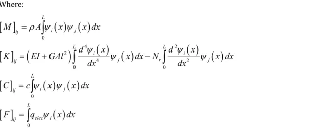
(21)Using Galerkin approximation method, the equation of dynamic response has been obtained as [43]:
M q
¨
C q
K q
F
Where:
0 4 2 2 4 2 0 0 0 0 L i j ij L L i ij r j
ij L i j ij L elec i ij
M
A
x
x dx
d
x
d
x
K
EI GAl
x dx N
x dx
dx
dx
C
c
x
x dx
F
q
x dx
(23)Where indicate the effective mass, stiffness, damping, and actuating force matrices respectively.
q t
can be obtained from above set of ordinary differential equations using an integration scheme.5 RESULTS AND DISCUSSION
5.1. Validation and Convergence of Numerical Method
This subsection deals with validation of numerical method. For this purpose obtained results of this paper have been compared with those obtained by Hung and Senturia [44]. The micro-switch specification are
149
E
Gpa
,
2330
kg
m
2 ,L
610
m
,b
40
m
,h
2.2
m
,G
0
2.3
m
,
r
3.7
MPa
, andp
0
.Calculated pull-in time for various values of applied voltages are shown in Figure 2. As can be seen in this figure, results of this paper are in good agreement with theoretical and experimental results.
Figure 2: Comparison of the pull-in time for various values of applied voltage
For more validation the obtained results of this paper are compared with those presented in ref [37]. The mi-cro-switch is a fixed-fixed one with
E
169
Gpa
,
2330
kg
m
2 ,L
600
m
,b
4
m
,h
2
m
,0
2
G
m
,
r
3.7
MPa
, andp
0.5
. The results convergence and comparison are shown in table 1. AsTable 1: Comparison of the pull-in voltage
Results of ref [37] This paper (N=1) This paper (N=2) This paper (N=3)
Pull-in voltage 10.07 10.12 10.11 10.11
5.2. Dynamic response of micro-switch
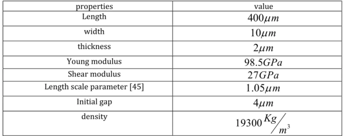
In this section obtained results of the dynamic instability of golden micro switch are presented. Physical and spatial properties of the micro switch are shown in table 2. The micro beam is a cantilever gold one.
Table 2: physical and geometrical properties of studied three layer golden micro switch
properties value
Length
400
m
width
10
m
thickness
2
m
Young modulus
98.5
GPa
Shear modulus
27
GPa
Length scale parameter [45]
1.05
m
Initial gap
4
m
density
3
19300
Kg
m
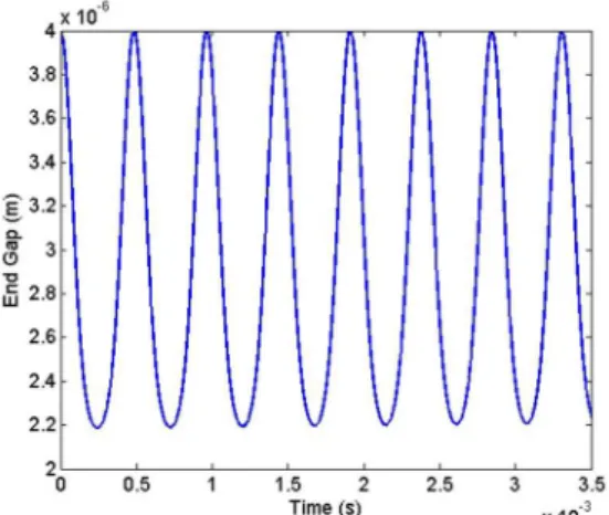
Variation of gap between end tip of micro beam and lower electrode versus to time (using couple stress the-ory) for applied voltage 10.44 V is depicted in Figure 3. As shown in this figure, with applying this voltage, micro beam oscillates and no instability occurs. Phase diagram relevant to this figure is shown in Figure 4. As shown in this figure, phase portrait of micro beam is a restricted oval-shaped environment, where asymmetry of this shape with respect to horizon axis is caused by nonlinear electrostatic force.
Figure 4: Velocity of end tip versus end gap under step DC voltage of
V
1
10.44
V
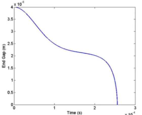
actuation, using couple stress theoryEnd gap versus time for applied voltage 10.45 is shown in Figure 5. As it can be observed in this figure, apply-ing of 10.45V results in instability and collision of micro beam to lower electrode. Minimal applied voltage (10.45V) which causes the instability of micro beam, is entitled as dynamic instability voltage or dynamic pull-in voltage. Phase portrait of Figure 5 is shown in Figure 6. As shown in this figure increasing of end gap cause the tendency of velocity to higher values. These magnitude (pull-in voltage) was obtained by trial and error. If the applied voltage causes to instability (stability) of micro-switch the mentioned voltage decrease (increase) as long as obtaining dynamic pull-in voltage.
Figure 5: End gap versus time under step DC voltage of
V
1
10.45
V
actuation, using couple stress theoryDynamic responses of micro beam to applied voltages 7.56V and 7.57V are drawn (using classic beam theory) and shown in Figure 7 and Figure 9 Related phase portraits are shown in Figure 8 and Figure 10 respectively. With comparing Figure 7 and Figure 9 it can be concluded that pull-in voltage of micro beam based on the classic beam theory is 7.57V. However, as mentioned before, using couple stress theory yields 10.45V for pull-in voltage. This remarkable difference between two magnitudes of pull-in voltage is because of considering and neglecting the effects of length scale parameter. Considering this effect, which causes the increase of bending rigidity of mi-cro beam and consequently, the dynamic pull-in voltage is increased too.
Figure 7: End gap versus time under step DC voltage of
V
1
7.56
V
actuation, using classic beam theoryFigure 8: Velocity of end tip versus end gap under step DC voltage of
V 7.56V
1
actuation, using classic beam theoryFigure 10: Velocity of end tip versus end gap under step DC voltage of
V
1
7.57
V
actuation, using classic beam theoryBased on the reported results of ref [2]
3 30 034 4
0 0
pull in classic
Eh G
EIG
V
L
b L
(24)Based on the couple stress theory and considering
EI GAL
2 as bending rigidity, the above equation may be presented as:
2
034 0
pull in couple
EI GAL G
V
b L
(25)So following equation can be presented as ratio of pull-in voltage obtained using couple stress and classic beam theory:
2
pull in couple
pull in classic
V
EI GAL
EI
V
(26)Based on the above relation mentioned ratio is about 1.381 for the studied micro-switch. As shown in Figure 6 and Figure 10 the ratio of pull-in voltages is
10.45 1.38
7.57
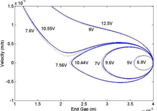
, where is conformable with Eq. (26).Figure 11: Phase portrait of golden micro beam subjected various applied voltages
Variation of pull-in voltage versus micro beam length and initial gap are shown in Figure 12 and Figure 13 respectively. As can be seen in these figures pull-in voltage decreases with increase of length and decrease of ini-tial gap. Although there are considerable differences between diagrams of couple stress and classic beam theories, these differences are more evident for low length and high gap. As can be seen in these figures for identical length or gap
pull in couple
1.38
pull in classic
V
V
. So
V
pull in
couple
V
pull in
classic
0.38
V
pull in
classic and it is proved that differenceof two obtained voltages is equal with
0.38
V
pull in classic
and with increase of
V
pull in classic
this difference is increased too. As shown in Figure 12 and Figure 13 with increase of gap and decrease of length,
V
pull in classic
is increased and by increasing of
V
pull in classic
, the difference of
V
pull in
couple
V
pull in
classic is increased too.Figure 12: Dynamic instable voltage versus length for golden micro beam
In the following part of this section, the instability of micro switch with considering damping effects are in-vestigated. Dynamic response of micro switch for applied voltages of 10.68V and 10.69V and
c
0.02
is shown in Figure 14. As shown in this figure applying of 10.68V causes the oscillation of micro beam and as a consequence of damping effects, oscillation amplitude decreases gradually. But for applied voltage 10.65V micro beam loses its stability and collapses on to lower electrode. As shown in Figure 5 pull-in voltage for undamped case is 10.45V, but for the case with damping coefficient ofc
0.02
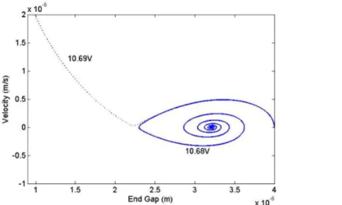
is 10.69V, where it indicates increase of damping effect leads to the increase of pull-in voltage. Relevant phase diagram of Figure 14 is depicted in Figure 15. As shown in this figure phase diagram for applied voltage of 10.68 is spiral-shaped where with time elapsing, velocity tend to zero.Figure14: End gap versus time, for damping coefficient
c
0.02
, using couple stress theoryFigure 15: Velocity of end tip versus end gap for damping coefficient
c
0.02
, using couple stress theory Dynamic response and phase portraits of the micro beam subjected to applied voltages 7.79V and 7.8V for0.02
c
are depicted in Figure 16 and Figure 17. From Figure 16, it can be concluded that pull-in voltage based on the classic beam theory is 7.8V. As mentioned before, as a consequence of increase of damping effect, pull-in voltage increase too.Figure 17: Velocity of end tip versus end gap for damping coefficient
c
0.02
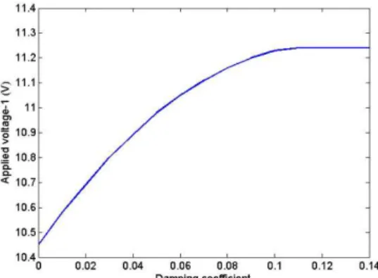
, using classic beam theoryVariation of pull-in voltage versus damping coefficient was extracted and depicted in Figure 18 and Figure 19. As shown in these figures for c <1.8 pull in voltage depends on the damping ratio and with increasing this ratio the pull-in voltage increases too. But above this level (for c >1.8), pull-in voltage remains constant and can be regarded as damping-independent.
Figure 18: variation of dynamic instable voltage versus damping coefficient using couple stress theory
Figure 19: variation of dynamic instable voltage versus damping coefficient using classic beam theory
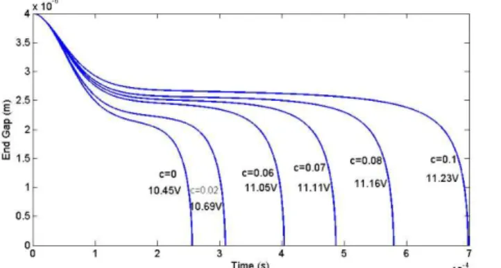
Figure 20: Instability diagrams of micro beam for various magnitude of damping coefficient, using couple stress theory
Figure 21: Instability diagrams of micro beam for various magnitude of damping coefficient, using classic beam theory
6 CONCLUSION
Dynamic instability of three layer micro switch was studied using the classic beam and couple stress (with considering length scale parameter) theories. For this reason governing dynamic equation of micro switch was obtained with and without considering the length scale parameter. Considering the nonlinearity of governing equation, Galerkin method was implemented to solve the governing equation. The applied numerical method was validated with previous experimental and numerical methods. The validation results showed good ability of Ga-lerkin method for solving the governing dynamic equation. Dynamic behavior and pull-in voltage of the micro switch were investigated with considering the damping effects and using two mentioned theories. The obtained results showed that the calculated pull-in voltage by couple stress theory is higher than the one calculated by classic beam theory. Also it was shown that the ratio of pull-in voltages based on the couple stress theory to clas-sic beam theory is a specific value. Furthermore, the dependency of pull-in voltage to initial gap and micro-beam length were studied and it was shown that with increase of initial gap and decrease of micro-beam length, the effect of considering of length scale parameter gets more obvious. Obtained results indicate remarkable difference between results of classic beam and couple stress theories, where obtained pull-in voltage based on the couple stress theory is higher than the obtained one using classic beam theory. Moreover, the variation of pull-in voltage and pull-in time with respect to damping coefficient were investigated. Results of dynamic case with considering damping effects confirmed that with increasing damping coefficient, the amplitude of oscillation decreases. Ac-quired results in this case showed that increase of damping coefficient results in increase of pull-in voltage as well as pull-in time.
REFERENCES
[1] W. Tian, Z. Chen, (2015), “Analysis of bistable inductive micro-switch based on surface micro size effect”, Ap-plied Surface Science, 334(15), 32-39.
[3] M. Taghizadeh, H. Mobki, (2014), “Bifurcation analysis of torsional micromirror actuated by electrostatic forc-es”, Archives of Mechanics, 66(2), 95-111.
[4] Y. Wang, K. Kumar, L. Wang, X. Zhang, (2012), “Monolithic integration of binary-phase fresnel zone plate objec-tives on 2-axis scanning micromirrors for compact microscopes”, Optics express, 20(6), 6657-6668.
[5] A. Koochi, H. Hosseini-Toudeshky, (2015), “Coupled effect of surface energy and size effect on the static and dynamic pull-in instability of narrow nano-switches”, International Journal of Applied Mechanics, 7(04), p.1550064.
[6] A. Kanani, A. Koochi, M. Farahani, E. Rouhic, M. Abadyan, (2016), “Modeling the size dependent pull-in instabil-ity of cantilever nano-switch immersed in ionic liquid electrolytes using strain gradient theory”, Scientia Iranica. Transaction B, Mechanical Engineering, 23(3), 976-989.
[7] M. Keivani, A. Koochi, M. Abadyan, (2017), “A New Bilayer Continuum Model Based on Gurtin-Murdoch and Consistent Couple-Stress Theories for Stability Analysis of Beam-Type Nanotweezers”, Journal of Mechanics, 33(2), 137-146.
[8] J. Berthelot, S.S. Aćimović, M.L. Juan, M.P. Kreuzer, J. Renger, R. Quidant, (2014), “Three-dimensional manipula-tion with scanning near-field optical nanotweezers”, Nature nanotechnology, 9(4), 295-299.
[9] H. Mobki, M. H. Sadeghia, G. Rezazadeh, (2015), “State Estimation of MEMs Capacitor Using Taylor Expansion”, International Journal of Engineering-Transactions B: Applications, 28(5), 764-770.
[10] S. Afrang, H. Mobki, M.H. Sadeghi, G. Rezazadeh, (2015), “A new MEMS based variable capacitor with wide tunability, high linearity and low actuation voltage”, Microelectronics Journal, 46(2), 191-197.
[11] H. Mobki, M. H. Sadeghi, G. Rezazadeh, (2015), “Design of Direct Exponential Observers for Fault Detection of Nonlinear MEMS Tunable Capacitor”, International Journal of Engineering-Transactions A: Basics, 28(4), 634-641. [12] A. G.P. Kottapalli, M. Asadnia, J. Miao, M. Triantafyllou, (2015), “Soft polymer membrane micro-sensor arrays inspired by the mechanosensory lateral line on the blind cavefish”, Journal of Intelligent material systems and structures, 26(1), 38-46.
[13] N. Sugita, K. Ishii, T. Furusho, K. Harada, M. Mitsuishi, (2015), “Cutting temperature measurement by a micro-sensor array integrated on the rake face of a cutting tool”, CIRP Annals-Manufacturing Technology, 64(1), 77-80. [14] F. Tajaddodianfar, H.N. Pishkenari, M.R.H. Yazdi, E.M. Miandoab, (2015), “On the dynamics of bistable mi-cro/nano resonators: analytical solution and nonlinear behaviour”, Communications in Nonlinear Science and Numerical Simulation, 20(3), 1078-1089.
[15] J. F. Rhoads, S.W. Shaw, K.L. Turner, (2010), “Nonlinear dynamics and its applications in micro-and nanoresonators”, Journal of Dynamic Systems, Measurement, and Control, 132(3), 034001.
[16] V. E. Demidov, S. Urazhdin, H. Ulrichs, V. Tiberkevich, A. Slavin, D. Baither, G. Schmitz, S.O. Demokritov, (2012), “Magnetic nano-oscillator driven by pure spin current”, Nature materials, 11(12), 1028-1031.
[17] R.H. Liu, W.L. Lim, S. Urazhdin, (2013), “Spectral characteristics of the microwave emission by the spin Hall nano-oscillator”. Physical review letters, 110(14), 147601.
[19] Y.T. Beni, M. Abadyan, A. Koochi, (2011), “Effect of the Casimir attraction on the torsion/bending coupled instability of electrostatic nano-actuators”, Physica scripta, 84(6), 065801.
[20] A. Koochi, A. Noghrehabadi, M. Abadyan, (2011), “Approximating the effect of van der Waals force on the instability of electrostatic nano-cantilevers”, International Journal of Modern Physics B, 25(29), 3965-3976. [21] H. Mobki, M.H. Sadeghi, S. Afrang, G. Rezazadeh, (2011), “On the tunability of a MEMS based variable capaci-tor with a novel structure”, Microsystem technologies, 17(9), 1447.
[22] R. Soroush, A. L. I. Koochi, A.S. Kazemi, M. Abadyan, (2012), “Modeling the effect of Van Der Waals attraction on the instability of electrostatic cantilever and doubly-supported nano-beams using modified adomian method”, International Journal of Structural Stability and Dynamics, 12(05), 1250036.
[23] A. Azizi, N.M. Fard, H. Mobki, A. Arbi, (2018), “Bifurcation Behaviour and Stability Analysis of a Nano-Beam Subjected to Electrostatic Pressure”, Applied and Computational Mathematics, 7(1-2), 1-11.
[24] A. Koochi, N. Fazli, R. Rach, (2014), “Modeling the pull-in instability of the CNT-based probe/actuator under the Coulomb force and the van der Waals attraction” Latin American Journal of solids and structures, 11(8), 1315-1328.
[25] N. Kacem, S. Baguet, S. Hentz, R. Dufour, (2011), “Computional and quasi-analytical models for non-linear vibrations of resonant MEMS and NEMS sensors”, International Journal of Non-Linear Mechanics, 46(3), 532–542. [26] J.G. Guo, L.J. Zhou, Y.P. Zhao, (2009), “Instability analysis of torsional MEMS/NEMS actuators under capillary force”, Journal of Colloid and Interface Science, 331(2), 458–462.
[27] H.M. Sedighi, A. Koochi, M. Abadyan, (2014), “Modeling the size dependent static and dynamic pull-in insta-bility of cantilever nanoactuator based on strain gradient theory”, International Journal of Applied Mechanics, 6(05), 1450055.
[28] H. Mobki, M.H. Sadeghi, G. Rezazadeh, M. Fathalilou, (2014), “Nonlinear behavior of a nano-scale beam con-sidering length scale-parameter” Applied Mathematical Modelling, 38(5), 1881-1895.
[29] A. Koochi, H.M. Sedighi, M. Abadyan, (2014), “Modeling the size dependent pull-in instability of beam-type NEMS using strain gradient theory”. Latin American Journal of Solids and Structures, 11(10), 1806-1829.
[30] K. Rashvand, G. Rezazadeh, H. Mobki, M.H. Ghayesh, (2013), “On the size-dependent behavior of a capacitive circular micro-plate considering the variable length-scale parameter”, International Journal of Mechanical Scienc-es, 77, 333-342.
[31] K. Rashvand, G. Rezazadeh, H. Madinei, (2014), “Effect of length-scale parameter on pull-in voltage and natu-ral frequency of a micro-plate” International Journal of Engineering, 27(3), 375-384.
[32] K. Rashvand, G. Rezazadeh, R. Shabani, M. Sheikhlou, (2012), “On the size-dependent nonlinear behavior of a capacitive rectangular micro-plate considering modified couple stress theory”, In Proceedings of the 1st Interna-tional Conference of Mechanical Engineering and Advanced Technology. ICMEAT Isfahan, Iran (pp. 10-12).
[33] F.V. Tahami, H. Mobki, A.A.K. Janbahan, G. Rezazadeh, (2009), “Pull-in phenomena and dynamic response of a capacitive nano-beam switch”, Sensors & Transducers Journal, 110 (11), 26-37.
[35] M. Dequesnes, Z. Tang, N.R. Aluru, (2004) “Static and Dynamic Analysis of Carbon Nanotube-based Switches”, journal of Engineering Materials and Technology, 126, 230-237
[36] H. Mobki, G. Rezazadeh, M. Sadeghi, F. Vakili-Tahami, M-M. Seyyed-Fakhrabadi, (2013) “A comprehensive study of stability in an electro-statically actuated micro-beam”, International Journal of Non-Linear Mechanics, 48, 78–85.
[37] A. Azizi, H. Mobki, G. Rezazadeh, (2016), “Bifurcation Behavior of a Capacitive Micro-Beam Suspended be-tween Two Conductive Plates”, Int J Sens Netw Data Commun, 5(4), 1-10.
[38] H. Mobki, K. Rashvand, S. Afrang, M. H. Sadegh, G. Rezazadeh, (2014) “Design, simulation and bifurcation analysis of a novel micromachined tunable capacitor with extended tunability” Transactions of the Canadian Soci-ety for Mechanical Engineering, 38 (1), 15-29.
[39] H. Azimloo, G. Rezazadeh, and R. Shabani, (2015) “Development of a capacitive angular velocity sensor for the alarm and trip applications.” Measurement, 63, 282-286.
[40] A. Shah-Mohammadi-Azar, H. Azimloo, G. Rezazadeh, R. Shabani, & B. Tousi, (2013). “On the modeling of a capacitive angular speed measurement sensor” Measurement, 46(10), 3976-3981.
[41] F. Yang, A.C.M. Chong, D.C.C. Lam, P. Tong, (2002), “Couple stress based strain gradient theory for elasticity”, International Journal of Solids and Structures, 39(10), 2731-2743.
[42] S.K. Park, X.L. Gao, (2006), “Bernoulli–Euler beam model based on a modified couple stress theory”, J. Micro-mech. Microeng., 16(11), 2355-2359.
[43] H. Mobki, M. H. Sadeghi, G. Rezazadeh, M. Fathalilou, A-a. Keyvani-janbahan, (2014), “Nonlinear behavior of a nano-scale beam considering length scale-parameter”, Applied Mathematical Modelling, 38(5-6), 1881-1895. [44] E. S. Hung, S. D. Senturia, (1999), “Generating efficient dynamical models for microelectromechanical systems from a few finite-element simulation runs”, Journal of Microelectromechanical Systems, 8, 280–289.
[45] M. Fathalilou, M. Sadeghi, G. Rezazadeh, M. Jalilpour, A. Naghilou, S. Ahouighazvin, (2011), “Study on the Pull-In Pull-Instability of Gold Micro-Switches Using Variable Length Scale Parameter”, Journal of Solid Mechanics, 3(2), 114-123.