(Annals of the Brazilian Academy of Sciences)
Printed version ISSN 0001-3765 / Online version ISSN 1678-2690
www.scielo.br/aabc
http://dx.doi.org/10.1590/0001-3765201520130150
Testing the influence of a sand mica mixture on basin fill in extension and inversion experiments
CAROLINE J.S. GOMES, TAYNARA D’ANGELO and GISELA M.S. ALMEIDA
Universidade Federal de Ouro Preto, Escola de Minas, Departamento de Geologia, Morro do Cruzeiro, s/n, 35400-000 Ouro Preto, MG, Brasil
Manuscript received on April 2013; accepted for publication on November 25, 2014
ABSTRACT
We compare the deformation patterns produced by sand and a sand mica mixture (14:1 ratio of sand to mica
by weight) while simulating basin fill in extension and inversion models to analyze the potential of the sand
mica mixture for applications that require a strong elasto-frictional plastic analogue material in physical models. Sand and the sand mica mixture have nearly equal angles of internal friction, but the sand mica
mixture deforms at a significantly lower level of peak shear stress. In extension, the sand mica mixture basin fill experiments show fewer normal faults. During inversion, the most striking difference between the sand and the sand mica mixture basin fill experiments is related to the internal deformation in
fault-propagation folds, which increases with an increase in the basal friction. We conclude that our strongly elasto-frictional plastic sand mica mixture may be used to simulate folds in experiments that focus on mild inversion in the brittle crust.
Key words: analogue modeling, sand mica mixture, tectonic inversion, basal friction, fault-propagation folds.
Correspondence to: Caroline Janette Souza Gomes E-mail: [email protected]
INTRODUCTION
The granular materials most frequently used in scaled analogue models are quartz sand and wet clay because their elastic and frictional plastic properties are suitable for simulating faulting in the upper crust (e.g., Lohrmann et al. 2003, Eisenstadt and Sims 2005, Panien et al. 2006). Extensive physical and rheological tests have been conducted to investigate the properties of dry quartz sand and have demonstrated its suitability for modeling the brittle crust (e.g., Mandl 1988, Krantz 1991, Schellart 2000).
According to Withjack and Schlische (2006),
quartz sand and wet clay (kaolinite with c. 40%
water by weight) differ mainly in ductility (as defined by Rutter 1986). Wet clay has a greater ductility and a higher cohesion than dry sand and consequently deforms with a higher amount of folding vs. faulting and produces smaller fault width and spacing (Eisenstadt and Sims 2005).
In addition, wet clay is characterized by a lower
coefficient of internal friction. Wet clay may be
used to simulate brittle rocks with considerable
mechanical behaviors, which results in lateral variations. The water in wet clay tends to transfer to interlayered (or juxtaposed) dry sand and uncontrollably influence rheological behavior.
To distinguish between syn- and pre-rift sequences, some authors have introduced thin layers of vermiculite (e.g., McClay 1990, Storti and McClay 1995). However, a disadvantage
of this procedure is the inability to define exact
rheological behavior. To introduce a competence contrast in graben fill, Panien et al. (2005)
suggested the use of weak brittle layers of
glass microbeads within analogue sedimentary succession. High-sphericity glass microbeads are
a well-known elasto-frictional plastic analogue
material characterized by low cohesion (C = 5
Pa) and a low coefficient of internal friction (μ = 0.41; Φ = 22.3°) (Panien et al. 2006). Due to its weakness, glass microbeads are frequently used to simulate the mechanical behavior of weak
frictional décollement layers within or below
sand packs (e.g., Massoli et al. 2006, Bahroudi et
al. 2003). Alternatively, Ventisette et al. (2006) and Soto et al. (2007) used silicone putty, a Newtonian fluid, to impart strong mechanical anisotropy within analogue extensional sand
packs. The disadvantage of this method is the
technical difficulty when preparing a silicone layer between granular brittle sand.
Gomes (2013) carried out shortening experi-ments with sand and sand mixtures, and their mechanical properties were characterized. The author demonstrated that among the analyzed materials, the sand mica mixture (in a ratio of 14:1 sand to mica, by weight) possesses the highest
elasto-frictional plastic behavior. It fails under a lower amount of peak shear stress than the sand,
although the variation of the angle of internal
friction is low (Φsand = 37.63° and Φsand mica mixture
= 36.02°). In contractional analogue models, the
frictional plastic behavior of the sand mica mixture model was characterized by subtle folding and in
surface view, by partitioning of thrust faults into
several small segments. In addition, the sand mica
mixture revealed approximately straight thrust traces, in contrast to the strong convex-upward listric thrust geometry in the sand. The straighter fault traces suggest that behavior of the sand mica mixture is more homogenous, in that the layer-parallel shortening in the deep layers was not as great as it was in the sand.
The goal of the present work was to compare
the deformation patterns produced by sand and the sand mica mixture in extensional and inversional
basins. In our conclusions, we try to address
whether the sand mica mixture is suitable for replicating deformation. Because variations in deformation patterns could be caused by additional parameters, such as basal dip, basal strength and surface processes, we include in our analysis the
basal strength, most likely the most important
factor governing deformation in basin inversion.
In nature, the basal strength may vary significantly depending on the rocks in which thrust-sheet
gliding occurs, the depth of the detachment and the
presence of pore-fluid pressure.
DESCRIPTION OF THE EXPERIMENTS
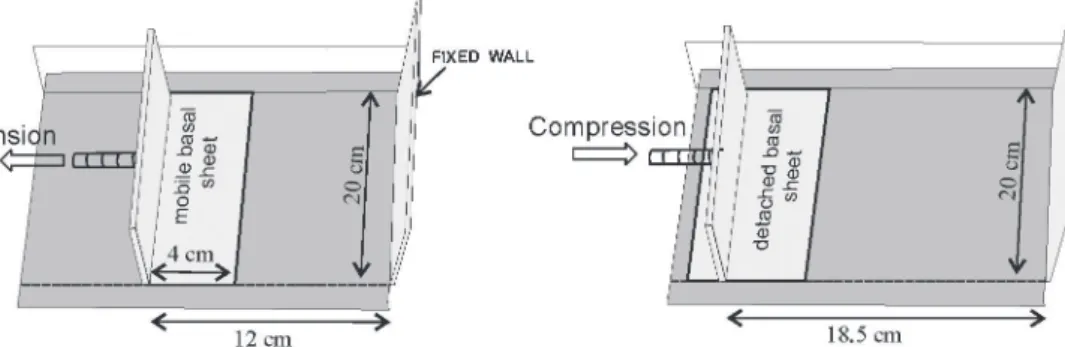
MODEL SET UP AND PROCEDURE
Six models were run under identical configurations
(Fig. 1), except for variations in two parameters. As mentioned above, we varied the basal detachment by changing the substrate, and we
modified the basin fill by using either the sand (in models called “sand basin fill experiments” or simply “sand models”) or the sand mica mixture
(14:1 ratio, by weight) used by Gomes (2013)
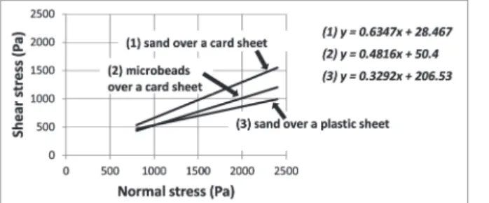
(in models called “sand mica mixture basin fill experiments” or simply “sand mica mixture models”). The first set of models (type I models)
was set up on a basal card sheet that had the highest
angle of sliding friction Φb = 32.37° (µb = 0.63).
card sheet was overlain by a 0.3-mm-thick layer
of highly spherical glass microbead, to produce an
intermediate value of sliding friction Φb = 25.68°
(µb = 0.48) during extension and shortening. In
the last set of models (type III models), analogue
materials were set up on a plastic sheet with the
lowest value of sliding friction for quartz sand Φb =
18.21° (µb = 0.33) (Fig. 2).
Figure 1 - Experimental apparatus.
All of the models had an initial length of 12 cm,
a width of 20 cm and a total thickness of 3 cm.
Each experiment involved two successive phases of deformation, both produced at a constant velocity of 0.69 x 10⁻³ cm/s (2.5 cm/h). During the first phase, a
rift was formed by a 6.5 cm (52 %) extension moving a basal sheet underlying part of the sand pack and fixed to the mobile wall (Fig. 1). It is important to note that in the type II models, the glass microbeads
overlaid the basal card sheet entirely only during the extensional phase. Due to the model set up, the microbeads were absent in the basin domain, so
that frictional constraints at the bases of the type II
models slightly changed during inversion.
At regular intervals (corresponding to 1 cm of
extension), the rift was filled with horizontal layers
of the sand mica mixture or sand, depending on the experiment, interlayered with thin, differently colored sand horizons. These sand horizons acted
as passive markers during extension and inversion.
For the sand mica mixture models, this procedure may have caused a small decrease in strain effect without changing the overall results. At the end
of the first phase of deformation, an additional 0.2 cm-thick layer of sand was sieved onto the
top of the model to simulate a post-rift sequence.
Before the onset of shortening, the basal sheet was detached from the mobile wall to avoid the formation of a velocity discontinuity. Lastly, the graben was subjected to a coaxial shortening of
3.5 cm (18.4 %).
To obtain a rheological difference for the pre- and syn-rift sequences in the sand models, the sand was deposited using different handling methods (following Krantz 1991). Thus, for the pre-rift sequence, the sand was sieved from a height of
20 cm, and for the basin fill, the sand was poured
from the basin shoulders (thus, the pouring height is considered to be 0 cm). According to Gomes (2013), sands sieved from a height of 20 cm and poured from 0 cm produce angles of internal
friction of Φi = 41.47° (µi = 0.88) and Φi = 37.63°
(µi = 0.77), respectively. To facilitate comparisons of the experimental results, the sand mica mixture was also poured from the basin shoulders. Pouring the sand mica mixture directly into the basin (height equals 0 cm) yields an angle of internal friction of
Φi = 36.02° (µi = 0.73) (Fig. 3). The bulk densities of the analyzed analog materials and their grain
sizes and shapes are listed in table I.
photographed. In addition, the amounts of extension
and shortening were recorded when the forward faults initiated. Because the results of progressive extension differed only slightly among our six
experiments, we show only the final extension of
6.5 cm, which represents a shortening of 0.0 cm in the sequential evolutionary stages of the inversion models (Fig. 4).
The main limitation of our experimental models relates to the lateral friction between the analog materials and the glass sides. Along these sidewalls, friction produces a higher local intergranular defor-mation, leading to slightly more plastic deformation. Another limitation of our model is that we describe only deformation produced along one sidewall: neither normal nor thrust fault distributions are
homogenous along strike.
To avoid misinterpretation, we present sections cut through the middle of the model
at final shortening and compare them with the
sidewall sections. This comparison shows that observations made along the glass sides agree well with the internal deformation observed in the middle sections.
SCALING
To ensure dynamic similarity between analogue models and nature, the modeling materials must have
angles of internal friction similar to those of rocks
(Hubbert 1937). According to Handin (1966), Byerlee
(1978) and Jaeger and Cook (1979), most rocks of the
upper crust have angles of internal friction between
31° and 41°. Therefore, both our sand mica mixture
and sand are suitable modeling materials.
Another condition for satisfying dynamic similarity, is to obey Hubbert’s (1937) scaling rela-tionship, σ*= ρ* x l* x g*, where σ*, ρ*, l* and g* correspond to the model-to-nature ratios for cohesion,
density, length and gravity, respectively. In sandbox experiments, g* is always 1, and ρ* does not signifi-cantly influence the equation results. Thus, l* defines σ*. If l* = 10-5, then 1 cm in the model corresponds
to 1 km in nature, and the cohesion of the sand and
the sand mica mixture must be < 100 Pa because
sedimentary rocks exhibit a cohesion that varies
between 10 MPa and 20 MPa (Handin 1966). The measured cohesion values of our analogue materials fall within the required range (according to Fig. 3, cohesion varies between 48.66 Pa and 122.73 Pa).
Figure 2 - Basal frictional properties of sand over card and
plastic sheets and glass microbeads over a card sheet at first peak strength (modified from Gomes 2013).
Figure 3 - Internal frictional properties of sand and sand mica mixture at first peak strength; h = height (modified from
Gomes 2013).
Analogue
material Composition Bulk density (kg/m3
)
Quartz sand
granulometry (µm) Mica granulometry (mm) Shape of quartz sand or mica
Sand
SiO2 = 99%, plus tourmaline, micas, opaque
1580 ≤ 350 -- subangular
Sand mica mixture
sand +
muscovite 940 ≤ 350 ≤ 1
subangular (sand) tabular (mica)
TABLE I
RESULTS
FIRST EXTENSIONAL DEFORMATION PHASE
The general geometric style of the extensional evolution is similar to those described in several previous studies that used a horizontal basal sheet to create a half graben (e.g., McClay and Ellis 1987, Panien et al. 2006, Eisenstadt and Sims 2005).
In all experiments, the extensional graben
was bounded by two opposite verging normal faults located at the edge of the basal sliding sheet. The graben-bounding fault dipping toward the mobile wall (right side, in Fig. 4) is called
“synthetic,” whereas the graben-bounding fault dipping toward the fixed wall (left side, in Fig. 4) is called “antithetic.” The antithetic border fault
formed in the part of the model that was passively transported over the basal sheet (for ease of description, this part of the model is called the
“left extensional block”).
Antithetic and synthetic border faults are always formed at the same time. During progressive deformation, a synthetic domino fault system deve-loped to accommodate extension in the basin to the left of the right-side border fault. Because of layer slip along the antithetic border fault during progressive extension, a relatively broad shear
zone formed, and the left side basin fill produced
an asymmetric syncline shape in the sand mica mixture models.
Differences between the different basin fill models
(the sand mica mixture and the sand models)
Comparisons of the extension in our six models show small differences in the number and nucleation
of normal faults and the deformation pattern. In all the sand mica mixture models, the final set of internal normal faults (F2 to F5) consisted of five
synthetic faults, and extension ended with the formation of a sixth antithetic fault in the upper part of the syn-rift sequence (Figs. 4(Ai), (Bi) and (Ci)). By contrast, the sand models were characterized
by six to seven synthetic faults, and no antithetic fault was formed (Figs. 4(Av), (Bv) and (Cv)).
In addition, the timing of normal fault nucleation
varied slightly more in the sand mica mixture models than in the sand models (Fig. 5).
Differences between the type I, II and III models related to the different detachments
With the exception of the type III models, both
border faults (both called F1 in Fig. 4) formed
after 0.5 cm of extension (Fig. 5). In the low-basal-friction type III models, the graben appeared only after 1.0 cm of extension. In the type I and II models, the synthetic border fault was always steeper (~ 80°) than the antithetic one (~ 60°). In the type III models, both border faults had approximately the same dip (~ 60°). Thus, the graben aperture measured at the top of basin fill was slightly higher in the type III models than in the type I and II models.
SECOND SHORTENING DEFORMATION PHASE
The cross-sectional structural evolutions of our six models are shown along the experimental box side walls after 1.5, 2.5 and 3.5 cm of mobile wall displacement in Fig. 4 and along sections cut through
the model centers at final shortening in Fig. 6. In our sand box experiments with different basin fills and detachments, inversion was accommodated by sand pack sliding along the basal
detachment and layer-parallel shortening followed by thrusting and upward movement of the thrust hanging wall. The normal faults in our six models
revealed insignificant reactivation that was only
recognized in a surface view (not shown), in which fault traces displayed minor differential uplifts. All of the models developed frontal
inversion-related folds, identified as fault-propagation folds,
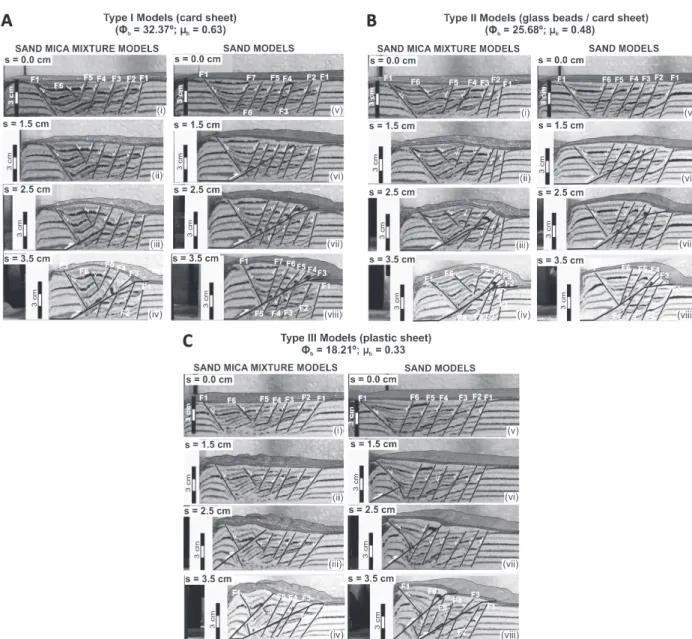
Figure 4 - Photographs of longitudinal side wall cross sections through sequential evolutionary stages of our type I (A), type II (B) and type III (C) inversion models. The first photograph in each model shows the final extension of 6.5 cm, corresponding to
0 cm of shortening (s = 0.0 cm) in the (second) deformation phase. Extension and shortening occurred on the left side. F1 to F7
are normal faults. Φb = angle of sliding friction; µb = coefficient of sliding friction.
Throughout the progressive inversion, normal faults were cut by the thrust and were passively carried
away. In the thrust hanging walls in the type I and II models, thrust fault displacement caused clockwise
rotation of the oldest normal faults (F2, F3 and F4) situated near the thrust tip (Fig. 4). The antithetic
border fault was also slightly rotated in a clockwise sense (2° to 3°). In the model center, this fault rotation
could also be observed but was more subtle (Fig. 6).
Differences between the type I, II and III models
related to the different basin fill (the sand mica
mixture and the sand models)
The most striking observation of our inversion
expe riments was the strong difference between the styles of internal deformation of the fault-propagation folds formed by the sand mica
in the extensional basin was accommodated by layer-parallel shortening (Fig. 7) and anticlinal ramp folding. The simple shear acting parallel to the fault surface during progressive displacement of the hanging wall produced apparently a drag along the thrust fault (Figs. 4Aiv, 4Biv and 4Civ). However, we relate the formation of the anticlinal ramp fold to passive folding in the sense used by Fossen (2010), who suggested that passive folding occurs ‘where the layering exerts no mechanical
influence on the folding’. Because our basin fill was set up without any significant competence-contrast
between layers, it seems reasonable that folding in our sand mica mixture experiments occurred
by passive grain flow. Due to the presence of
preexisting normal faults, folds are not homogenous from top to bottom.
Figure 5 - Normal faults plotted against extension measured at the moment a new fault nucleated: comparison among the different substrates (A) in the three sand mica mixture models and (B) in the three sand models (1 = card sheet, 2 = glass microbeads and card sheet and 3 = plastic sheet). Only the synthetic normal faults F1 to F7 are represented.
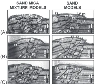
Figure 6 - Photographs of cross sections through the centers
of the models at final inversion. (A) type I models; (B) type
II models; (C) type III models; extension and shortening
occurred on the left sides.
Figure 7 - Line-drawings of the type I sand mica mixture experiment at initial
state (i.e. after extension) and after 3.5 cm of shortening to illustrate the layer-parallel shortening process, here shown by layers 1, 2, 3 and 4 near the antithetic border fault.
In the sand basin fill experiments, the
fault-propagation folds were formed by the uplift of the hanging walls and layer-parallel shortening; however, the layers stayed in their horizontal state (Figs. 4Aviii, 4Bviii and 4Cviii).
In the type III models, the low basal sliding
friction created two thrust faults in both sand and sand mica mixture models. The resulting deformation in the
A second remarkable difference between the
models using the sand mica mixture and the sand
is related to the timing of thrust nucleation. In the
three models using the sand mica mixture, thrusts formed after 2 cm of shortening, whereas in the sand models, the thrusts appeared earlier, after 1.0 cm (Figs. 4A(iii and vi), 4B(iii and vi) and 4C(iii and vi)). Here, two more aspects are noteworthy. First, despite their late nucleation, the thrust slip
measured during final shortening (measured by the
antithetic normal fault displacements) in the type
I and II sand mica mixture models, compares well
with that of the sand models (note that the thrust slip decreases towards the fault tip) (Fig. 8). Second, the magnitude of thrust slip measured during progressive deformation is always a little lower in the sand mica mixture than in the sand.
Differences between the type I, II and III models related to the different detachments
The different detachments caused a variation in the
internal deformation of the type I and II sand mica
mixture fault-propagation folds. The low sliding friction of the basal glass microbead layer in the type
II model caused a slightly higher thrust displacement than in the type I model (Fig. 8) as well as a minor
tightening of its thrust hanging wall during inversion (compare Figs. 4Ai to Aiv with 4Bi to Biv).
Consequently, in the sand mica mixture basin fill of the type II model, both layer-parallel shortening and folding were gentler than in the type I model.
Accordingly to Teixell and Koyi (2003), the highly spherical glass microbeads accommodate
layer-parallel shortening by bed thickening, whereas
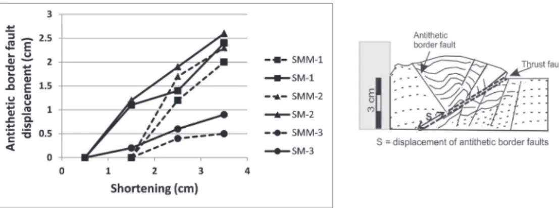
Figure 8 - Displacements of antithetic border faults along thrust faults plotted against shortening. Figure
to the right shows the insert of type I sand mica mixture model at final shortening, where thrust fault slip
was measured. SMM = sand mica mixture model; SM = sand model; 1 = card sheet; 2 = glass microbeads
and card sheet; 3 = plastic sheet. In type III models, only the first thrust was considered.
sand, composed of subangular grains, accommodate partly by volume reduction. Thus, the lower thrust
slip observed in both models of type I (sand mica
mixture and sand models) may also be related to the higher volume reduction of the sand at the experimental base.
The type III models differed considerably from the type I and II models. In the type III
models, set up on a plastic sheet at the base, a second thrust fault formed as mentioned above.
The first fault formed at the toe of the mobile wall (Fig. 4C), whilst, in the type I and II models,
the thrusts developed near the antithetic normal border fault (Figs. 4A and B).
As commonly observed in previous shortening analogue models (e.g., Mulugeta and Koyi 1987, Huiqi et al. 1992), the older thrust displayed a
DISCUSSION
THE EFFECT OF DIFFERENT BASIN FILL AND DIFFERENT BASAL DETACHMENT
Our experiments with different basin fills confirmed
the conclusions obtained by Gomes (2013) showing that although the sand and the sand mica mixture
possess a similar angle of internal friction (Φi =
37.63° and Φi = 36.02°, respectively), the latter shows a higher elasto-frictional plastic behavior
than sand. In the present study, we found two more reasons that confirm the higher elasto-frictional
plastic behavior of the sand mica mixture.
The first reason is related to the internal
deformation produced during inversion in the sand
mica mixture basin fill experiments. The
fault-propagation folds suggest that in the sand basins, the applied shortening (3.5 cm) was too small to
produce any grain flow other than layer-parallel
shortening. However, in the sand mica mixture
basins it was sufficient to produce folds by a distributed deformation that involved grain flow.
A comparison of our three sand mica
mixture basin fill experiments, set up on different
detachments, revealed that the degree of internal deformation in the analyzed mixture depends on the basal sliding friction (and not on a buttress effect). The higher the angle of basal friction, the higher was the internal plastic deformation, namely the
passive grain flow that led to the folds. We attribute the higher plastic deformation in the type I sand mica mixture basin fill, compared to the equivalent type II experiment, to a kinematic compensation
for its slightly lesser thrust displacement. Notably, the lowest angle of basal friction of our three sand mica mixture experiments favored faulting at the toe of the mobile wall and the development of a second thrust.
The second reason is related to faulting. In
the sand mica mixture experiments, the extension phase revealed a minor number of normal faults and slightly more irregular spacing of the normal
fault. During inversion, a delay in the thrust nucleation was observed in the sand mica mixture experiments in addition to the minor fault slip.
According to Panien et al. (2006), angular and subangular grain shapes and heterogeneous grain-size distributions produce a larger diffuse deformation because of the higher dispersion of stresses. The heterogeneous grain-shape distri bution of our sand mica mixture models, composed of subangular grains of quartz and tabular crystals of
mica, may be responsible for these kinematic features
in our experiments. Gomes (2013) described the stress-time curves of sand and sand mica mixtures obtained by ring-shear tests and revealed that sand has a stronger, more brittle behavior because it requires a lower amount of shear strain to reach failure than the sand mica mixture.
COMPARISON WITH PREVIOUS WORK
Although our models were performed with different boundary conditions, it is worth com-paring our results with those presented in analogue experiments by Panien et al. (2005). Among other features, those authors analyzed the effect of the
variation in basal friction on inversion. In their lowest-friction detachment experiment (ϕb = 12.5°), most of the deformation was transmitted to the graben and the thrust fault nucleated at the normal border fault. By contrast, in the higher-friction
experiment (ϕb = 28°), the thrust initiated close to the mobile wall.
Our models produced a different result, in that
the low basal friction in our type III model (ϕb =
18.21°) produced thrust fault initiation at the mobile backstop, and both the higher-basal-friction type I and II models produced thrusts near the graben
border fault.
In published pure contractional models, thrust
overlying a card sheet, in physical experiments developed by Gomes (2013). After 3 cm of contraction, these experiments revealed the formation of two thrusts, and in the sand model, both thrusts revealed a convex up geometry (Fig. 9). Because
only one thrust fault developed in our type I and II
inversion models and this fault maintained a straight geometry during progressive deformation, we suggest that the previous extensional basin interfered with thrusting. Thus, the experiments developed by Panien et al. (2005) may have produced a different result than ours due to the different distances between the mobile wall and the extensional basin, which were 10 cm and 4 cm, respectively.
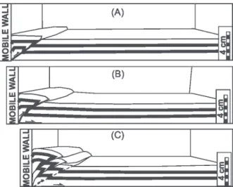
Figure 9 - Sequential line drawings of a shortening experiment, set up with sand overlying a card sheet (a) 1 cm contraction,
(b) 2 cm and (c) 4 cm (modified from Gomes 2013).
The evolution of our inversion models also contrasts with the experimental results presented
by Eisenstadt and Sims (2005). In their sand
models, shortening and coaxial inversion produced an almost identical thrust system, composed of a
forethrust and a backthrust bounding a passively
uplifted zone. However, in Eisenstadt and Sims (2005), the experimental set-up was completely different from ours. To produce the deformation, they did not use a mobile wall, but rather two
overlapping metal plates beneath their 4-cm-thick
layer of sand or clay, which caused a velocity discontinuity during inversion.
FINAL REMARKS
Tectonic inversion (horizontal plate movement) produces a variety of fault-related folds commonly formed by a buttress effect. Buttress folds are common structures in inversional fault hanging walls, related to the reactivation of normal faults, and have been simulated in several physical models (e.g., Buchanam and McClay 1991, McClay 1995).
In our models, reactivation of normal faults was insignificant, and new reverse faults juxtaposed
analog materials of the same rheology. The entire
system was compressed between blocks of higher
or equally brittle strength (the sand mica mixture and the sand experiments, respectively), and the fault-propagation folds resulted from the internal
deformation of each basin fill analogue material,
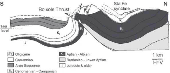
varying with different basal sliding friction values. The fault-propagation folds simulated in our analogue experiments may be compared to the Sant Corneli-Boixols-Nargo anticline at the leading edge of the Boixols thrust sheet, described by Bond and McClay (1995) in the Lower Cretaceous extensional basin, south-central Pyrenees Mountains of Spain (Fig. 10). Those authors found broad similarities between the geometry of the Sant Corneli-Boixols-Nargo anticline and that of the inverted extensional half-graben models developed by Buchanam and McClay (1991). Because Buchanam and McClay’s (1991) experiments had been set up with a rigid
footwall block that acted as a buttress and the sand
was interlayered with thin mica layers, folding in their experiments was a consequence of
layer-parallel slip. Therefore, their folds are flexural-slip
We suggest using the sand mica mixture for
simulating basin fills in mild inversion tectonics, in
geological settings characterized by sequences of
low mechanical contrast between layers. In these
models the internal deformation might be increased using a high-basal-friction detachment.
ACKNOWLEDGMENTS
We want to express our gratitude to Petróleo Brasileiro S/A (Petrobrás) for improvement of our Tectonic Modeling Laboratory (T.C. 0050.0044772.08.04) and Fundação de Amparo à
Pesquisa do Estado de Minas Gerais (FAPEMIG) (CRA-APQ-01672-11) for financial support. We would also like to thank two anonymous reviewers
for constructive suggestions to improve the
manuscript. Lastly, thanks go out to Universidade Federal de Ouro Preto for additional financial
support for language editing.
RESUMO
Compara-se a deformação produzida em areia e em uma mistura de areia com cristais de micas (na proporção 14:1, em peso), empregadas para simular o preenchimento de uma bacia em modelos de extensão e inversão, para analisar o potencial da mistura areia com cristais de micas para o uso em modelos físicos que requerem um material analógico,
de fortes propriedades elasto-fricional plásticas. A areia e a mistura areia com cristais de micas possuem ângulos de atrito interno, similares, mas a mistura se deforma sob
uma tensão cisalhante crítica significativamente mais
baixa. Na extensão, os experimentos nos quais a mistura areia com cristais de micas preenche as bacias revelam um número menor de falhas normais. Durante a inversão, a diferença mais importante entre as bacias, preenchidas com areia e com a mistura areia com cristais de micas, é relacionada à deformação interna de dobras de propagação de falhas que cresce com o aumento do ângulo de atrito basal. Conclui-se que a mistura areia com cristais de micas, de fortes propriedades elasto-fricional plásticas, pode ser empregada para a simulação de dobras em experimentos que pretendem simular uma inversão moderada, na crosta rúptil.
Palavras-chave: modelagem analógica, mistura areia e cristais de micas, inversão tectônica, atrito basal, dobras de propagação de falhas.
REFERENCES
BAHROUDI A, KOYI HA AND TALBOT CJ. 2003. Effect of ductile and frictional décollements on style of extension. J Struct Geol 25: 1401-1423.
BOND RMG AND MCCLAY KR. 1995. Inversion of a Lower Cretaceous extensional basin, south central Pyrenees,
Spain. In: BUCHANAN JG AND BUCHANAN PG (Eds), Basin Inversion. Geol Soc London Spec Publ 88:
415-432.
Figure 10 - The Sant Corneli-Boixols-Nargo anticline at the Boixols thrust sheet in the Lower Cretaceous
BUCHANAN PG AND MCCLAY KR. 1991. Sandbox experiments of inverted listric and planar fault systems. Tectonophys 188: 97-115.
BYERLEE J. 1978. Friction of rocks. Pure Appl Geophys 116: 615-626.
EISENSTADT G AND SIMS D. 2005. Evaluating sand and clay models: do rheological differences matter? J Struct Geol 27: 1399-1412.
FOSSEN H. 2010. Structural Geology. Cambridge University
Press, New York, 584 p.
GOMES CJS. 2013. Investigating new materials in the context of analog-physical models. J Struct Geol 46: 158-166. HANDIN J. 1966. Strength and ductility. In: CLARK SP Jr.
(Ed), Handbook of Physical Constants. Geol Soc Am,
Memoir 97: 223-289.
HUBBERT MK. 1937. Theory of scale models as applied to the study of geologic structures. Geol Soc Am Bull 48: 1459-1520.
HUIQI L, MCCLAY KR AND POWELL D. 1992. Physical models
of thrust wedges. In: McCLAY KR (Ed), Thrust Tectonics,
Chapman & Hall; London, p. 71-81.
JAEGER JC AND COOK NGW. 1979. Fundamentals of Rock
Mechanics. Chapman and Hall, Wiley, New York, 513 p.
KRANTZ RW. 1991. Measurements of friction coefficients and cohesion for faulting and fault reactivation in laboratory models using sand and sand mixtures. Tectonophys 188: 203-207.
LOHRMANN J, KUKOWSKI N, ADAM J AND ONCKEN O. 2003. The impact of analogue material properties on the
geometry, kinematics and dynamics of convergent sand
wedges. J Struct Geol 25: 1691-1711.
MANDL G. 1988. Mechanics of Tectonic Faulting. Models and Basic Concepts. Elsevier, Amsterdam, 407 p.
MASSOLI D, KOYI HA AND BARCHI MR. 2006. Structural evolution of a fold and thrust belt generated by multiple décollements: analogue models and natural examples
from the Northern Apennines (Italy). J Struct Geol 28:
185-199.
MCCLAY KR. 1990. Extensional fault systems in sedimentary basins: a review of analogue model studies. Marine and Petrol Geol 7: 206-233.
MCCLAY KR. 1995. The geometries and kinematics of
inverted systems: a review of analogue model studies. In:
BUCHANAN JG AND BUCHANAN PG (Eds), Basin
Inversion. Geol Soc Special Pub 88: 97-118.
MCCLAY KR AND ELLIS PG. 1987. Geometries of extensional fault systems developed in model experiments. Geology 15: 341-344.
MULUGETA G AND KOYI HA. 1987. Three-dimensional geometry
and kinematics of experimental piggyback thrusting.
Geology 15: 1052-1056.
PANIEN M, SCHREURS G AND PFIFFNER A. 2005. Sandbox
experiments on basin inversion: testing the influence of basin orientation and basin fill. J Struct Geol 27: 433-445.
PANIEN M, SCHREURS G AND PFIFFNER A. 2006. Mechanical behavior of granular materials used in analogue modeling: insights from grain characterization, ring-shear tests and analogue experiments. J Struct Geol 28: 1710-1724. RUTTER EH. 1986. On the nomenclature of mode of failure
transition in rocks. Tectonophys 122: 381-387.
SCHELLART WP. 2000. Shear test results for cohesion and
friction coefficients for different granular materials:
scaling implications for their usage in analogue modeling. Tectonophys 324: 1-16.
SCHREURS G ET AL. 2006. Analogue benchmarks of shortening
and extension experiments. In: BUITER SJH AND
SCHREURS G (Eds), Analogue and Numerical Modelling of Crustal-Scale Processes. Geol Soc Lond Spec Publ 253: 1-27.
SOTO R, MARTINOD J AND ODONNE F. 2007. Influence of
early strike-slip deformation on subsequent perpendicular
shortening: An experimental approach. J Struct Geol 29: 59-72.
STORTI F AND MCCLAY K. 1995. Influence of syntectonic sedimentation on thrust wedges in analogue models. Geology 23: 999-1002.
TEIXELL A AND KOYI HA. 2003. Experimental and field study of the effects of lithological contrasts on thrust-related deformation. Tectonics 22: 1054-1073.
VENTISETTE C, MONTANARI D, SANI F AND BONINI M. 2006. Basin inversion and fault reactivation in laboratory experiments. J Struct Geol 28: 2067-2083.